Electronics Production
This week was about Electronics Production, the purpose is to create our circuit on a PCB board where the XIAO-RP2040 microcontroller will be. As a final objective, we will have a printed circuit on a copper plate that can make 2 LEDs blink and when the button is pressed, the third LED will begin to blink.
As a first step we cut the copper plate and glue it on a sacrificial bed, which in this case is made of MDF, this is useful in case the perforation exceeds the copper plate. Once the copper plate is glued to the "sacrifice bed" we proceed to screw it in the mini mill machine
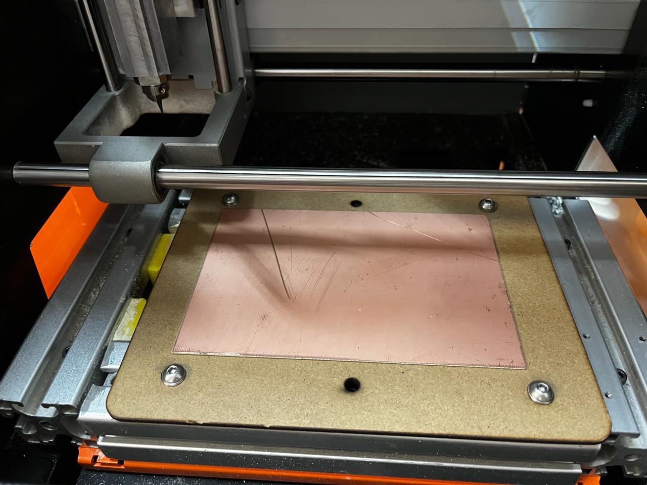
As a first step we cut the copper plate and glue it on a sacrificial bed, which in this case is made of MDF, this is useful in case the perforation exceeds the copper plate. Once the copper plate is glued to the "sacrifice bed" we proceed to screw it in the mini mill machine
Mini Mill Model
ROLAND SRM-20

- Cutable Material: Modeling Wax, Chemical Wood, Foam, Acrylic, Polyacetal, Acrylonitrile Butadiene Styrene (ABS), Printed Circuit Boards
- Operational Travels in X, Y, and Z: 203.2 mm (X) × 152.4 mm (Y) × 60.5 mm (Z)r
- Loadable Workpiece Weight: 2 kg
- Operation Speed: From 6 mm/min to 1,800 mm/min
- Software Resolution: 0.01 mm/step (RML-1), 0.001 mm/step (NC Code)
- Mechanical Resolution: 0.000998594 mm/step
- Spindle Rotation Speed: Adjustable from 3,000 RPM to 7,000 RPM
- Interface: USB
- Operational Noise: During operation: 65 dB(A)
- External Dimensions: 451 mm (width) × 426.6 mm (depth) × 426.2 mm (height) (17.76 in [width] × 16.80 in [depth] × 16.78 in [height])
- Weight: 19.6 kg
Traces
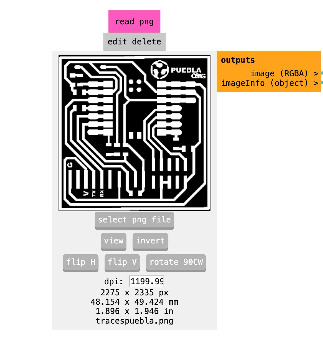
The design seen below is a png image so the machine cannot read it, so we will convert it to G-code using the platform https://modsproject.org/ then selecting the corresponding program on our machine, it will show a route like this

Traces Image png

We upload the Traces
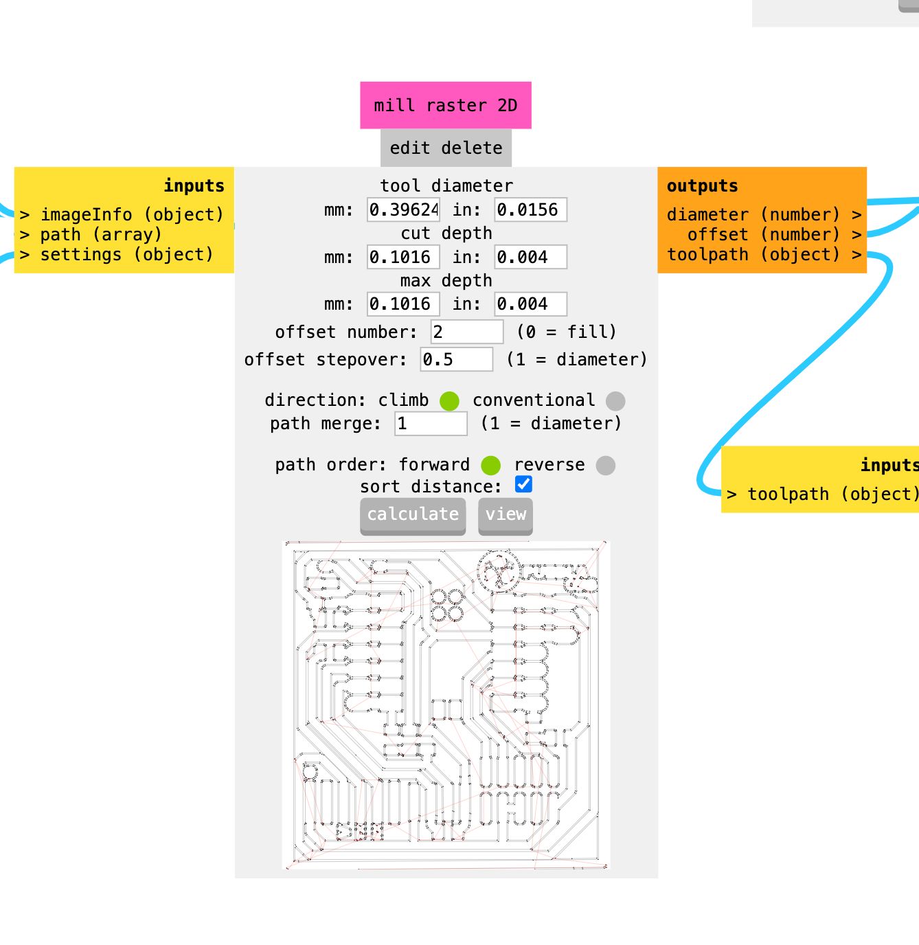
Once the image is loaded, it automatically chooses the mill raster parameters, changing the offset to 2
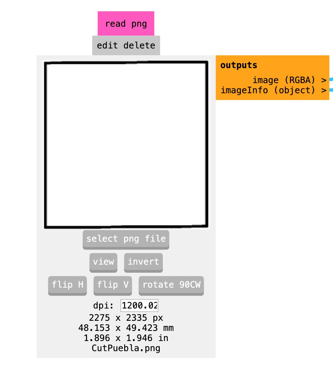
Cut
We do the samething we upload the cut png file but in this case we need to invert the image
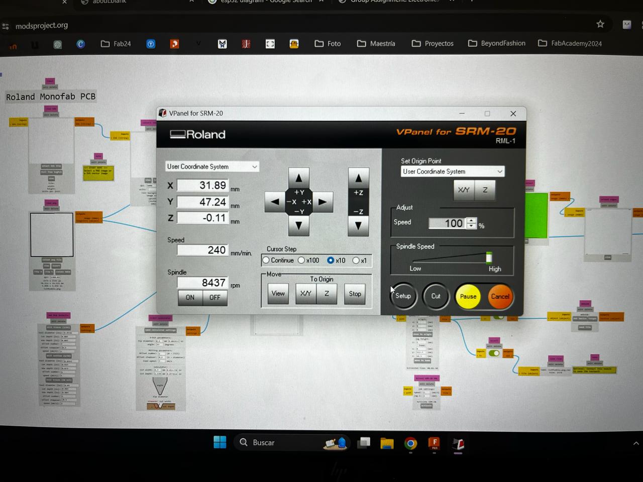
VPanel for the ROLAND SRM-20
This program help us to configurate the axies for the milling, we set up the origin at the bottom left
Nice! Once we set up the machine we need to use two tools.
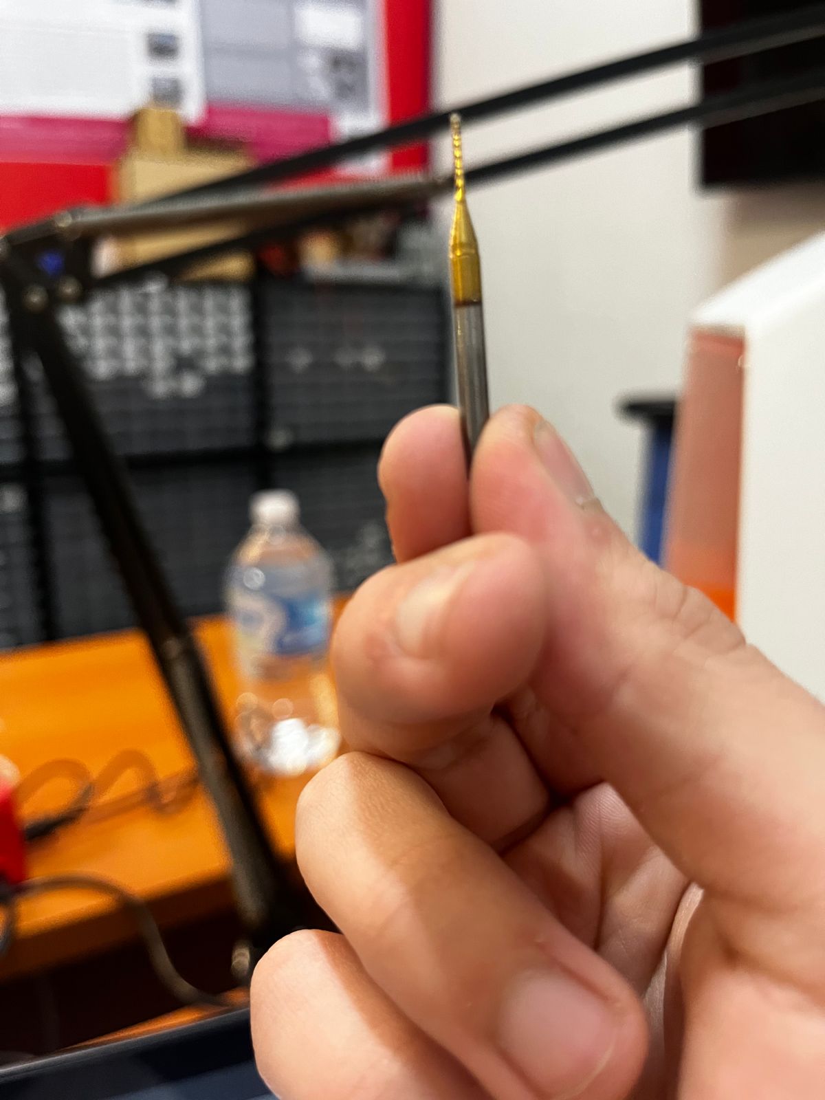
For engraving we're using a 15 degree V-bit
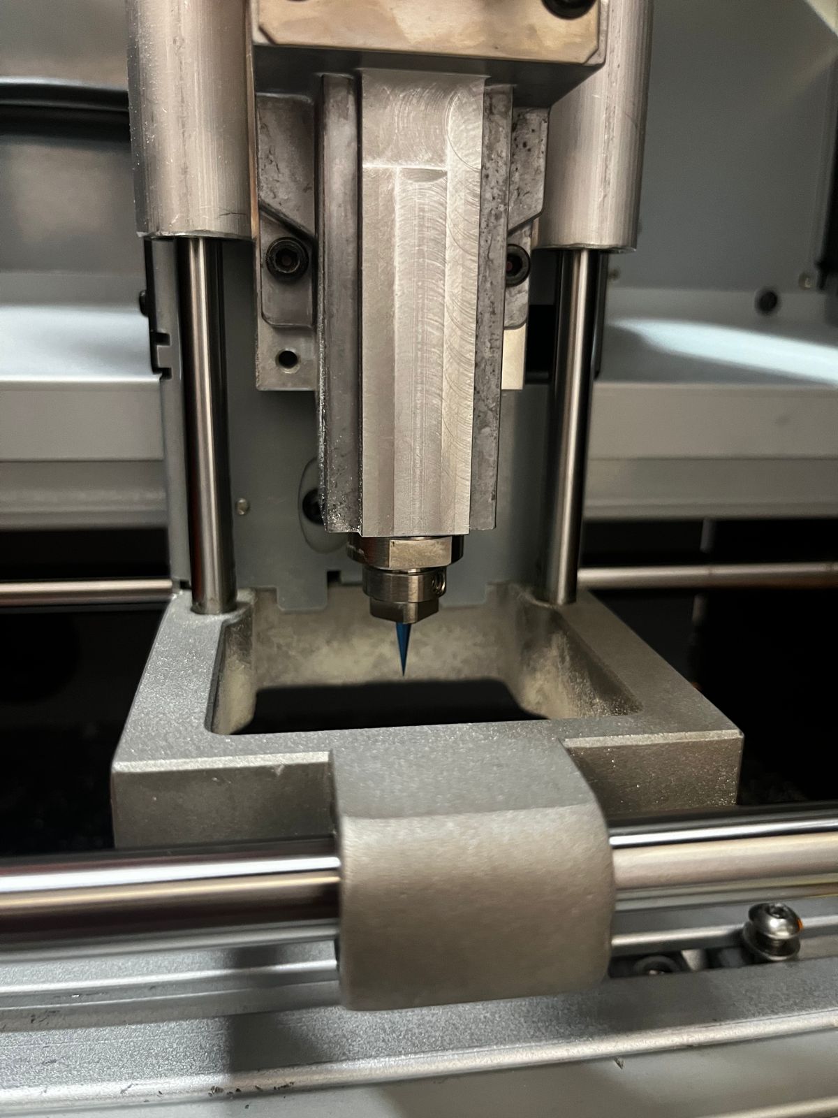
And for cutting we're using a 0.8 mm diameter two flute end Mill.
Once we press Cut in the VPanel it is going to start cutting the PCB
¡LET'S CUTT!
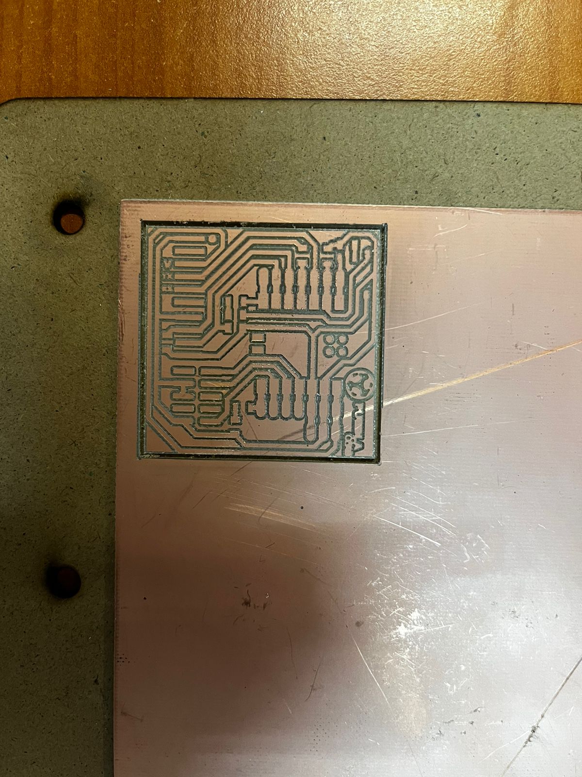
The cutting process took approximately 18 minutes resulting in this wonderful PCB board.
Solding time
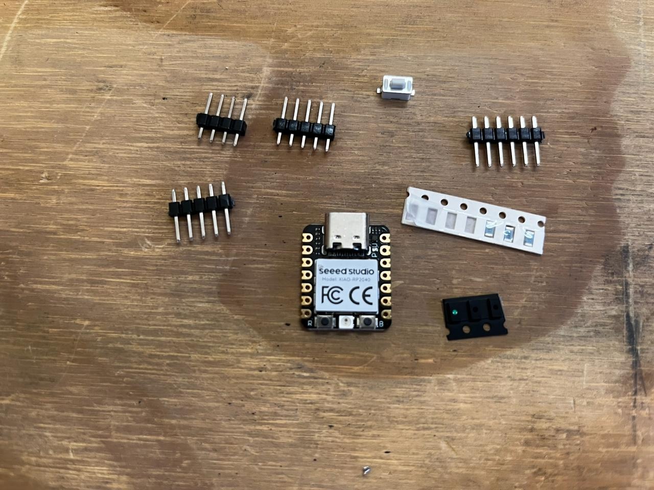
Materials
- 1 XIA0-RP2040
- 6 resistances of 1.5KΩ
- 3 superficial LEDs
- 1 button
- 1 row of pins
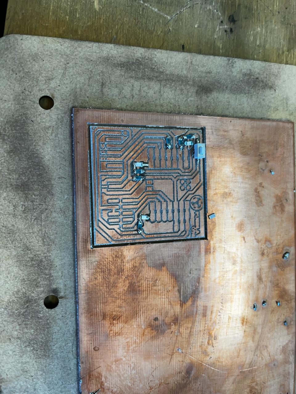
I started to solder the smaller components which are the resistors, the LEDs and the button, so that when soldering the other components they do not interfere with each other.
We proceed to solder the big components, which is the microcontroller and the pins each one in their respective places.
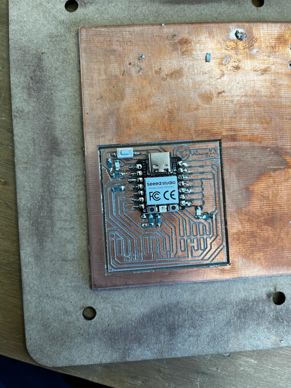
result of the PCB already with all the components soldered

ARDUINO PROGRAM
ARDUINO IDE was used to make the code, and this code consists of when you connect the PCB. Two LEDs turn on and start blinking, but when the button is pressed, the third LED turns on and starts blinking.

Final result
The final result was satisfactory, when we press the button, the third LED start blinking