6. Embedded Programming
For this week's practice we were asked to write a program for a development board with a
microcontroller. This must have exits and entrances. In addition to being able to communicate. And
as an extra, use different languages and development environments.
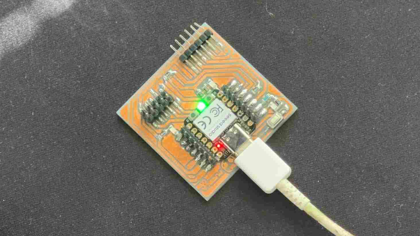
To carry out this practice, I used Arduino and Python, in addition to which I designed and
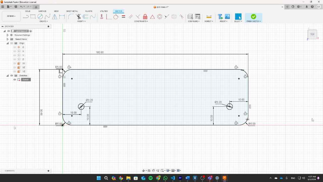
manufactured a PCB to connect to the board that we manufactured in week four
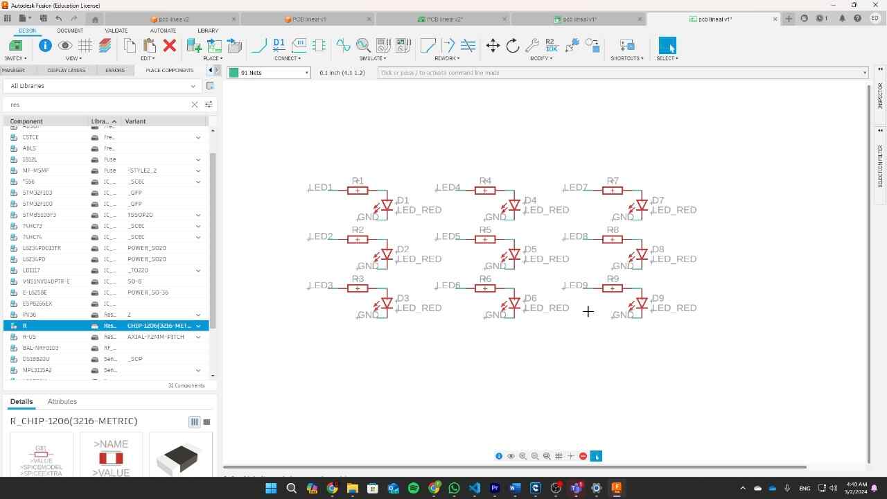
The idea for this project was to create a pin-pong type game with several LEDs in a row, this would
have nine LEDs and two buttons. I started with the design of the PCB, and once I had the plan, I
began the task of making the program. I first started with Arduino since I have used it in the past
and having the code ready I just passed it to the Python syntax
Arduino (C++)
Arduino is an open source platform used for creating electronics projects. The Arduino
development environment is an easy-to-use software that allows you to write, compile, and
upload code to the board's microcontroller. This software is compatible with operating
systems such as Windows, macOS and Linux. Programming is done in a language similar to
C/C++, which makes it easy to learn and use, especially for those who already have
experience in these languages.
Circuit Python
Python is a general-purpose, interpreted, high-level programming language designed with a
focus on code readability. It is a multi-paradigm programming language, which means that it
supports different programming styles, such as object-oriented, imperative, functional and
procedural programming. This makes it extremely flexible and suitable for a wide range of
applications. Python runs on a variety of platforms, including Windows, macOS, Linux, and
has been ported to Java and .NET in virtual environments.
Syntax comparison
|
ARDUINO (C++) |
PHYTHON |
| Control Structures |
Opening and closing of keys |
Tab hierarchy |
| Variables |
Variable type specification int, float, char, etc |
automatically determines the type of variable |
| Comments |
//comment and */more comments/ * |
#comment and '''more commnets''' |
| Functions |
Specify the return |
Using def with arguments |
| Delay |
(import time) time.sleep(1) one second |
Delay(1000) one second |
| Input |
#define push 25
pinMode(push, INPUT) |
x = digitalio.DigitalInOut(board.GP25)
push.direction =
digitalio.Direction.INPUT |
| Output |
#define led 25
pinMode(led, OUTPUT) |
x = digitalio.DigitalInOut(board.GP25)
led.direction =
digitalio.Direction.OUTPUT |
| Write |
digitalWrite(led,HIGH)
digitalWrite(led,LOW) |
led.value = True
led.value = False |
| Read |
digitalRead(push) |
push_value = push.value |
| Printing |
Serial.prinln("hello, wold") |
print("hello, wold") |
for more information visit the GROUP PAGE
Programming
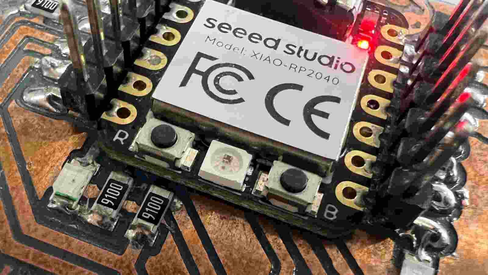
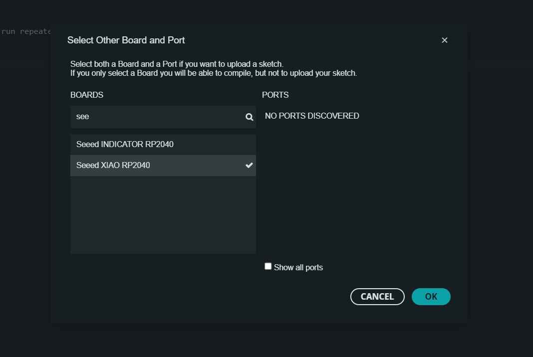
To start programming our microcontroller, we first need to prepare our microcontroller for the
programming language we are going to use. To do this on my SEED XIAO rp2040 microcontroller, you
will press the B button on the board and, while keeping it pressed, connect it to the computer. This
folder will not appear on the computer. This active the mode bootloader
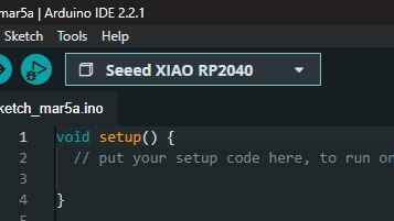
for Arduino
In this mode, we will open the Arduino program and look for the following option
We will look for the seeed xiao rp2040 board and we will give ok
Now the board recognizes us and we can load the code from the Arduino program.
arduino
for Python
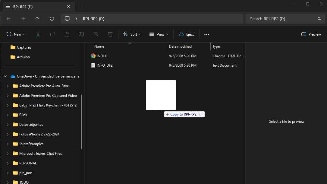
Inside the board folder, we will drag the bootloader for python, and we wait for the folder
to open again
The folder should look like this
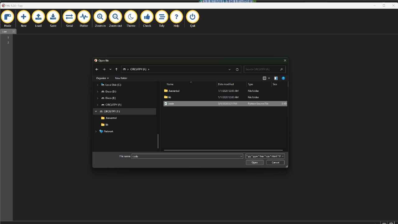
In mu Editor we will load the code file and that's it, we can load code if you press the save
button
mu Editor
Having the program ready and the Bootloader installed on the micro controller. Just upload the code
for it to work, the following are the programs I created in Arduino and Python that do exactly the
same thing

ARDUINO
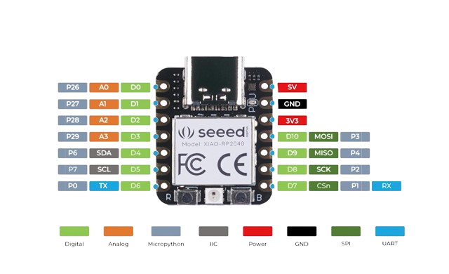
In this part of the code, I assign a name to each port of the microcontroller, following the given image.
									//DEFINE PINS-------------------------


										#define push1 D0

										#define push2 D1


										#define led1 D2

										#define led2 D3

										#define led3 D4

										#define led4 D5

										#define led5 D6

										#define led6 D7

										#define led7 D8

										#define led8 D9

										#define led9 D10
ARDUINO
Flags will allow the button to detect only one press when it is pushed. The other variables are counters that let us see the state of the game; the 'state' variable indicates whether the main counter starts to increase or decrease.
										//VARIABLES-----------------------------------


										int flag1 = 1;        //flag for the buttons

										int flag2 = 1;


										int cont = 0;         //main counter to turn on leds

										int cont_vel = 0;     //counter to determine speed

										int state = 1;        //counter increases(1) or decreases(0)

										int game = 0;         //start game

										int cont_red=0;       //count when you reach the color red
ARDUINO
void setup() is the main configuration of the program. In this, we establish communication and the modes of the pins.
Serial.begin is the speed at which we will communicate with the monitor that Arduino includes, a tool that facilitates communication.
pinMode determines if the pin is an input or output; for buttons, they will be inputs, and for LEDs, they will be outputs.
										void setup() {


											Serial.begin(9600);          //comunication

											//PINMODE-------------------------------------------

											  pinMode(push1,INPUT);        //buttons

											  pinMode(push2,INPUT);


											  pinMode(led1,OUTPUT);        //LEDS

											  pinMode(led2,OUTPUT);

											  pinMode(led3,OUTPUT);

											  pinMode(led4,OUTPUT);

											  pinMode(led5,OUTPUT);

											  pinMode(led6,OUTPUT);

											  pinMode(led7,OUTPUT);

											  pinMode(led8,OUTPUT);

											  pinMode(led9,OUTPUT);

										  }
ARDUINO
Here, we create a start for the game. It is necessary to press both buttons for the game to start. It will send a "Start" message. Then it will perform a sequence of turning all the LEDs on and off.
										void loop()

											//START GAME----------------------------------------

											  //press the two buttons to start, small blink and

											  //I enter the game loop

											  if ((digitalRead(push1)==1) && (digitalRead(push2)==1)) {

												game=1;

												Serial.println("--------START----------");

												(digitalWrite(led1,1));

												(digitalWrite(led2,1));

												(digitalWrite(led3,1));

												(digitalWrite(led4,1));

												(digitalWrite(led5,1));

												(digitalWrite(led6,1));

												(digitalWrite(led7,1));

												(digitalWrite(led8,1));

												(digitalWrite(led9,1));

												delay(50);

												(digitalWrite(led1,0));

												(digitalWrite(led2,0));

												(digitalWrite(led3,0));

												(digitalWrite(led4,0));

												(digitalWrite(led5,0));

												(digitalWrite(led6,0));

												(digitalWrite(led7,0));

												(digitalWrite(led8,0));

												(digitalWrite(led9,0));

												delay(50);

												state=1;

											  }
ARDUINO
By pressing both buttons, the 'Game' variable will change to one, and we will enter the game cycle. 'Game Speed' will start at 100, and each time it repeats, it decreases by one. In this way, the internal delay will repeat fewer times, making the game faster.
Here, flags are applied so that the code repeats only once and nothing happens if we keep the first button pressed so that the main counter increases, and the second button will cause it to decrease.
										//GAME LOOP-----------------------------------------

											while(game==1)

											//game speed

											for (int x=100; x>=cont_vel; x--) {

											delay(2);

											}

											//first button with flag, counter increases and

											//speed increases

											if ((digitalRead(push1)==1) && (flag1==1)) {

											state=1;

											cont_vel++;

											flag1=0;

											}

											if((digitalRead(push1)==0) && (flag1==0)){

											flag1=1;

											}

											//second button with flag, counter decreases

											//and speed increases

											if ((digitalRead(push2)==1) && (flag2==1)) {

											state=0;

											flag2=0;

											cont_vel++;

											}

											if((digitalRead(push2)==0) && (flag2==0)){

											flag2=1;

											}
ARDUINO
Our main counter has 10 different cases: zero and ten are the limits where if we enter them, we would lose the game. Cases zero and ten will make the LEDs blink, indicating that you lost, and cases one to nine turn on the LEDs independently.
										switch (cont) {

											//blink and we give up the game

											case 0:

											  for (int x=0; x<=5; x++) {

												(digitalWrite(led1,1));

												(digitalWrite(led2,1));

												(digitalWrite(led3,1));

												(digitalWrite(led4,1));

												(digitalWrite(led5,1));

												(digitalWrite(led6,1));

												(digitalWrite(led7,1));

												(digitalWrite(led8,1));

												(digitalWrite(led9,1));

												delay(100);

												(digitalWrite(led1,0));

												(digitalWrite(led2,0));

												(digitalWrite(led3,0));

												(digitalWrite(led4,0));

												(digitalWrite(led5,0));

												(digitalWrite(led6,0));

												(digitalWrite(led7,0));

												(digitalWrite(led8,0));

												(digitalWrite(led9,0));

												delay(100);

											  }

												game=2;

											break;
										case 1:

										(digitalWrite(led1,1));

										(digitalWrite(led2,0));

										(digitalWrite(led3,0));

										(digitalWrite(led4,0));

										(digitalWrite(led5,0));

										(digitalWrite(led6,0));

										(digitalWrite(led7,0));

										(digitalWrite(led8,0));

										(digitalWrite(led9,0));

										cont_red++;

										Serial.println("red");

									  break;


									  case 2:

										(digitalWrite(led1,0));

										(digitalWrite(led2,1));

										(digitalWrite(led3,0));

										(digitalWrite(led4,0));

										(digitalWrite(led5,0));

										(digitalWrite(led6,0));

										(digitalWrite(led7,0));

										(digitalWrite(led8,0));

										(digitalWrite(led9,0));

									  break;

PYTHON
In this part, I defined the input and output pins of the ports on the board. In the case of the buttons, we also have to declare the type of button. We declare the pins, as seen in the image.
										#DEFINE PINS-------------------------


										push1 = digitalio.DigitalInOut(board.D0)

										push1.direction = digitalio.Direction.INPUT

										push1.pull = digitalio.Pull.DOWN

										push2 = digitalio.DigitalInOut(board.D1)

										push2.direction = digitalio.Direction.INPUT

										push2.pull = digitalio.Pull.DOWN


										led1 = digitalio.DigitalInOut(board.D2)

										led1.direction = digitalio.Direction.OUTPUT

										led2 = digitalio.DigitalInOut(board.D3)

										led2.direction = digitalio.Direction.OUTPUT

										led3 = digitalio.DigitalInOut(board.D4)

										led3.direction = digitalio.Direction.OUTPUT

										led4 = digitalio.DigitalInOut(board.D5)

										led4.direction = digitalio.Direction.OUTPUT

										led5 = digitalio.DigitalInOut(board.D6)

										led5.direction = digitalio.Direction.OUTPUT
PYTHON
In the case of this code, I had to import some libraries: import boar` and import digitalio. These will help us assign the pins and determine if they are inputs or outputs. Import time will allow us to pause the code for a specified amount of time using time.sleep().
Flags will allow the button to detect only one press when it is pushed. The other variables are counters that let us see the state of the game; the state variable indicates whether the main counter starts to increase or decrease.
										#IMPORT LIBRARIES--------------------

										import board

										import digitalio

										import time


										#VARIABLES--------------------------------

										flag1 = 1       #flag for the buttons

										flag2 = 1


										cont = 0        #main counter to turn on leds

										cont_vel = 1    #counter to determine speed

										state = 1       #counter increases(1) or decreases(0)

										game = 0        #start game

										cont_red = 0    #count when you reach the color red
PYTHON
Here, we create a start for the game. It is necessary to press both buttons for the game to start. It will send a "Start" message. Then it will perform a sequence of turning all the LEDs on and off.
										while True:

										#START GAME----------------------------------------

										  #press the two buttons to start, small blink and I enter the game loop

										  if push1.value == True and push2.value == True :

											  game = 1

											  print("-----------START-------------")

											  led1.value = True

											  led2.value = True

											  led3.value = True

											  led4.value = True

											  led5.value = True

											  led6.value = True

											  led7.value = True

											  led8.value = True

											  led9.value = True

											  time.sleep(.05)

											  led1.value = False

											  led2.value = False

											  led3.value = False

											  led4.value = False

											  led5.value = False

											  led6.value = False

											  led7.value = False

											  led8.value = False

											  led9.value = False

											  time.sleep(.05)

											  state=1
PYTHON
By pressing both buttons, the 'Game' variable will change to one, and we will enter the game cycle. 'Game Speed' will start at 100, and each time it repeats, it decreases by one. In this way, the internal delay will repeat fewer times, making the game faster
Here, flags are applied so that the code repeats only once and nothing happens if we keep the first button pressed so that the main counter increases, and the second button will cause it to decrease.
										#GAME LOOP---------------------------------

										while game == 1:


											#game speed

											for x in range(0,100-cont_vel):

												time.sleep(0.001)


											#first button with flag, counter increases

											and speed increases

											if push1.value == True and flag1 == True:

												state = 1

												cont_vel = cont_vel + 1

												flag1 = 0

											if push1.value == False and flag1 == False:

												flag1 = 1


											#second button with flag, counter decreases

											#and speed increases

											if push2.value == True and flag2 == True:

												state = 0

												cont_vel = cont_vel + 1

												flag2 = 0

											if push2.value == False and flag2 == False:

												flag2 = 1


											#counter increases or decreases

											if state == 1:

												cont = cont + 1

											if state == 0:

												cont = cont - 1
PYTHON
For Python, there is no `case` statement, so I had to write the code using the `if` statement, which essentially serves the same purpose.
										#cases for the accountant

										if cont == 0:

											#blink and we give up the game

											for x in range(0,6):

												led1.value = True

												led2.value = True

												led3.value = True

												led4.value = True

												led5.value = True

												led6.value = True

												led7.value = True

												led8.value = True

												led9.value = True

												time.sleep(.05)

												led1.value = False

												led2.value = False

												led3.value = False

												led4.value = False

												led5.value = False

												led6.value = False

												led7.value = False

												led8.value = False

												led9.value = False

												time.sleep(.05)

											game = 2
										#LED1 turns on and network increases

										if cont == 1:

											led1.value = True

											led2.value = False

											led3.value = False

											led4.value = False

											led5.value = False

											led6.value = False

											led7.value = False

											led8.value = False

											led9.value = False

											cont_red = cont_red + 1


										#LED2 turns on and network increases

										if cont == 2:

											led1.value = False

											led2.value = True

											led3.value = False

											led4.value = False

											led5.value = False

											led6.value = False

											led7.value = False

											led8.value = False

											led9.value = False
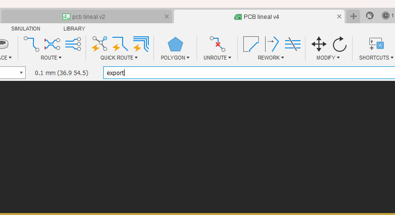
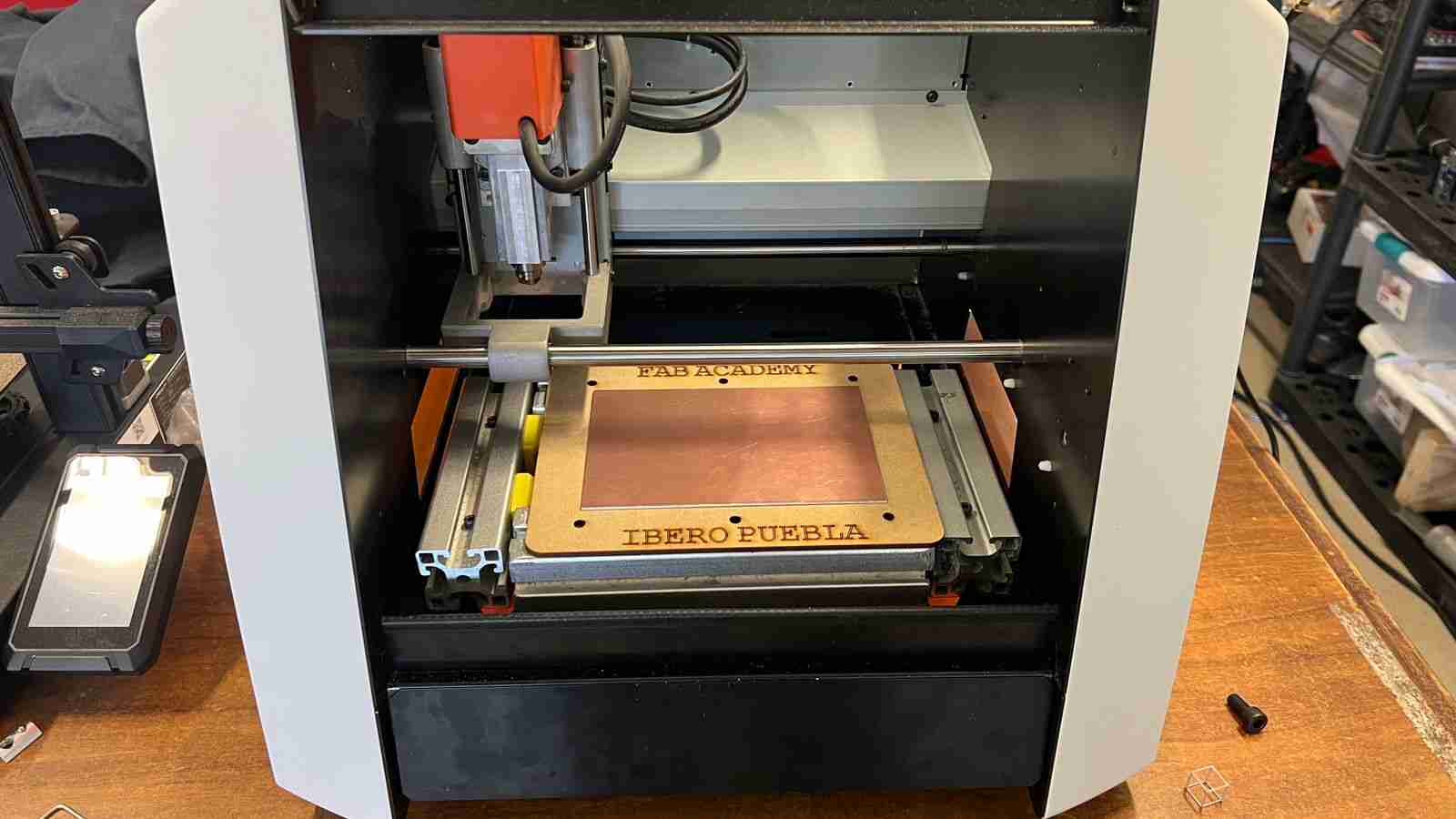
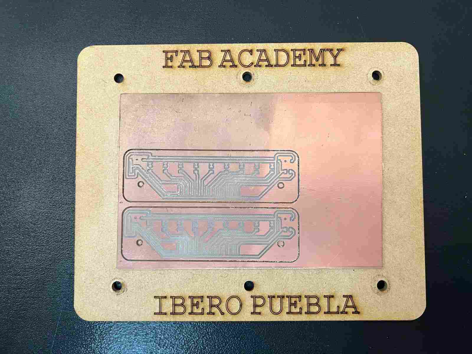
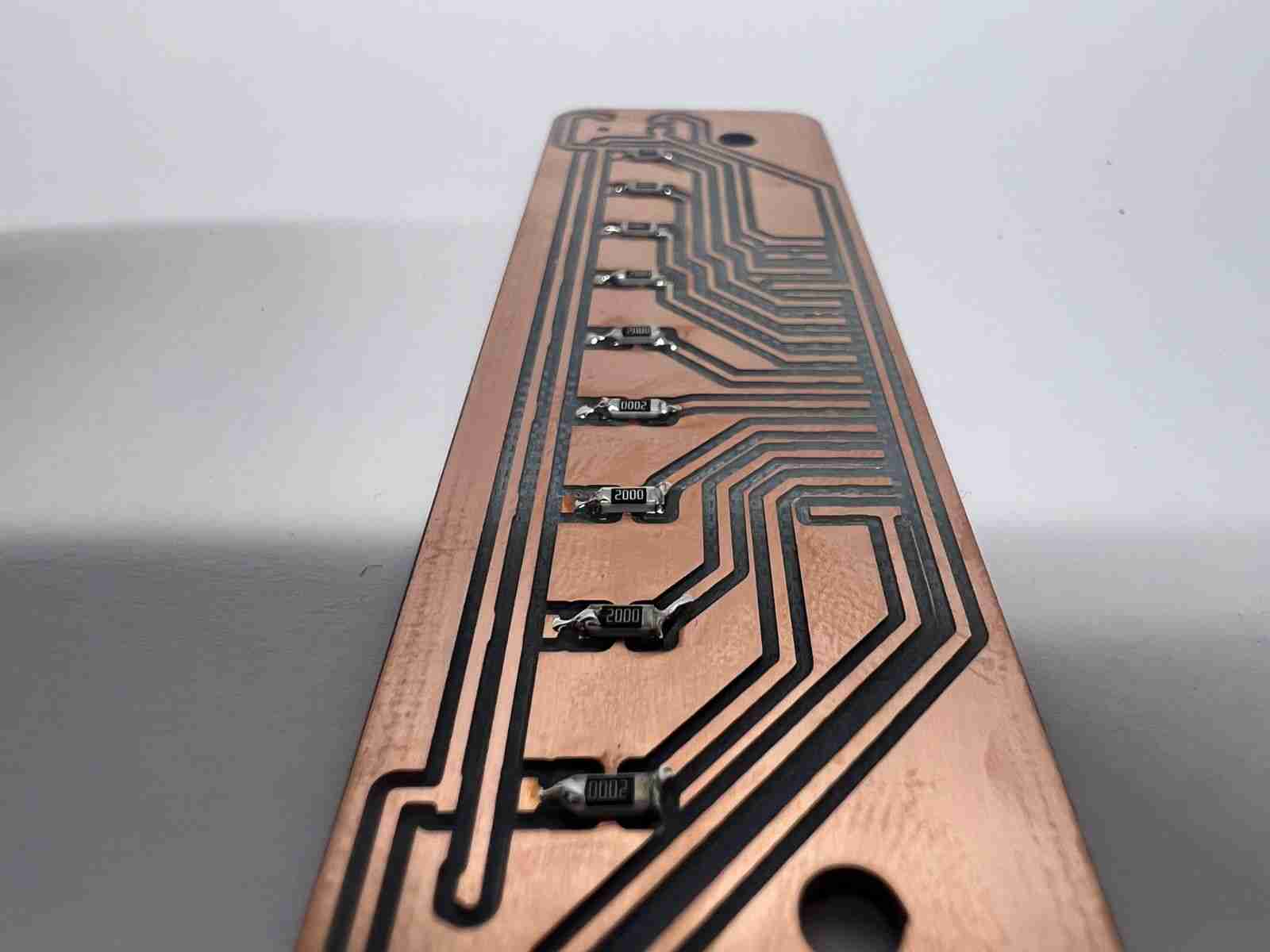
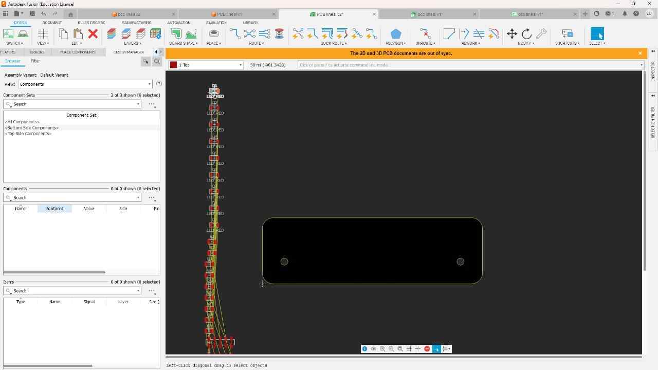
PCB MANUFACTURING
final result
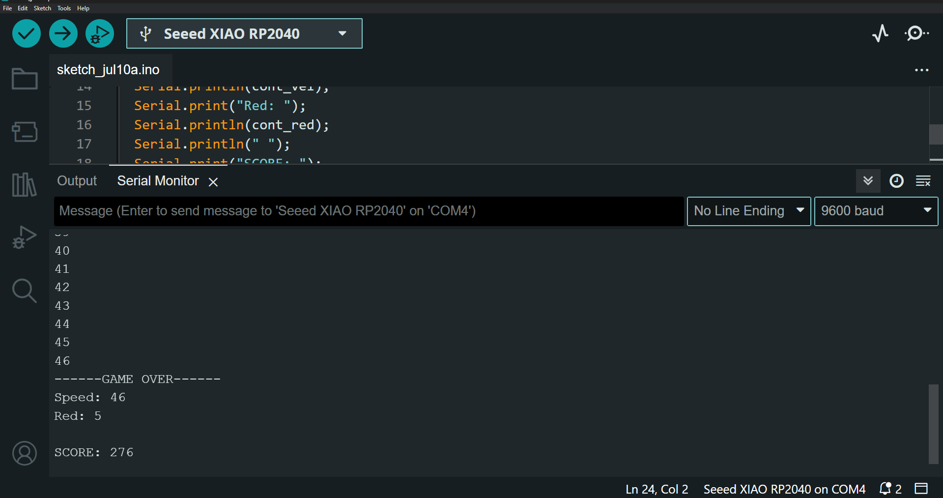
Loading either of the two codes, we would obtain the same result in terms of the operation of the PCB. Within the program terminals we can see how many times the light bounces and the total points that were obtained.


