COMPUTER-AIDED DESIGN
Computer-Aided Design is the use of computer-based software to assist in design processes. CAD software is frequently used by various engineers and designers. CAD software can be used to create two-dimensional (2D) drawings or three-dimensional (3D) models.
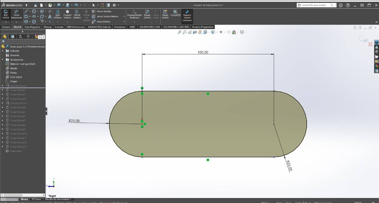
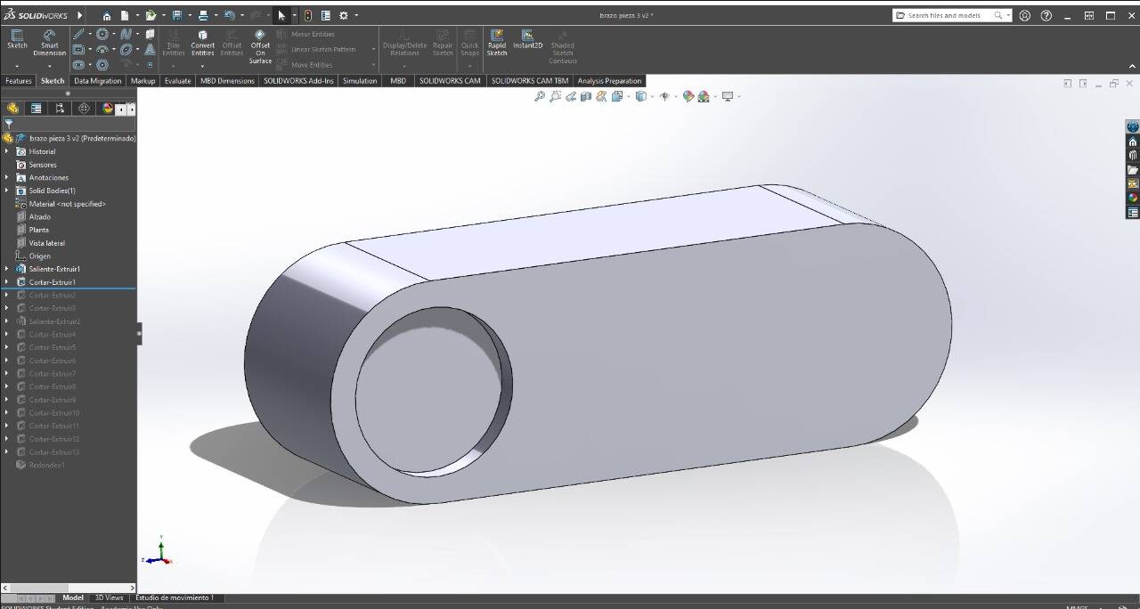
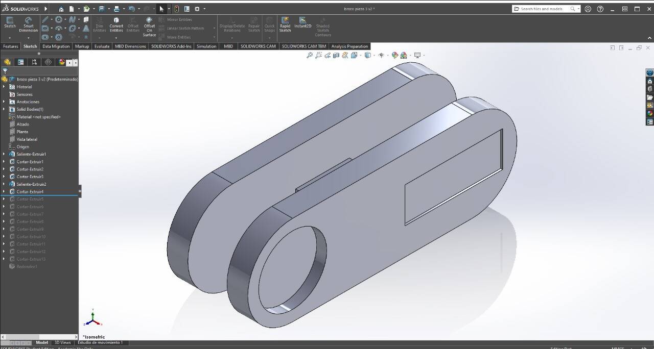
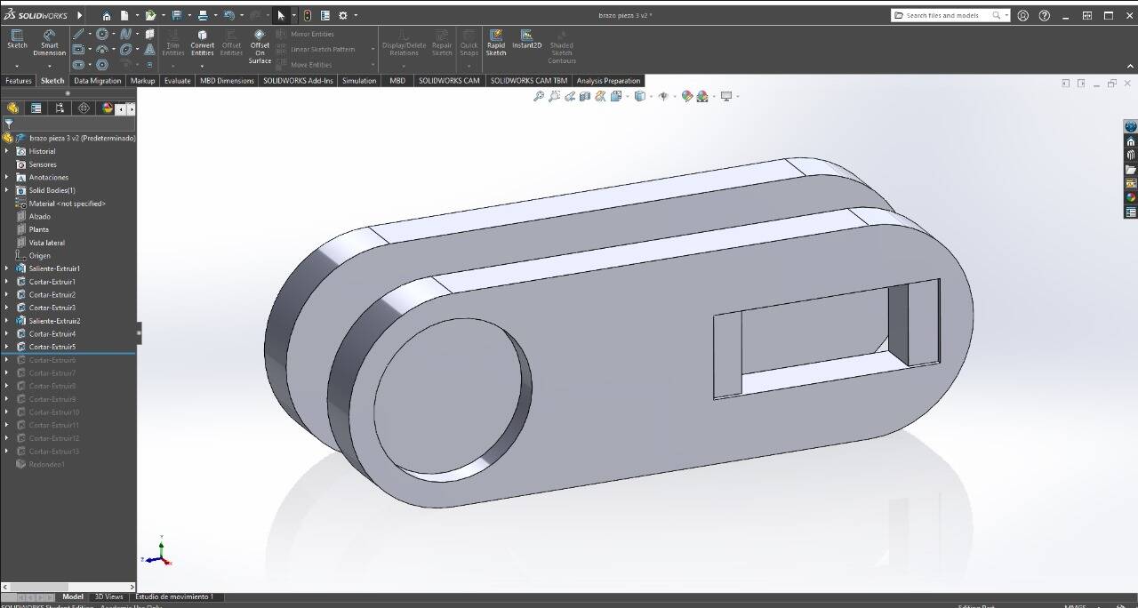
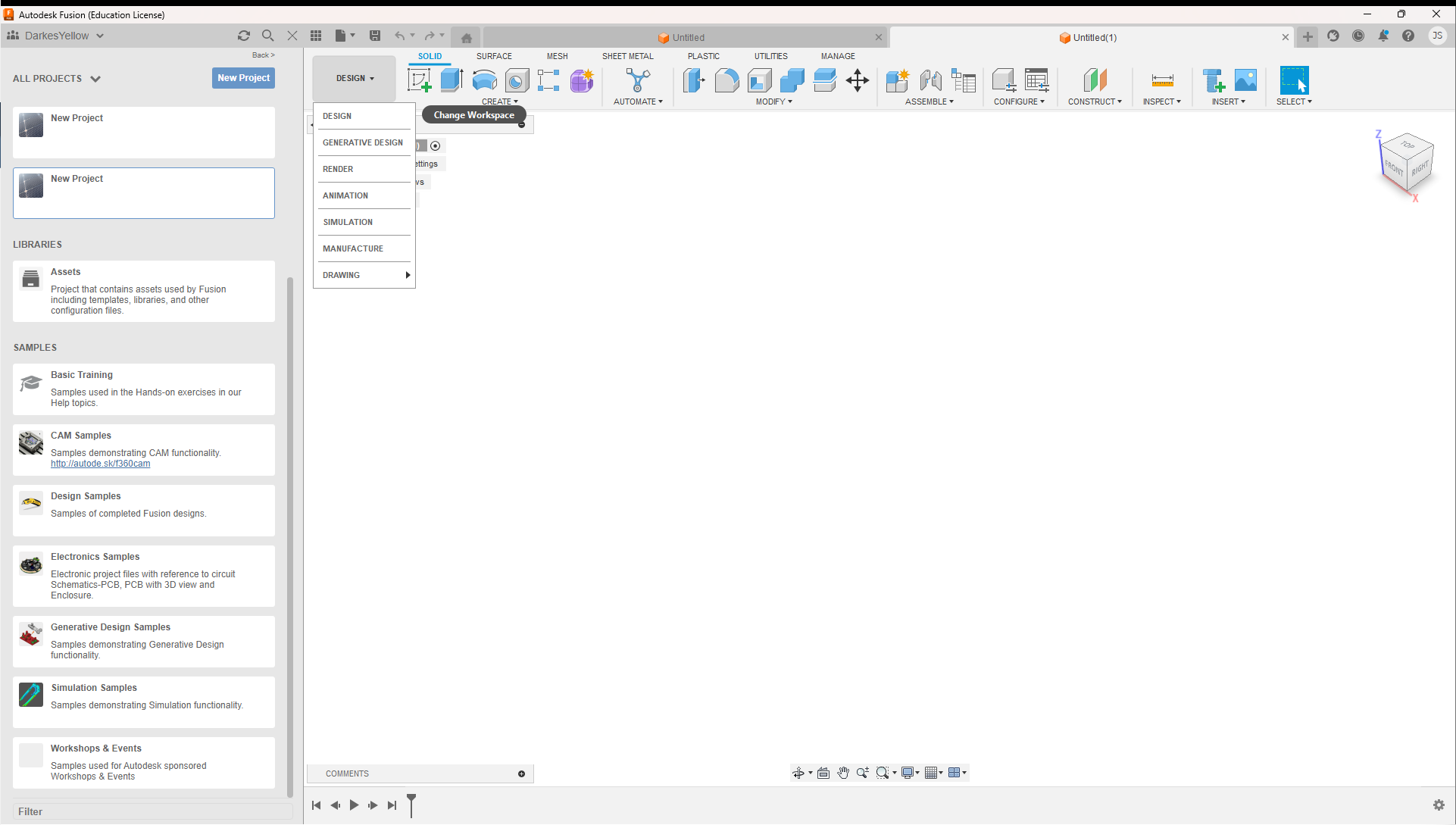
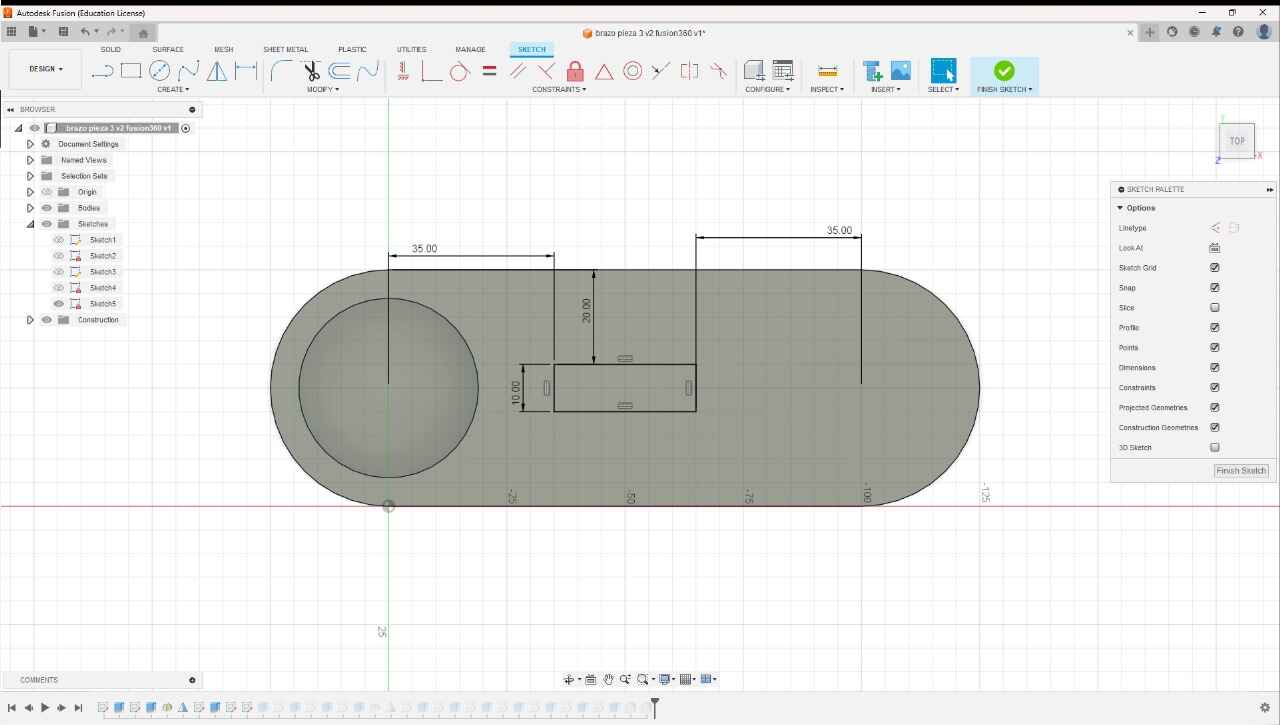
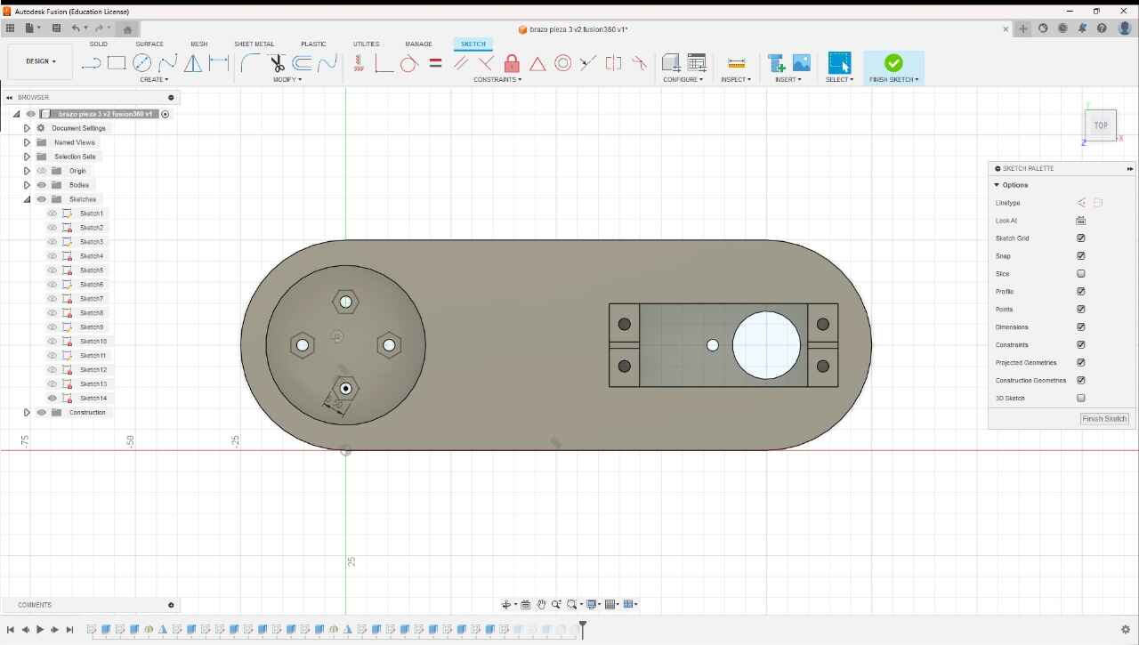
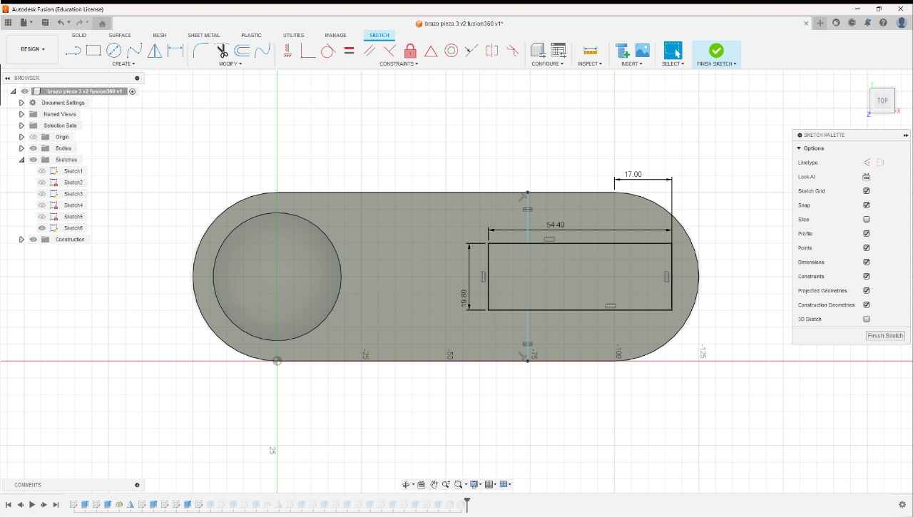
This week, we were introduced to several programs for computer-aided design in 2D and 3D. Among these are programs with different focuses; for 2D, there are programs for photography and vector manipulation, while for 3D, there are various approaches for engineering, filmmaking, animation, architecture, rendering, among others. The idea of this practice is to become familiar with different types of software to work on our final project. Since I haven't yet decided on the construction idea for my final project, I decided to use a 3D model I created as an example for this practice.
Below, I will present some programs that, from my point of view, seemed the most interesting for the development of this course.
3D
- Solidworks
- Fusion 360
- Autocad
- Blender
- Maya
- Onshape
- Catia
2D
RASTER
- Gimp
- Photoshop
- Pixlr
- ImageMagick
VECTOR
- Potrace
- Inkscape
- Illustrator
- Corel Draw
- Sketchpad
- Photopea
- Qcad
AI
- Dall-e
- Bing image Creator
- Chatgpt 4
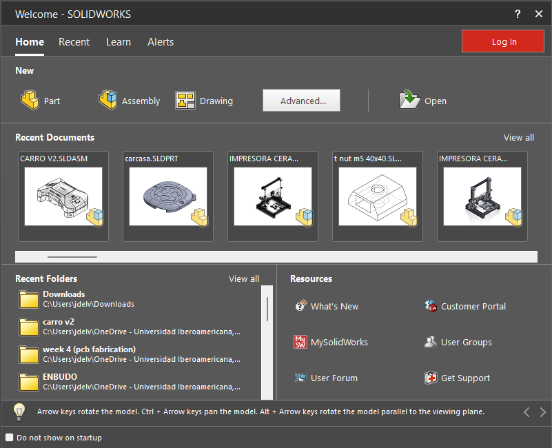
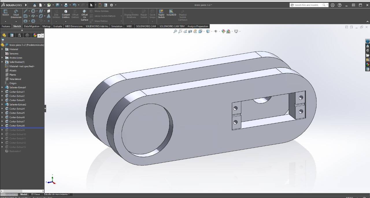
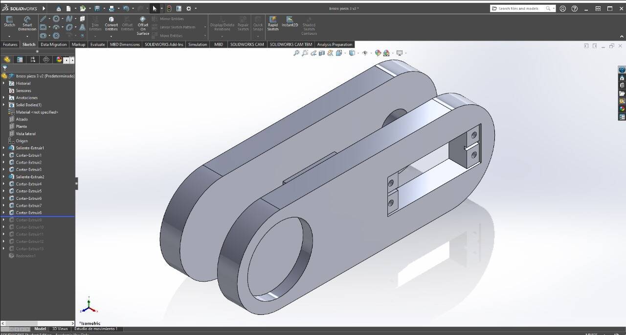
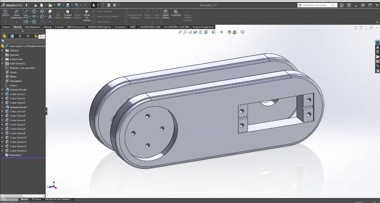
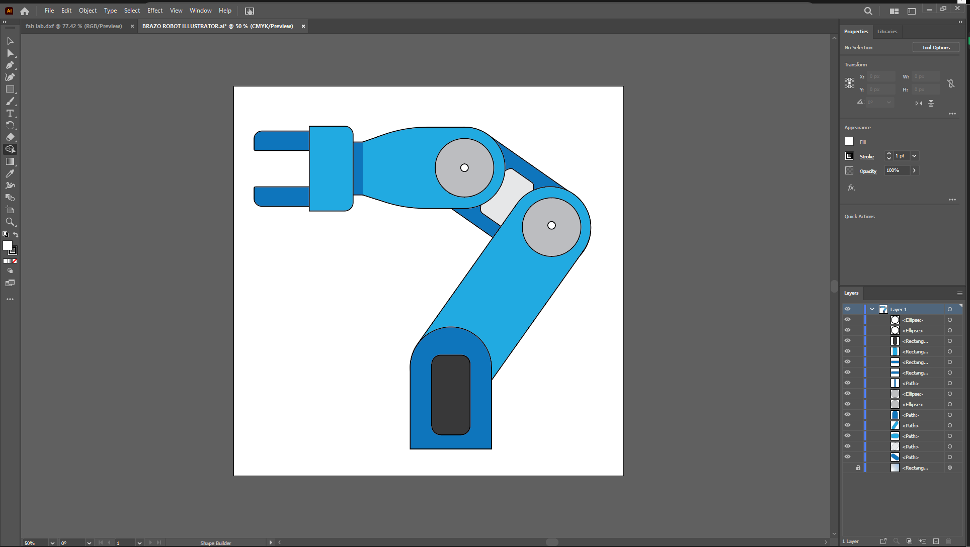
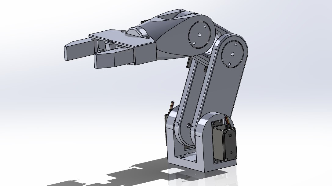
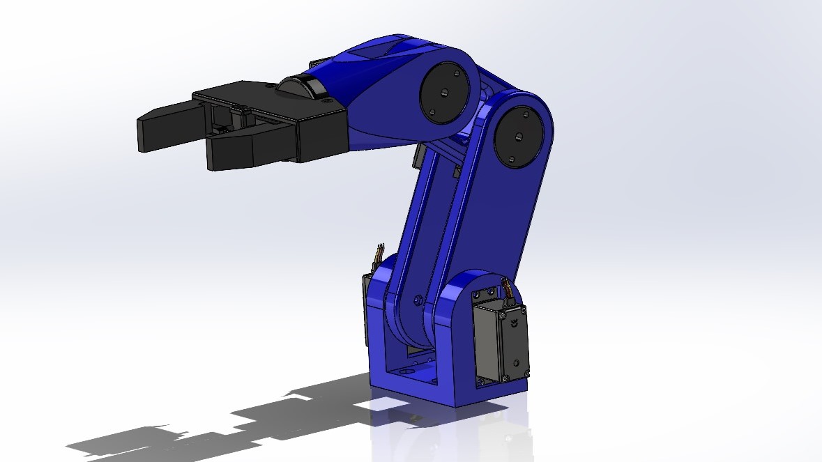
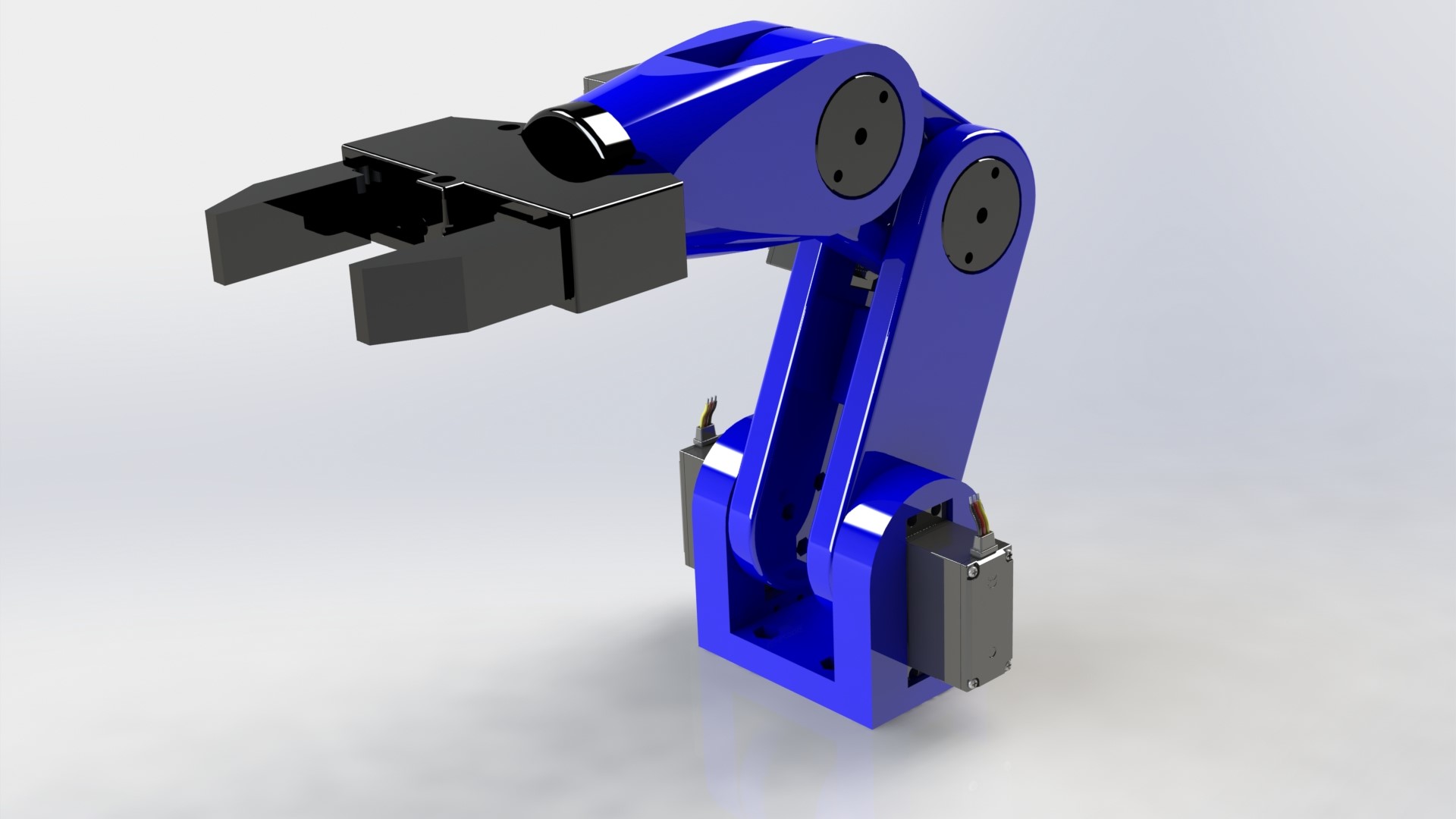
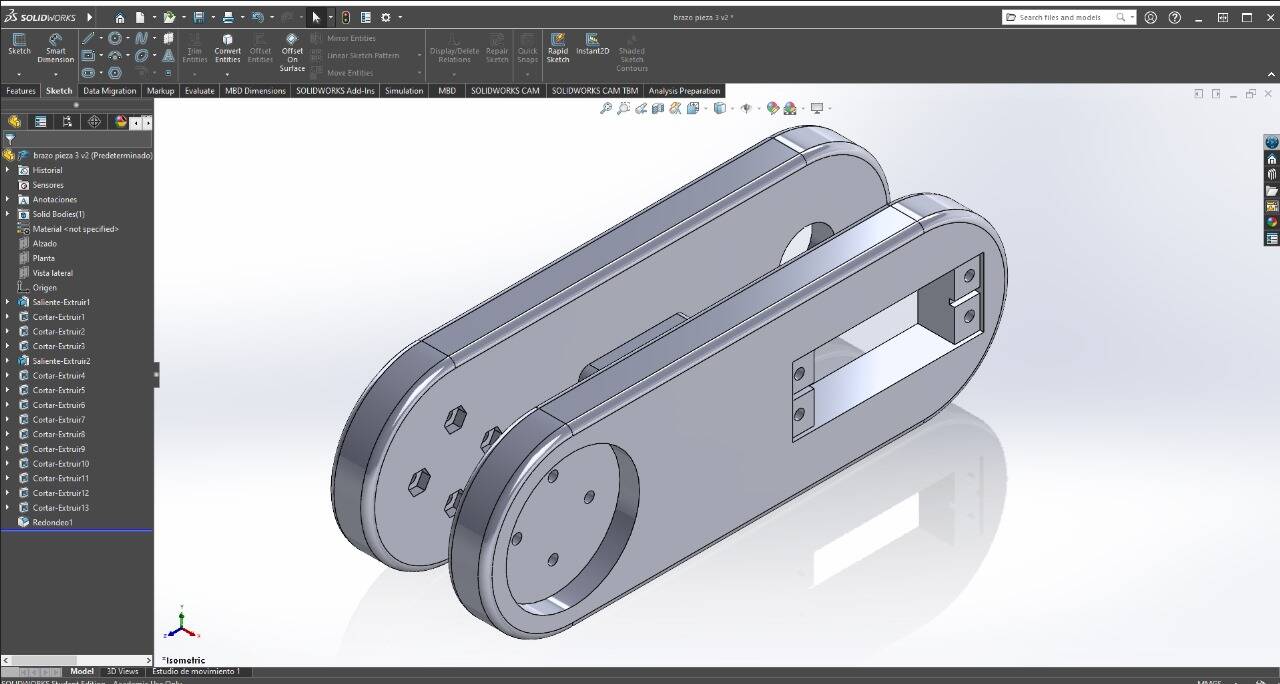
I will use the 3D model of a robot arm that I built 4 years ago as an example. This design was created using SolidWorks, which is currently the 3D modeling program I use the most. Move the 3D model. 3D Model
PROGRAM 3D
SolidWorks
SOLIDWORKS is 3D CAD (Computer-Aided Design) software for modeling 3D parts and assemblies and 2D drawings. The software offers a range of solutions to cover the aspects involved in the product development process. Its products offer the ability to create, design, simulate, manufacture, publish, and manage design process data. 3D Model download
- PARAMETRIC
- BASED ON OPERATIONS
- SOLID AND SURFACE MODELING
- FULLY ASSOCIATIVE

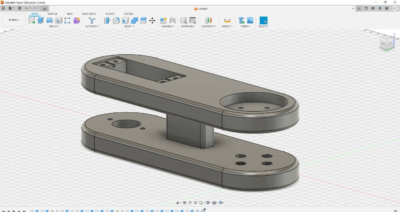
FUSION 360
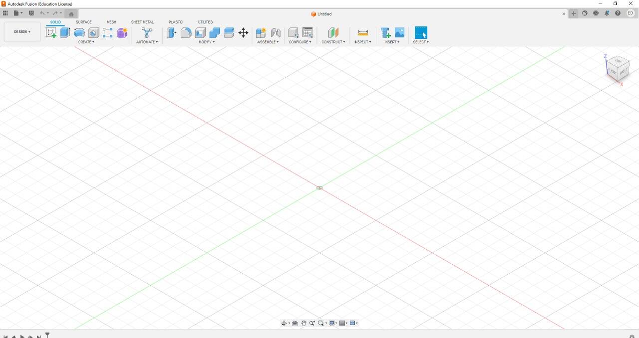
Autodesk Fusion is a cloud-based CAD (Computer-Aided Design), CAM (Computer-Aided Manufacturing), CAE (Computer-Aided Engineering), and printed circuit board modeling 3D software platform for product design and manufacturing. 3D Model download
- FREE OPTIONS
- PRECISE MODELING
- DESIGN, MANUFACTURING, AND ENGINEERING UNIFICATION
- CAD, CAM, AND CAE INTEGRATION
- CLOUD-BASED

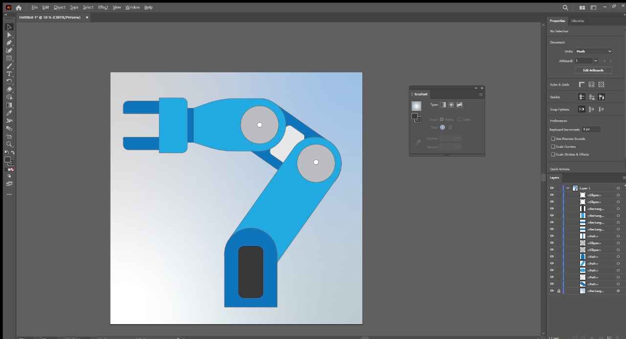
Illustrator
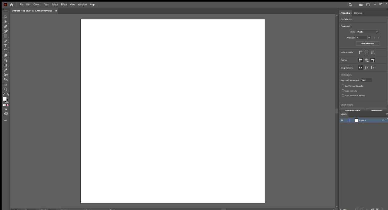
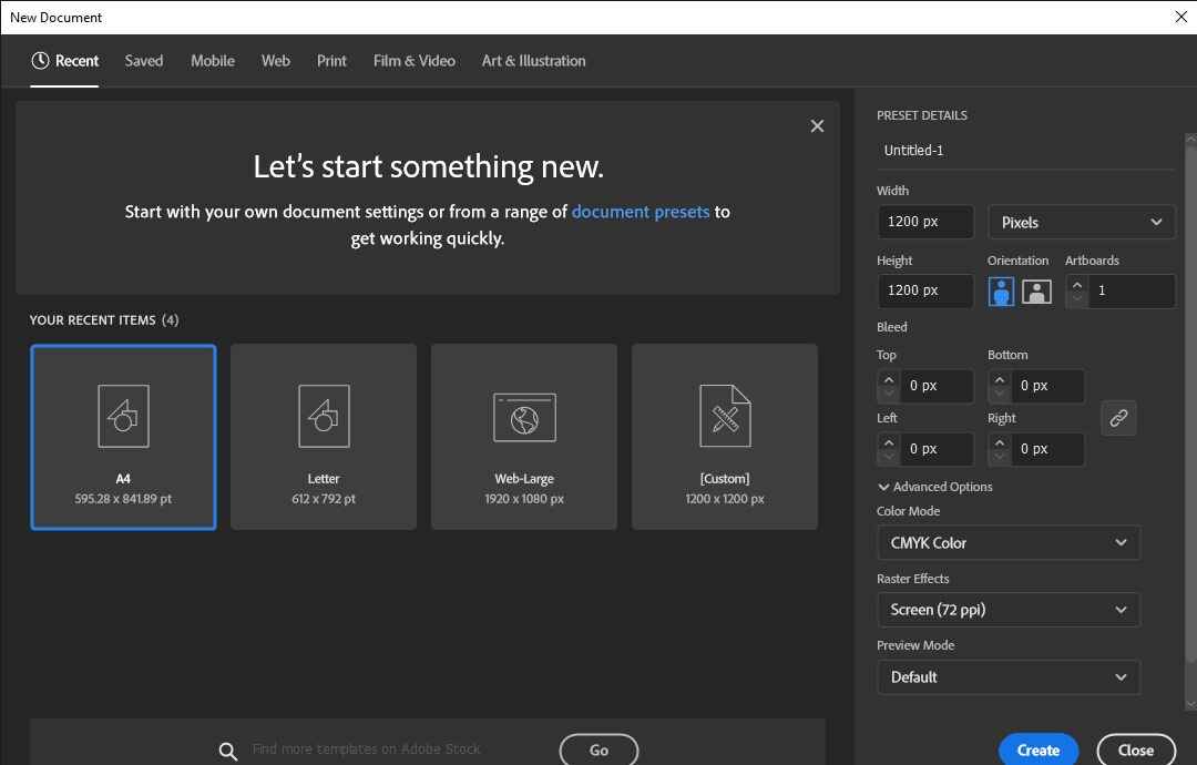
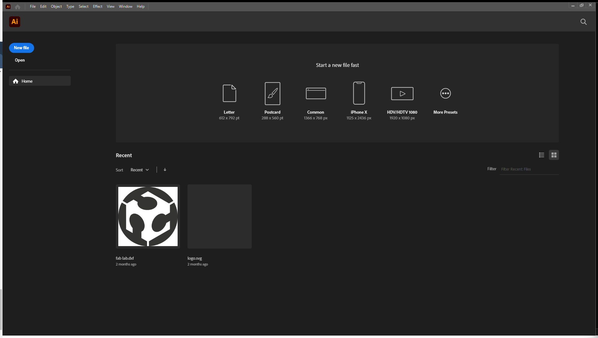
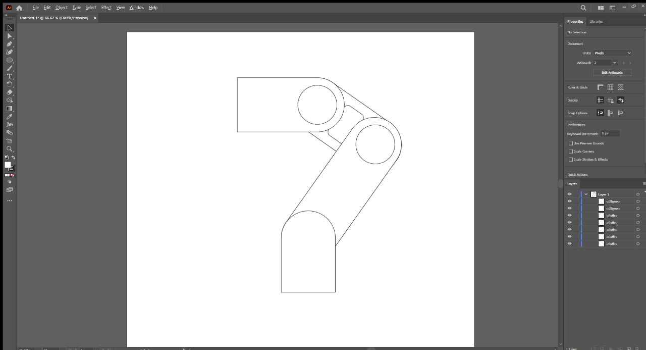
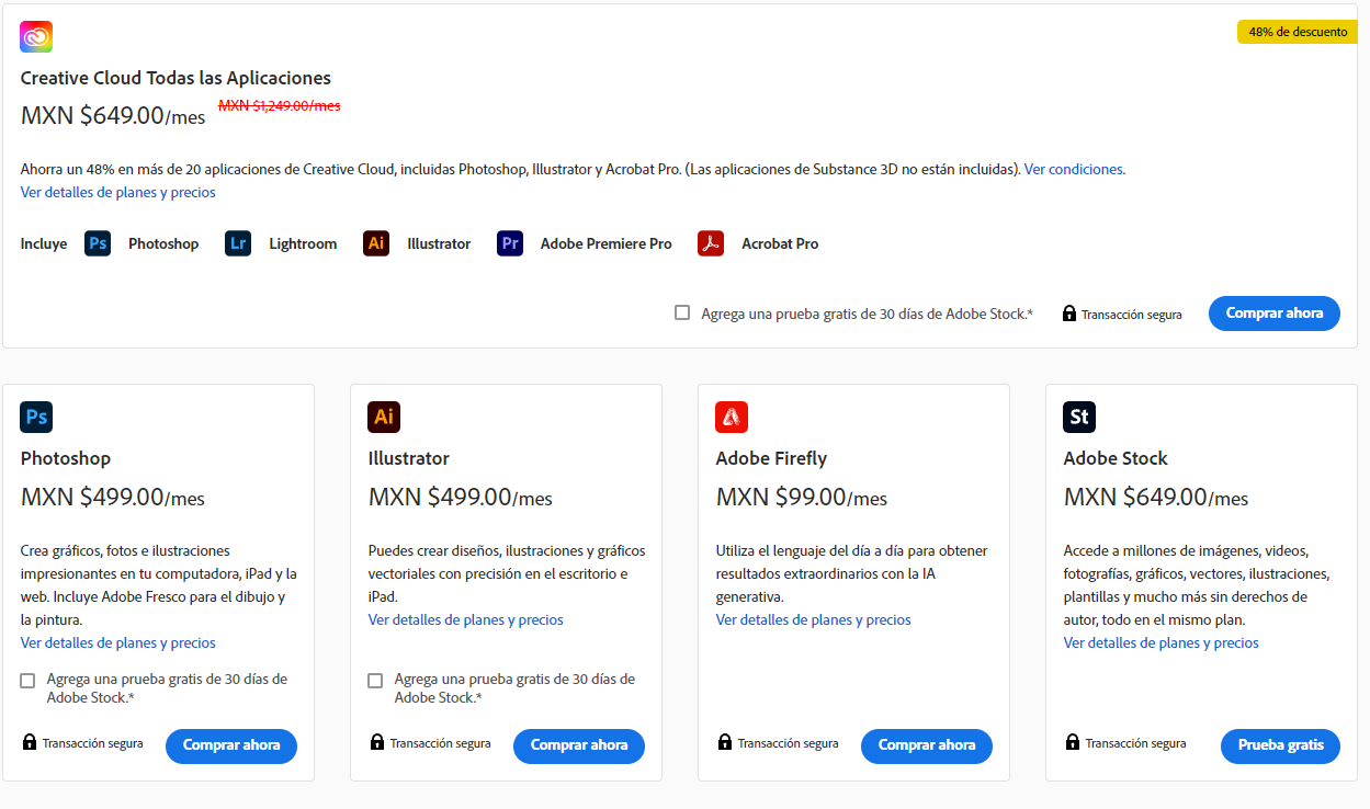
Adobe Illustrator is a paid software for editing vector graphics that is part of Adobe Systems. Adobe Illustrator is a flexible and dynamic tool, it is one of the most used and earliest tools for vector graphics. Drawing download
- SOPHISTICATED VECTOR DRAWING CONTROLS
- ADVANCED TYPOGRAPHY
- PERSPECTIVE DRAWING
- ATTRACTIVE STROKES
- ADOBE COMPATIBILITY
- CUSTOMIZATION

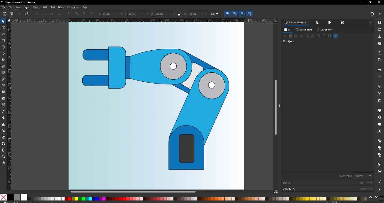
inkscape
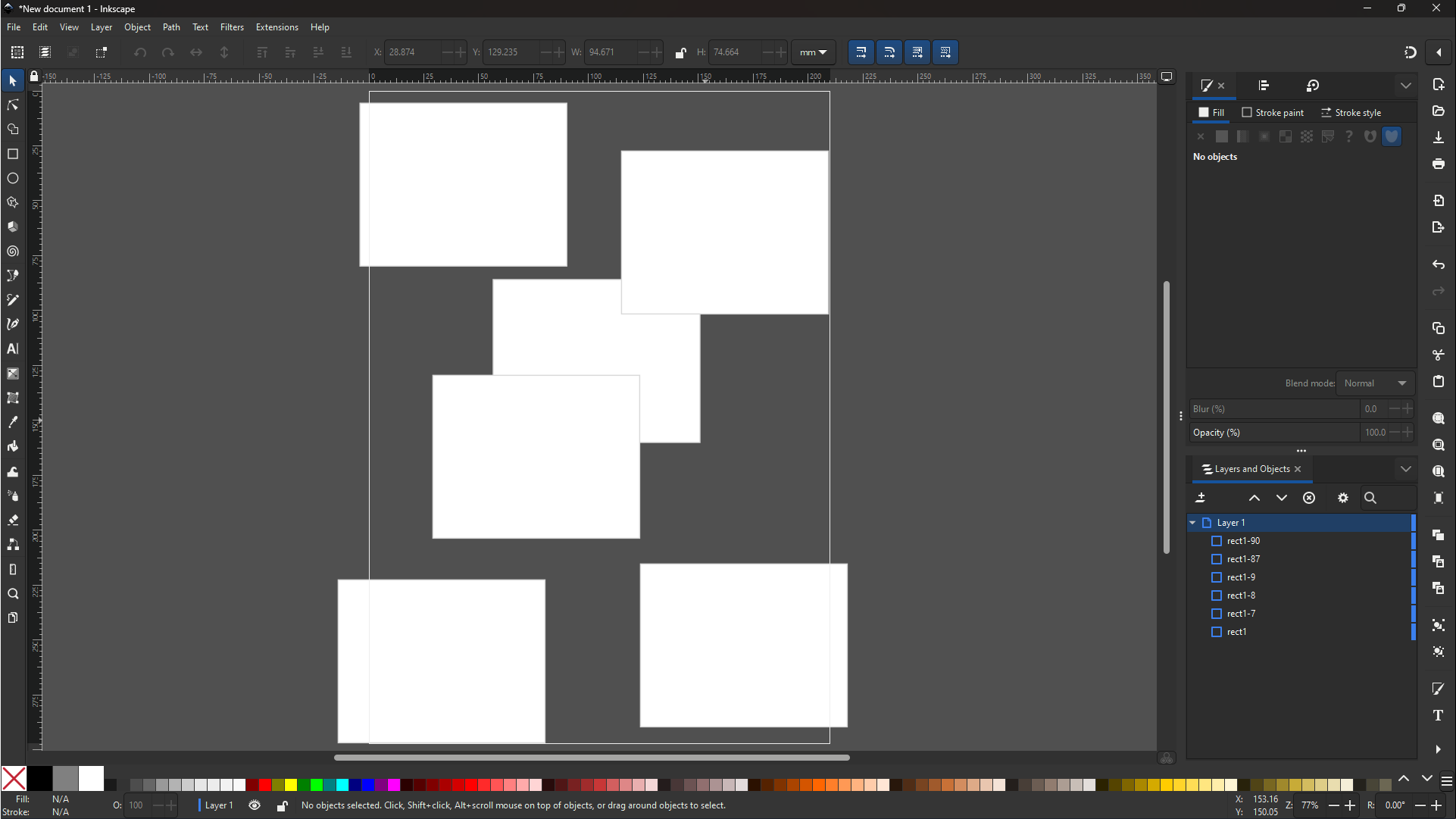
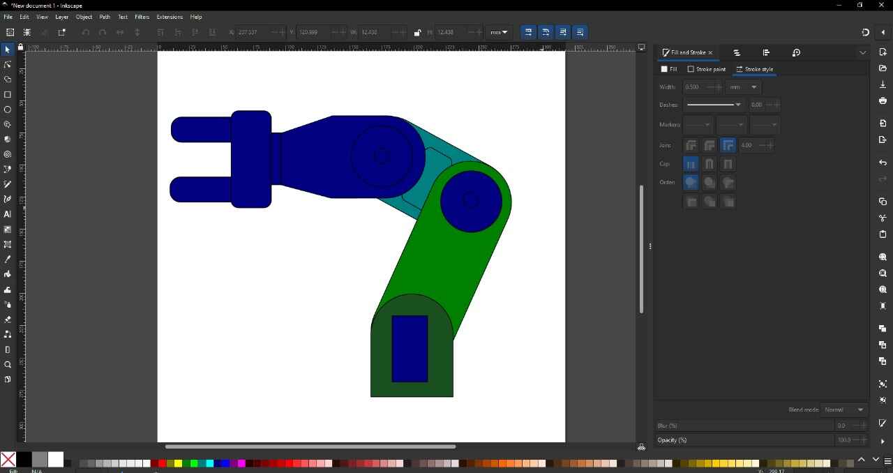
Inkscape is professional quality vector graphics software for Windows, Mac OS X, and GNU/Linux. It is used by professional designers and enthusiasts around the world to create a wide variety of graphics such as illustrations, icons, logos, diagrams, maps, and web designs. Inkscape is free and open-source software that uses SVG (Scalable Vector Graphic). File download
- FREE
- CUSTOMIZATION
- ADVANCED TOOLS
- WIDE VARIETY OF TOOLS
- EASY-TO-USE INTERFACE

my opinion
There are many types of programs for different purposes. Some may be better than others, but what's important is which one you are most comfortable with. Among these programs for 3D modeling, I prefer SolidWorks because it's the program I have worked with the most and have the most experience with. For 2D design, I prefer Illustrator, even though it requires a subscription. For the same reason, I have worked with it before, and I find its tools and interface better suited for me.
In terms of tools and capabilities of the programs, I believe these programs are almost equal in terms of basic or intermediate capabilities. It will depend more on the ability of the person using it to exploit the maximum capacity of each program.
for my project
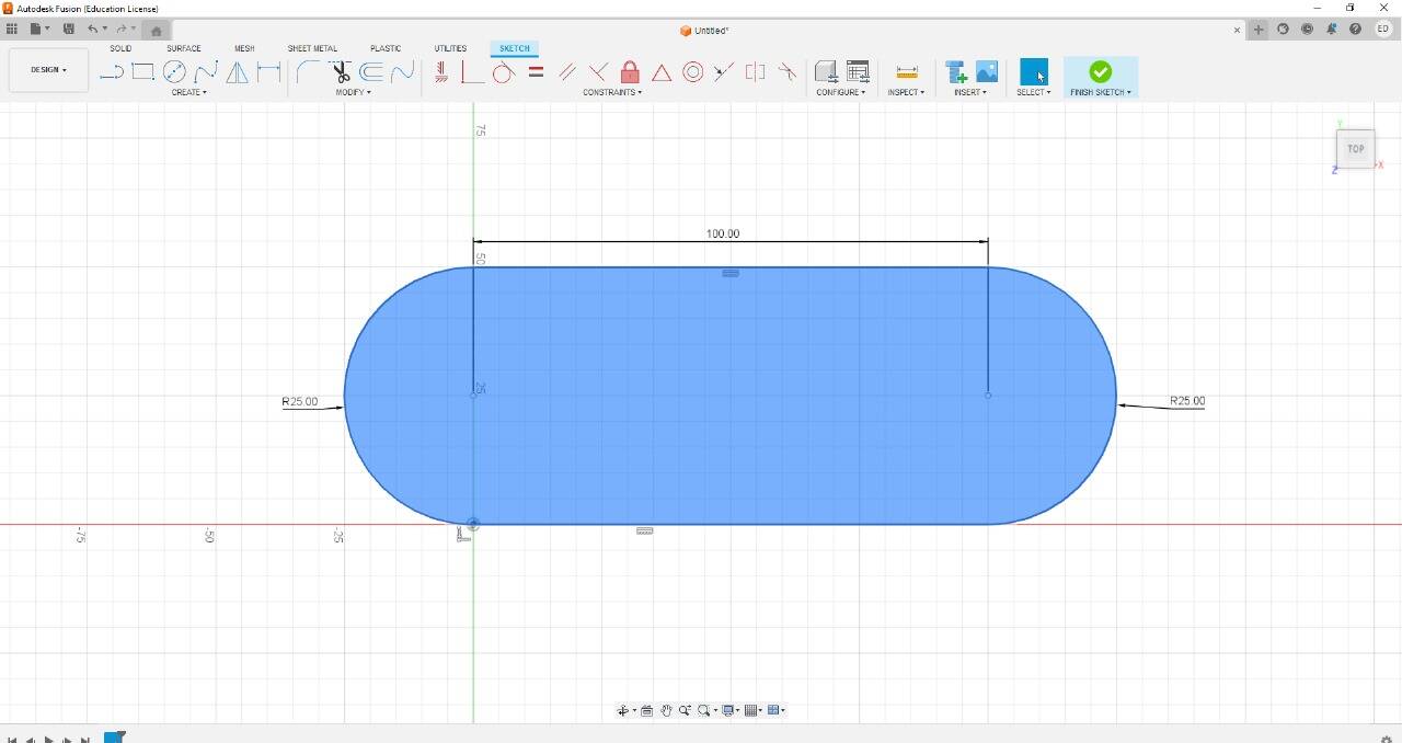
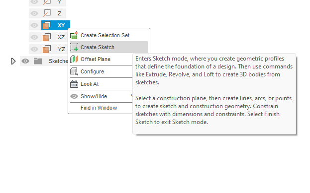
For my project, I will create a basic piece that will be the main support for my profiles. It is a simple piece and does not have much complexity. I started by drawing a rectangle and a central square, which I later extruded. The square has the dimensions of the 40x40 profile.


I made some angled cuts so that the piece doesn't look so square.


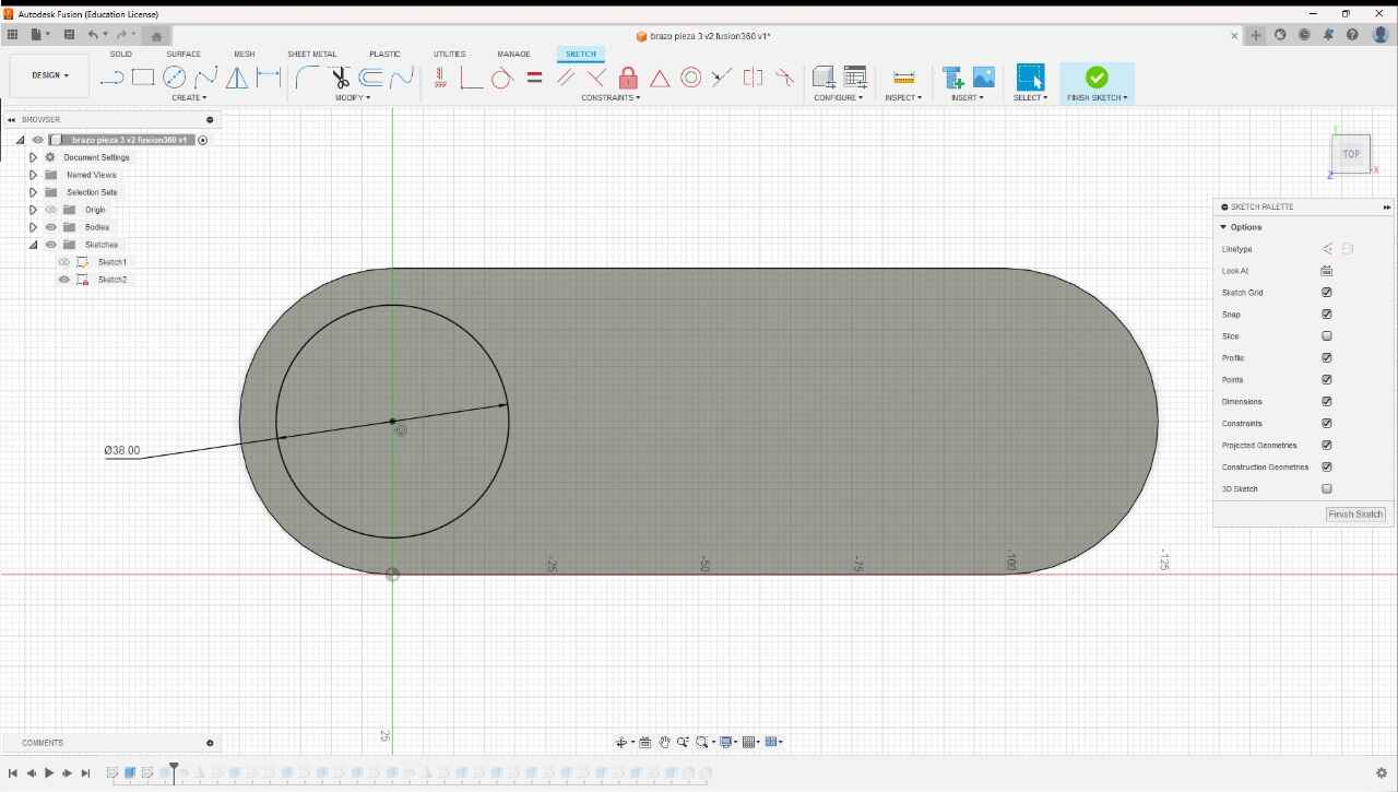
I made some holes in this piece to pass the M5 screws that I will screw into the profile with the help of T-nuts. Additionally, I added a small cut to give it a bit more design.


I also added the holes for the vertical profile. These holes go from one side to the other on all four sides.


To finish the piece, I added some small chamfers to improve its appearance. Here you can see the final piece with color and a render, as well as a 3D view of how the piece turned out.


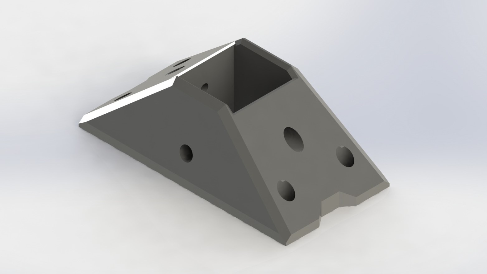
fast render in Solidworks
To quickly and easily create a render in SOLIDWORKS, you will first need to enable the rendering tool in the SOLIDWORKS Add-ins menu, Photoview 360.


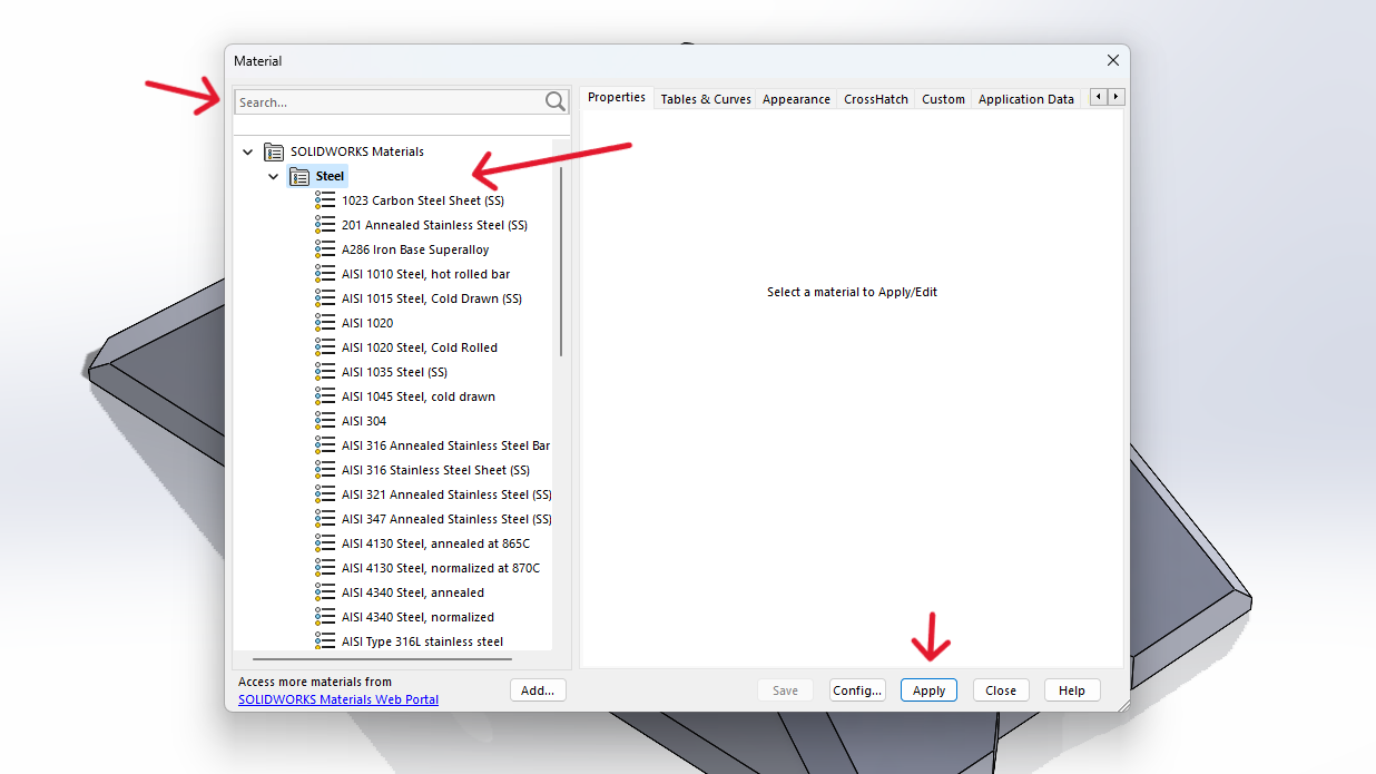
Before starting, you need to assign a color or material to your piece so that it can be visible in the render.
color
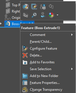
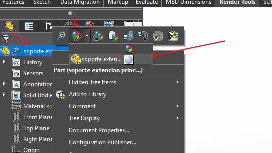
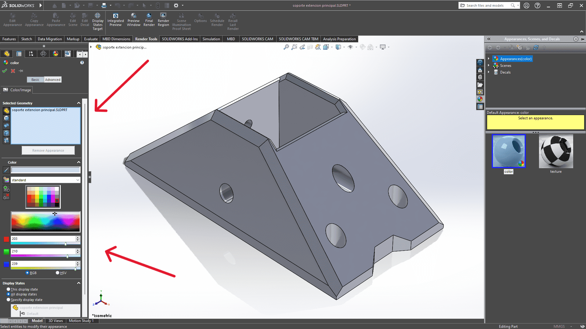
To apply a color, right-click on your piece in the left-side menu, click on the appearance button, and select your piece. A menu will open where you can select and apply the color.
material
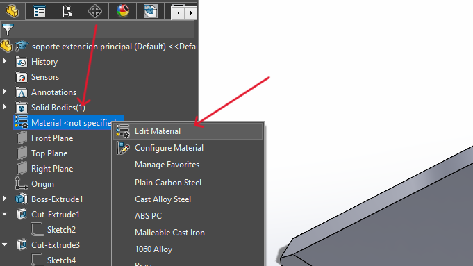
To apply a material, in the left-side menu, right-click on the material, select "Edit Material," and a menu will open where you can search for the type of material. Then, click the "Apply" button.
In the Render menu, click on the Options button, and configure the resolution of your render.


Once configured, click the Final Render button, turn on Perspective View, wait for the render to finish, and then click Save.


