

2. Computer aided design
One CAD to rule them all
So, let´s choose a CAD software to design 2D and 3D parts for the rest of the course and our final project.


When it comes to engineering, which is my field, there are basically 3 CAD softwares that I am familiar with, which are Catia, Fusion360 and Solidworks. Although I have worked with the 3 of them for a considerable amount of time I do have my reasons to chose one over the others. I´ve been using Fusion360 since my freshman year of highschool, and it basically was my introduction to an actual 3D CAD software, I learned all of the basics and a little bit more, so I can say I am somewhat biased since I hold some steem towards this software.
I never really enjoyed Catia, don´t like the interface and changing the constrains is a bigger hassle than it has to be. I did learn it as a subject in my freshman year of college. It is definitely a formidable software, just not to my liking.
So, between Fusion360 and Solidworks, I generally prefer Fusion360, I think it´s more user friendly, cleaner UI and generally a good 3D CAD software to start on and get good projects going. However, as much as I like Fusion, on most fields of engineering, Solidworks is a common standard for it´s quality, power and versatilty. So I would consider it better to just stick with a well known software and learn the most out of it as much as I prefer other softwares. So Solidworks it is. However, the best software for you is the one you like best and fits you accordingly (most of the times...)
Designing with Solidworks
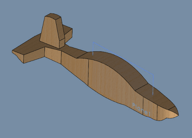
So, let´s do a 3D approximate model of our final project: a rough plane Fuselage:
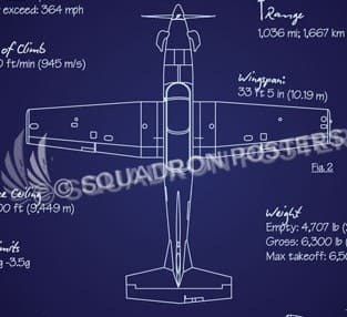
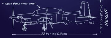
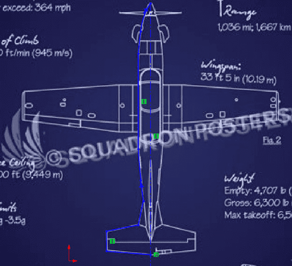
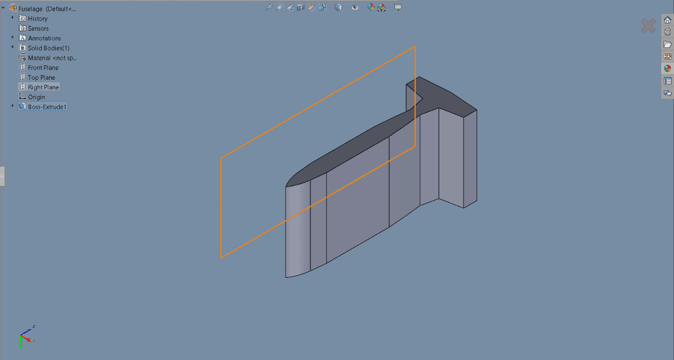
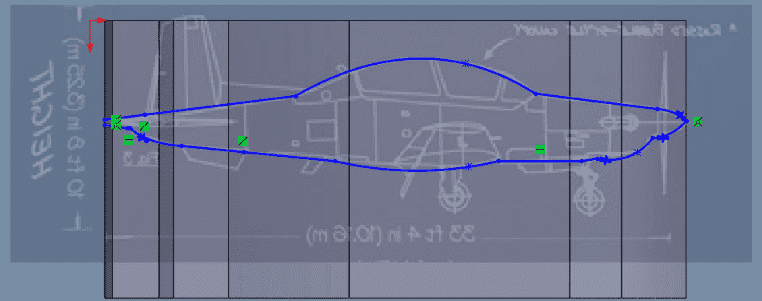
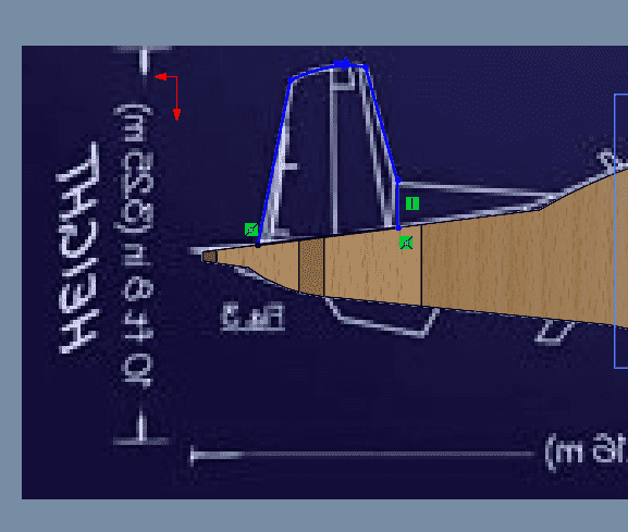
Firstly, we are gonna take a 2D outline of a plane to have the right proportions for width, height and length, for my case I choose a T-6 Texan II.
To draw a proportionate fuselage, we are gonna need the top and side view blueprints of whatever we are gonna sketch, for my case, I choose this ones:
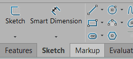
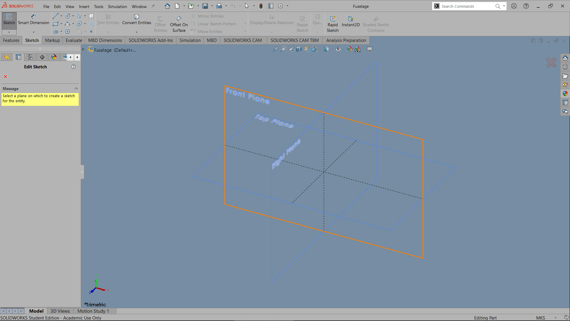
We are going to open a a new file on Solidworks, on the top left we should see the sketch tab, then the sketch button
That should give us 3 different planes to sketch on: Top, Front and Right plane, I´ll be starting drawing with the top view blueprint, so let´s choose the top plane
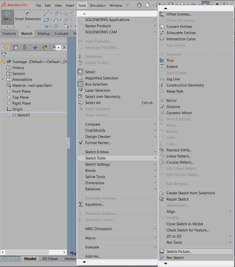
To paste our blueprint, go to the Tools tab -> Sketch Tools -> Sketch Picture. Then select your top view image
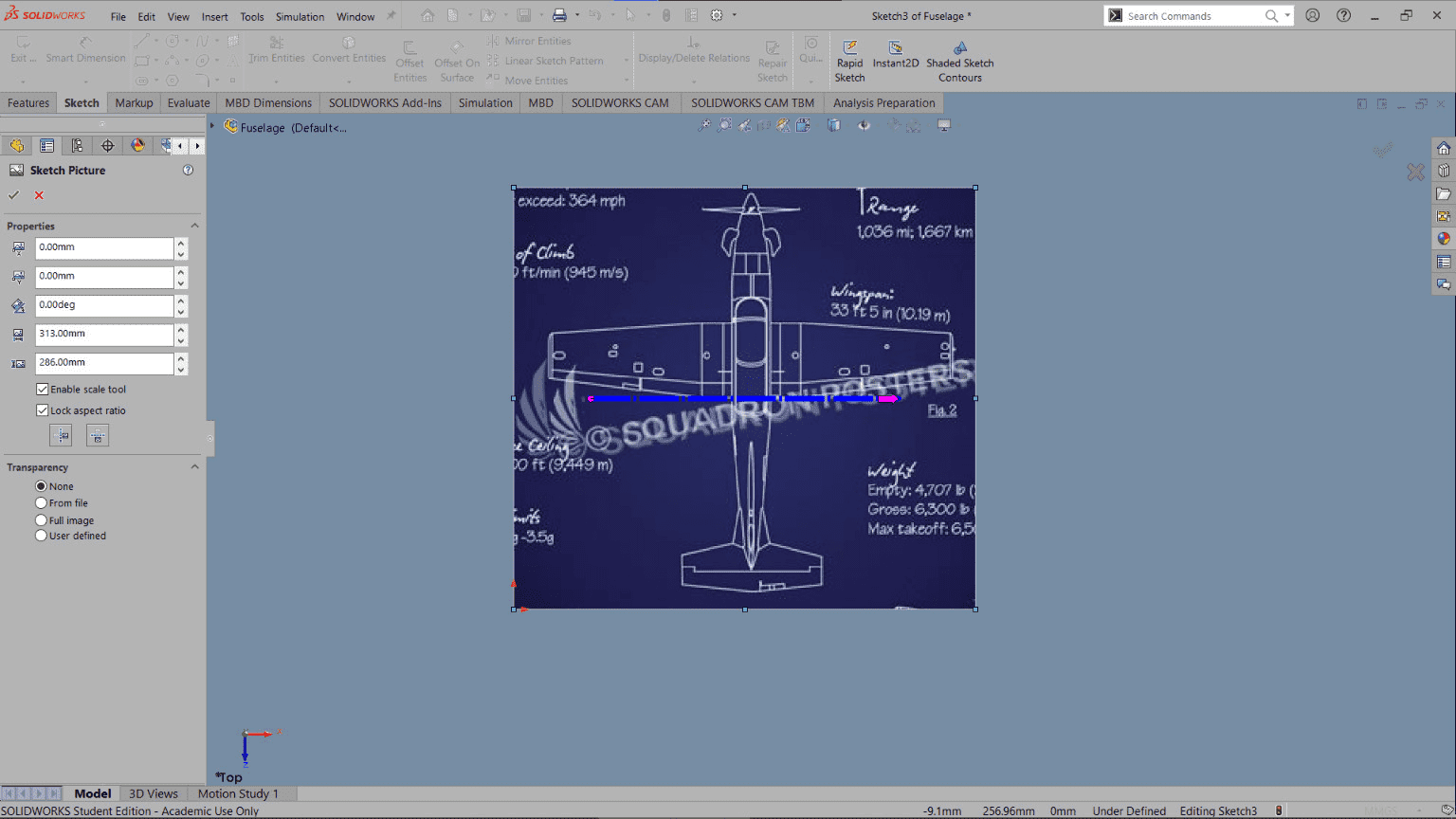
This is how it should look like:
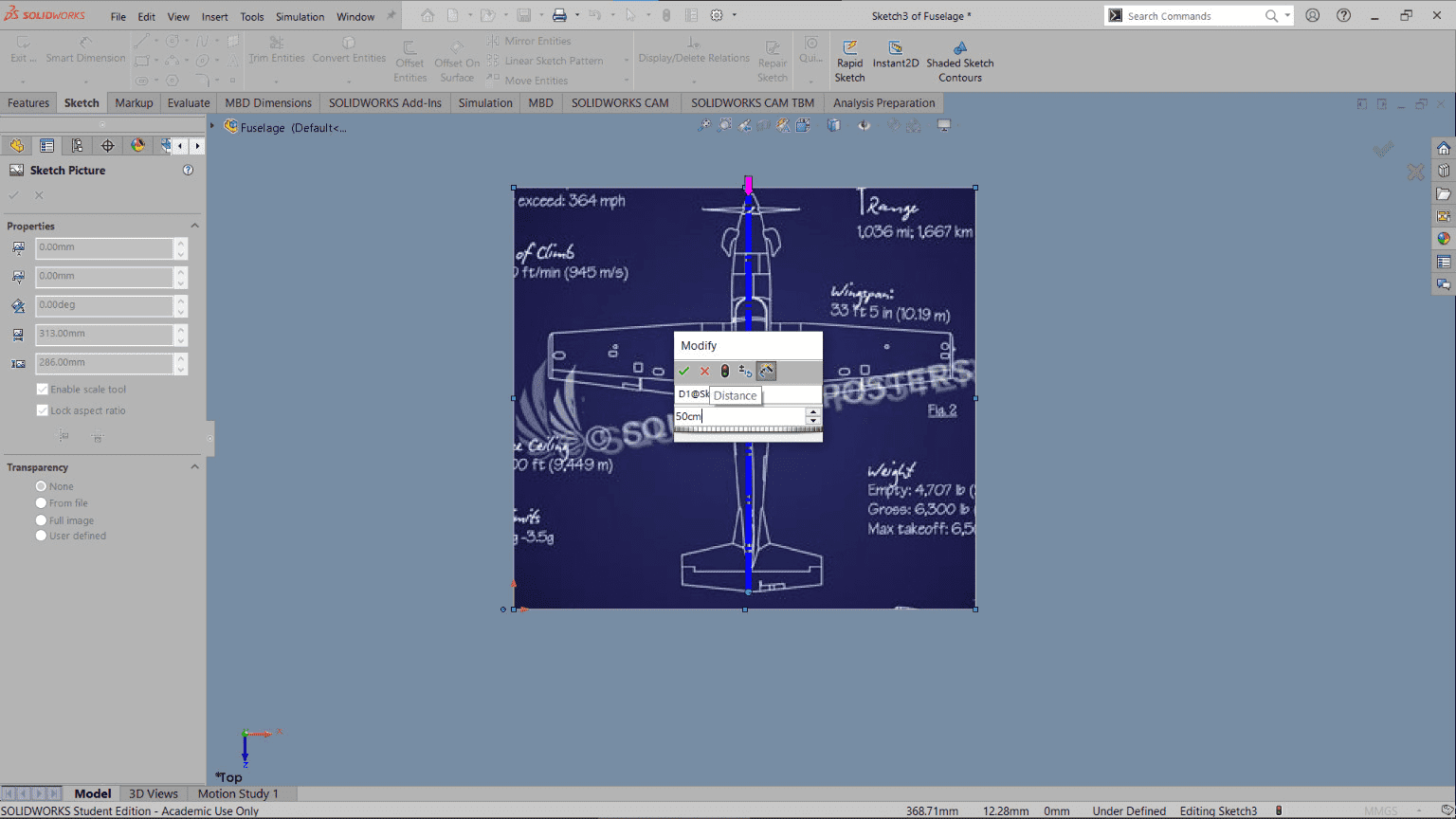
To give it the dimension we want our actual drawing to be, align the blue dotted line in a given dimension, I want the plane to be 50 cm in length. A pop up tab should appear once you aligned your line, enter the dimension
Now, the fun part...? Time to actually draw and sketch. We have 3 basic tools at our disposal to draw with: the straight line; as it sounds, it justs draws a straight line between 2 given points. Spline: a curved line given between 2 points. And finally, the construction line; this one won´t actually appear in the drawing, it´s more of a reference line we can use to mirror our sketch, I´ll get to that shortly.
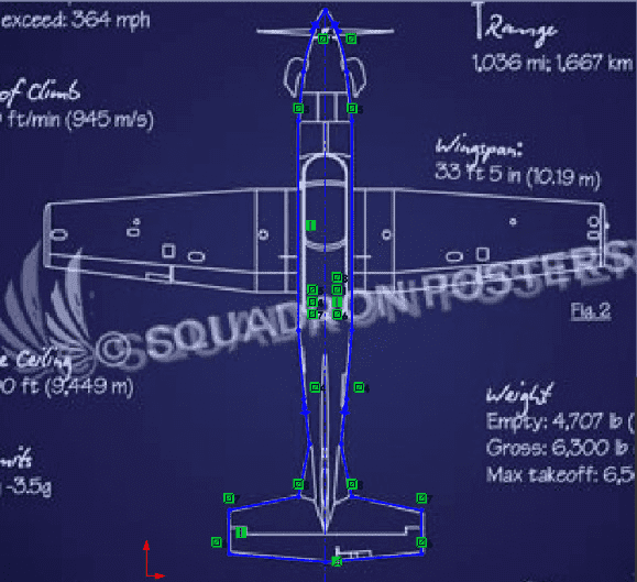
In my case, I drew half the plane and added a construction line across, here it´s how it looks:
Now, the mirror opperation works by replicating a sketch alongside a given reference, in our case the construction line
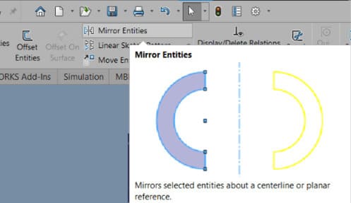
By selecting our lines and giving it the reference point, the mirror is complete and it looks like this:
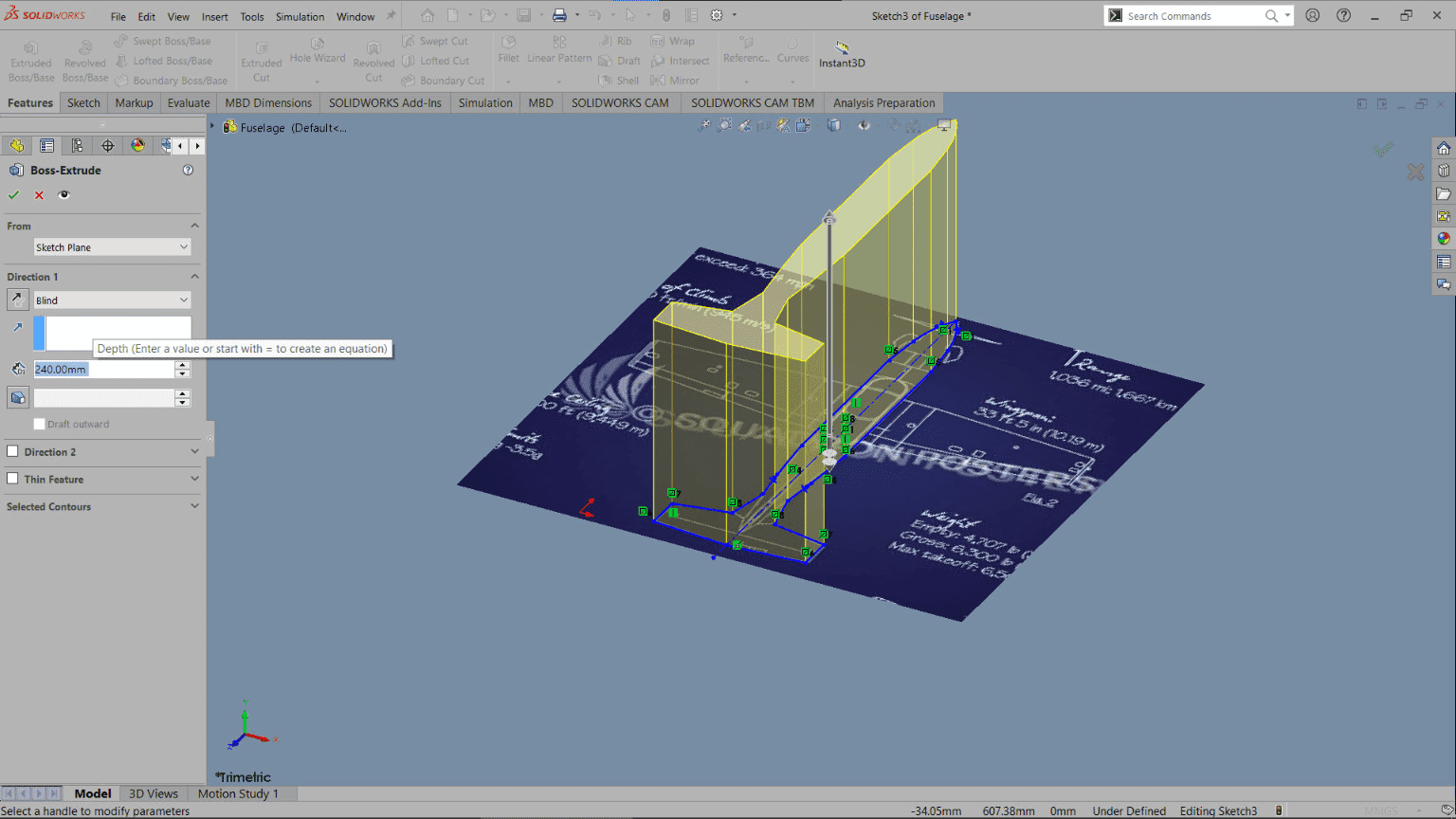
The next operation we have is extruding. We are gonna take our 2D sketch and give it a height and volume. I gave it an arbitrary height, you will see why in a bit. Just tall enough to fit the other image sketch on it.
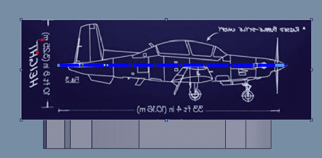
So, we need to sketch again, this time parallel to our extrude we just did, but for that we need another plane to sketch on. To add a new one, we go to the Reference tab, then to Plane
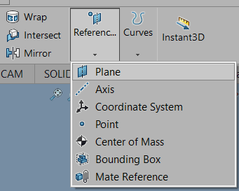
Add it parallel to the extrude
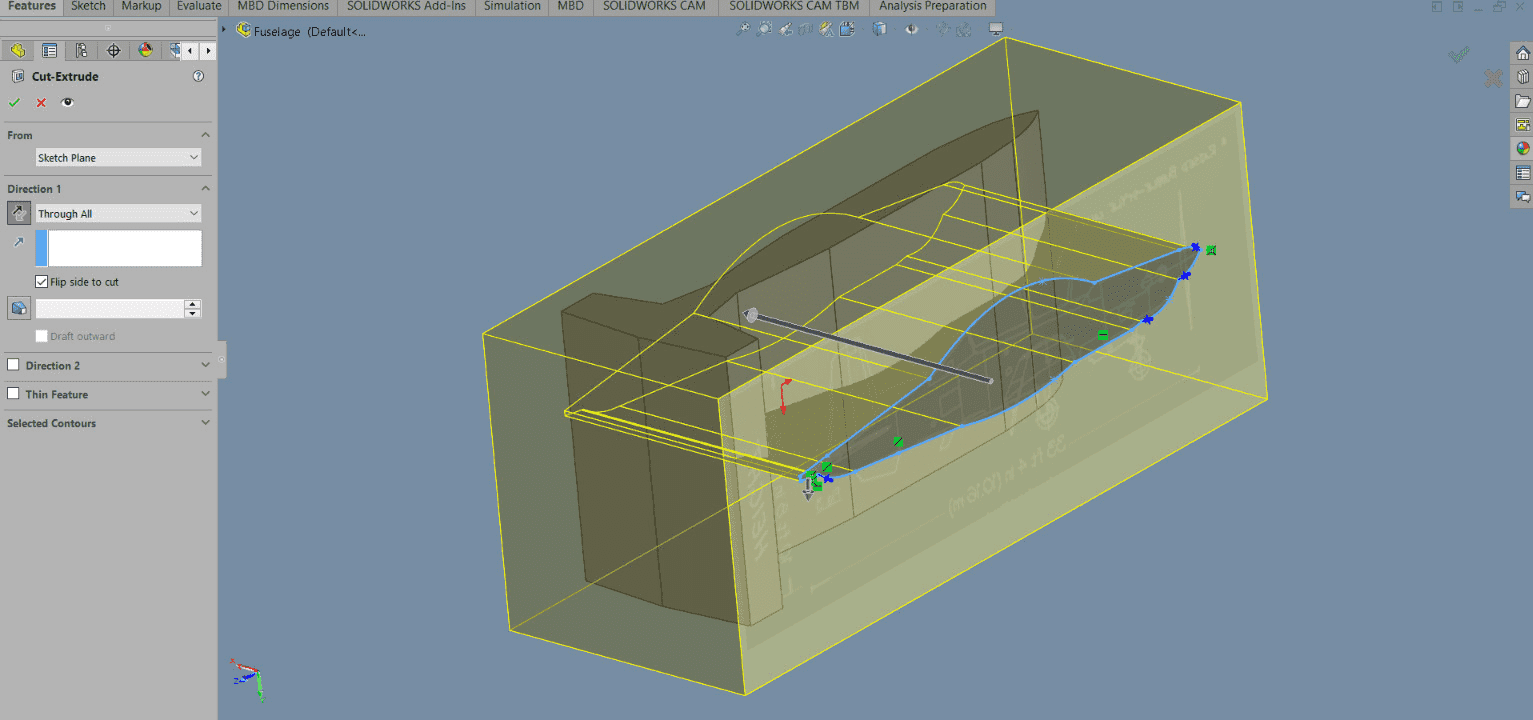
Add your image and give it the dimension like we did before
To correctly align it with the extrude, we can change the transparency in the left side menu when selecting the image, this make it easier to have an (almost) perfect match.
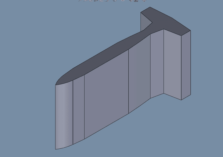
Again, we sketch the image with our drawing tools
Now, instead of extruding we are using the extrude cut feature and select the "flip side cut" on the side menu, then also the "Through all" direction
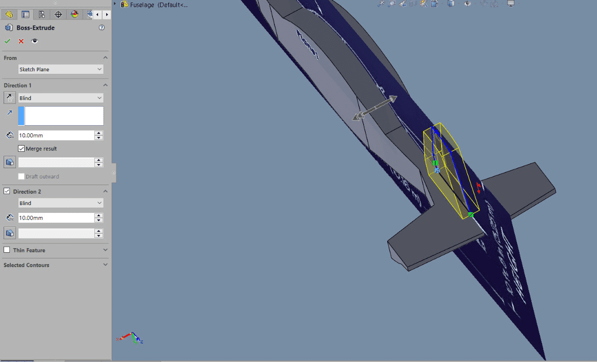
But wait, we are missing the rudder... For that we add yet another plane. This time we select it between 2 parallel faces in the fuselage, this will position the plane exactly in the middle of our figure.
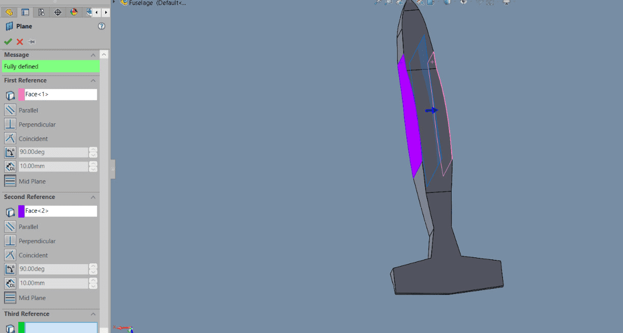
We use the image we previously had from the side view to sketch the rudder
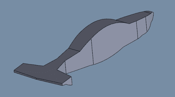
We extrude the selected sketch but this time in 2 directions with equal dimensions, so it extends to both sides of the plane equally.
Let´s give it a less boring finish. How about a wood texture? We can select whatever material we want our model to be on the left side tree menu, in my case I choose balsa wood.
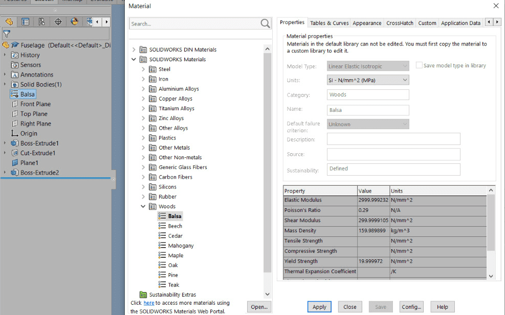
And here we have the final result:
3D Model
Trying Fusion360 Aswell
Let´s try my favorite software, here I will do a much simpler piece, but it gives me the oportunity to work with some interesting tools.
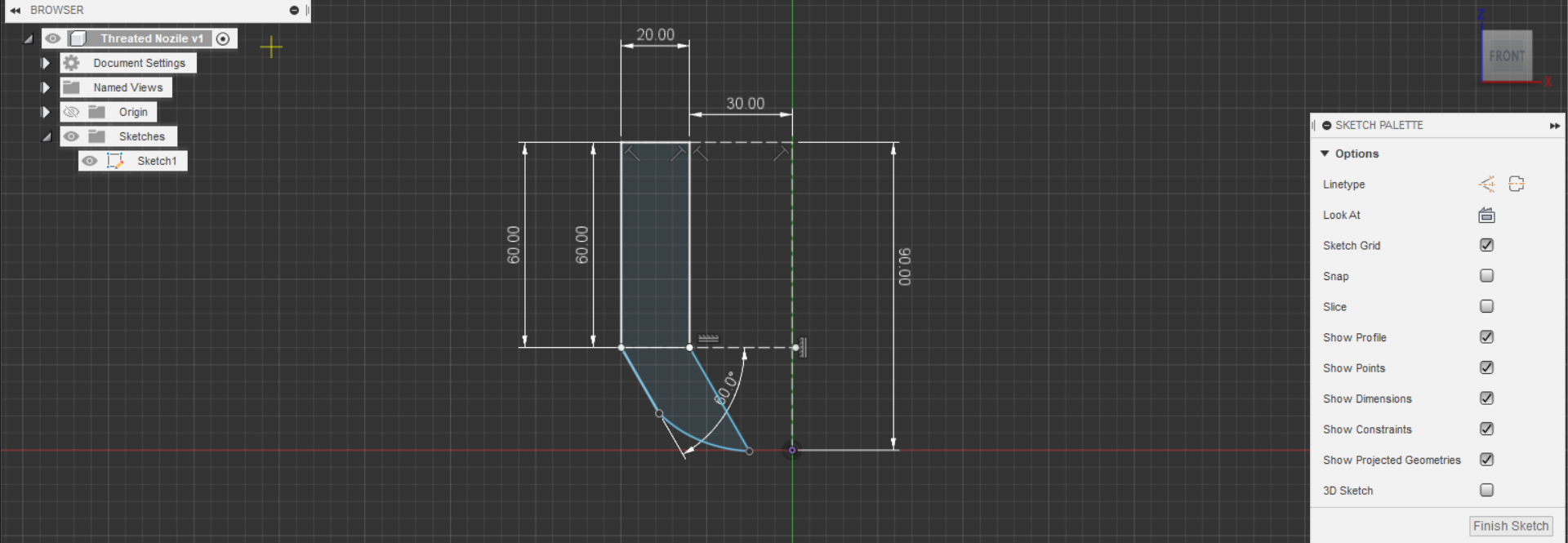
We start the same way, choosing a sketch plane, this time I will be using the front plane
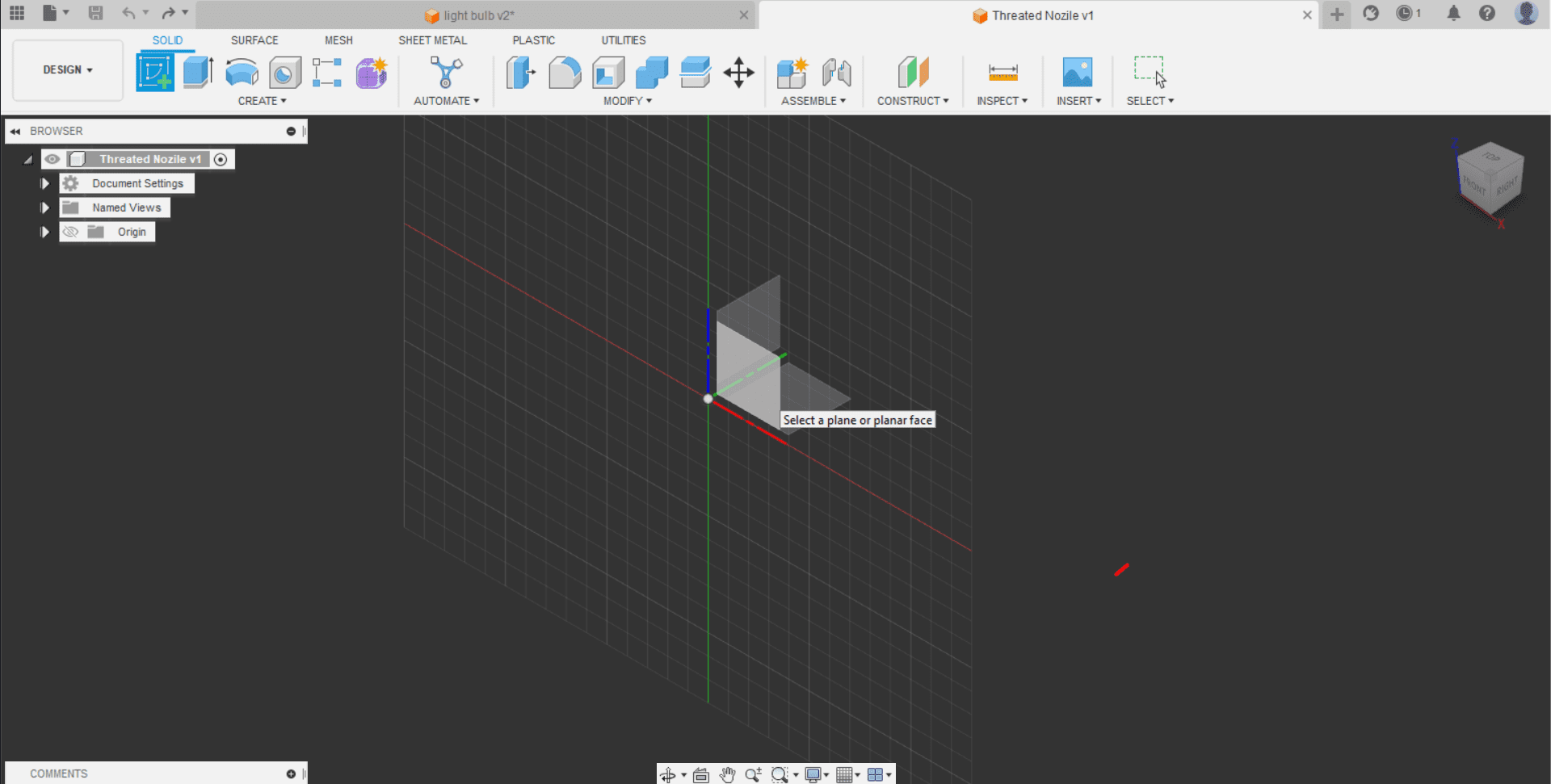
Now, the tools are basically the same, we have the straight line, which we can toggle into a construction line, a spline and much more. Here I sketched a threaded nozzle with the same tools, drawing only half aswell with the construction line in the middle

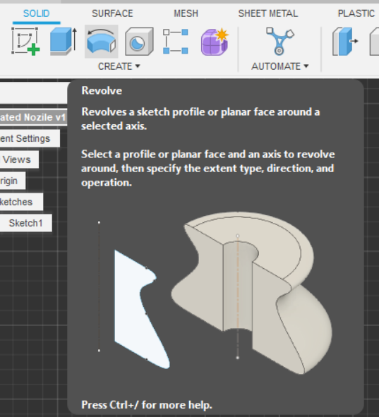
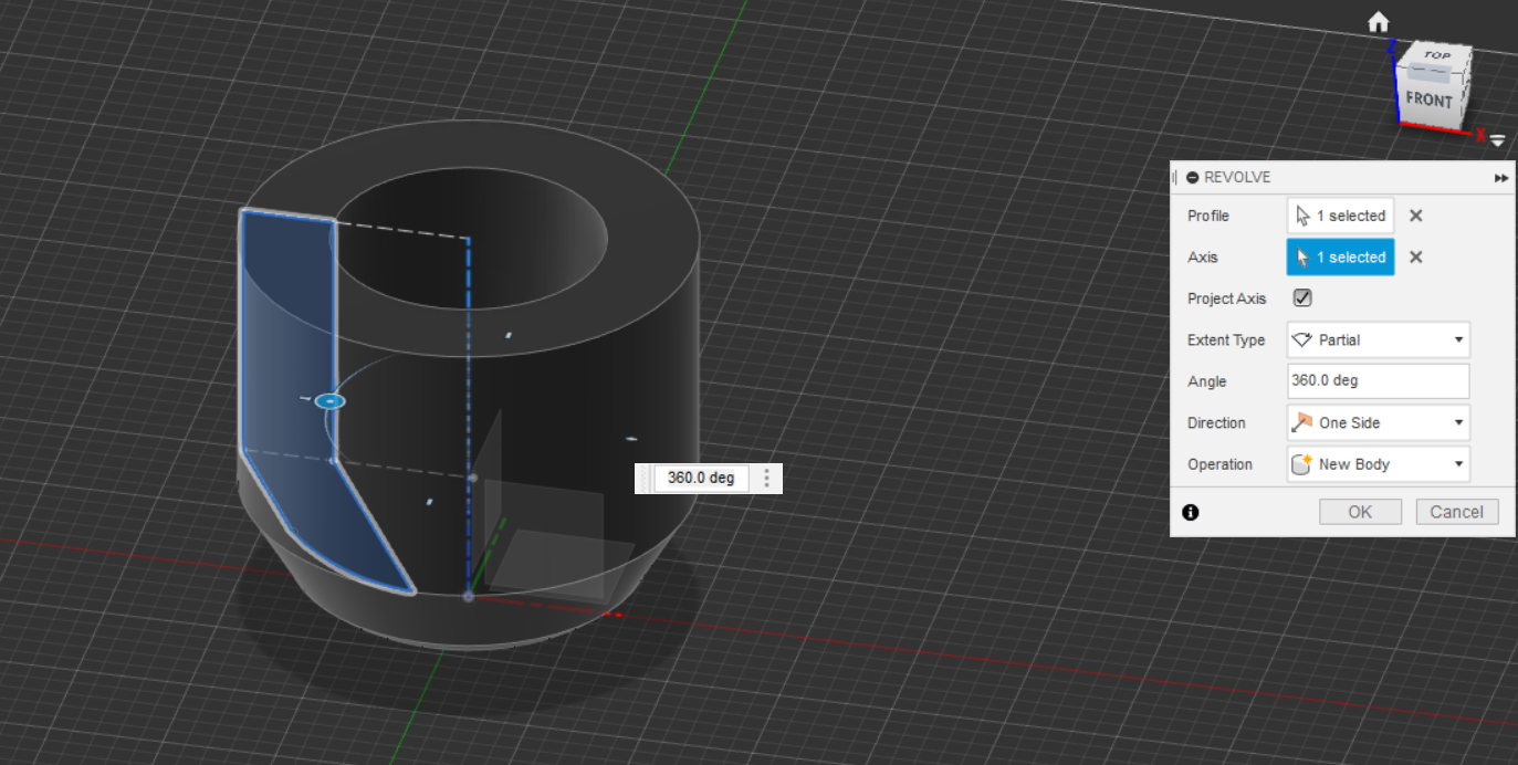
The next operation will be "Revolve", it builds a 3D piece along a construction line by rotating it 360°
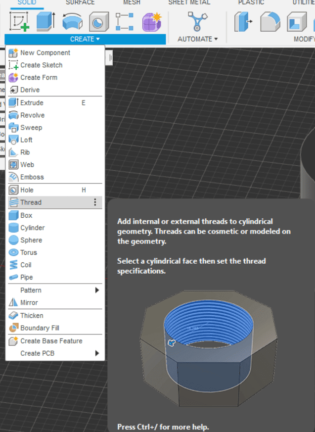
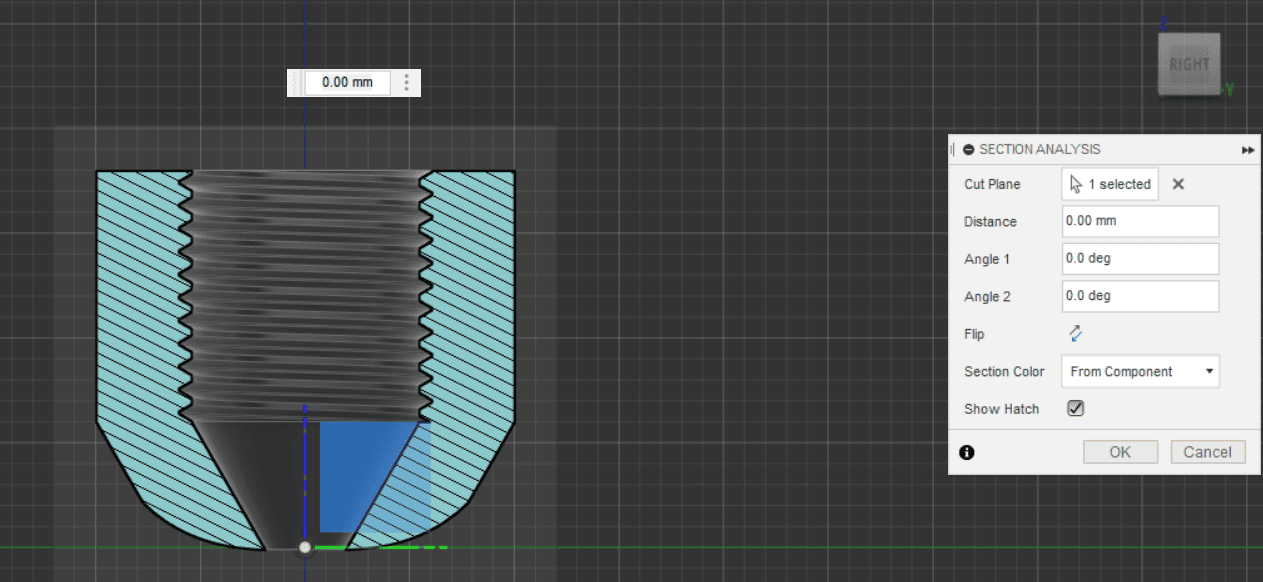
Lastly, let´s add a thread in the middle hole of the piece, we do that with the thread operation, and clicking in the walls of the hole we want to thread.

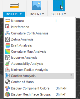
Just to see how it looks inside, we can do a section analysis under the inspect tab
2D Software
Let´s take a look at 2D designing. For this we have a ton of softwares to chose from, this all comes down to personal preference and availability.
- Adobe Illustraitor
- Gimp
- Sketch
- Autocad
- Inkscape
The most popular software in my opinion is Illustrator, but it´s also a paid subscription software, and honestly there are a bunch of alternatives that do the works just as good.
That´s why I´m chosing Inkscape, it´s a free, intuitive software that does vector graphic edition. Download it using this link.

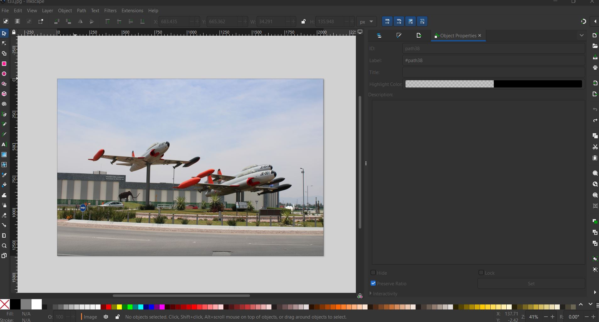
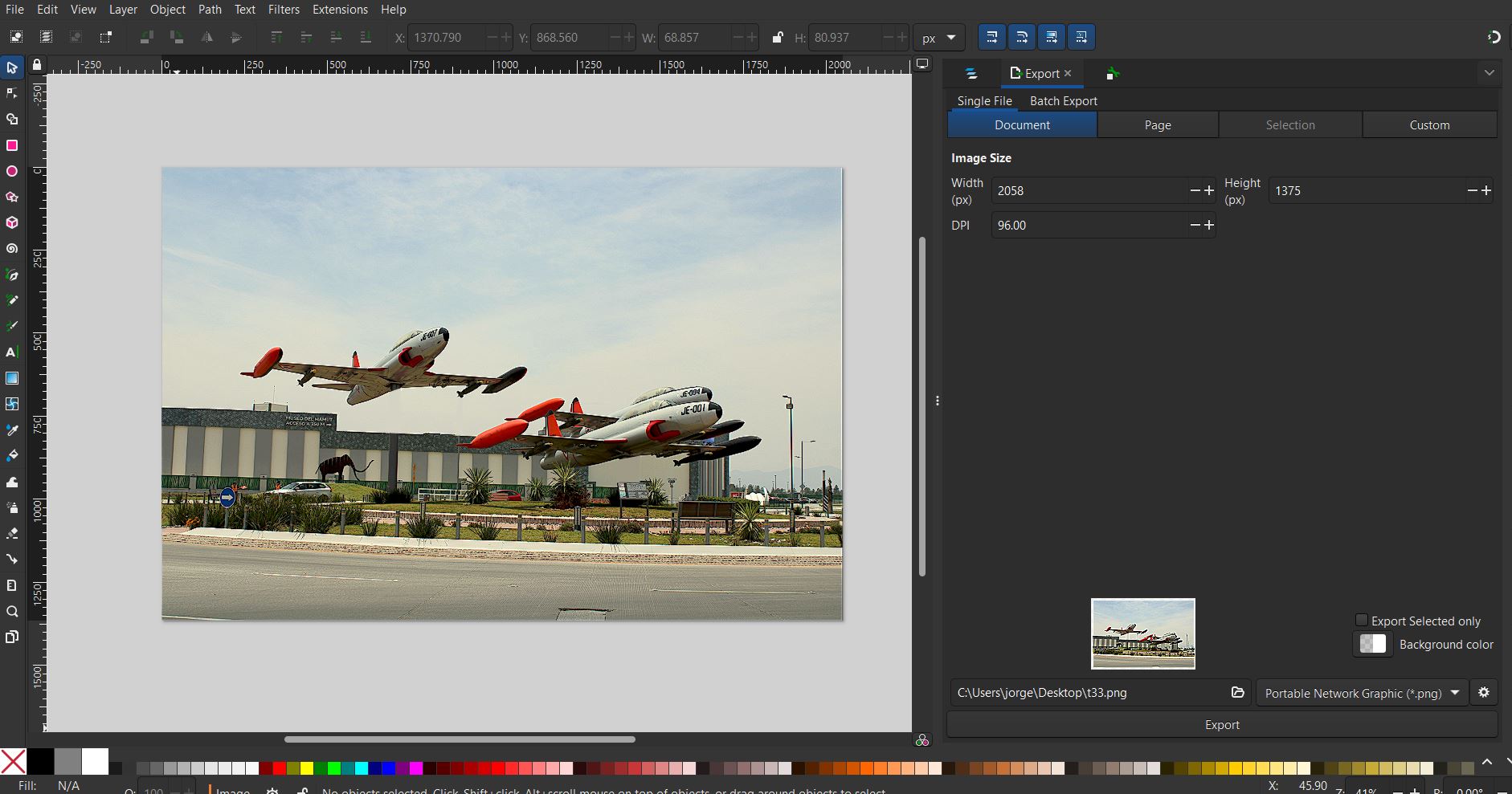
Let´s check some basic tools for this software. What I will be doing is taking a pretaken picture and modifying it using some of the tools available. I will be using this picture I found on the internet, my goal is to make somewhat of a retro postcard

Once inside the software, click on New Document, and open the image on File->Open
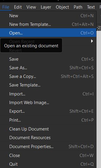
And click open the image you want to work with
First, I´m going to add a filter so it looks more vintage. After thinkering with some of the filters, I selected the old postcard on Filters -> Image Paint and Draw -> Old Postcard.
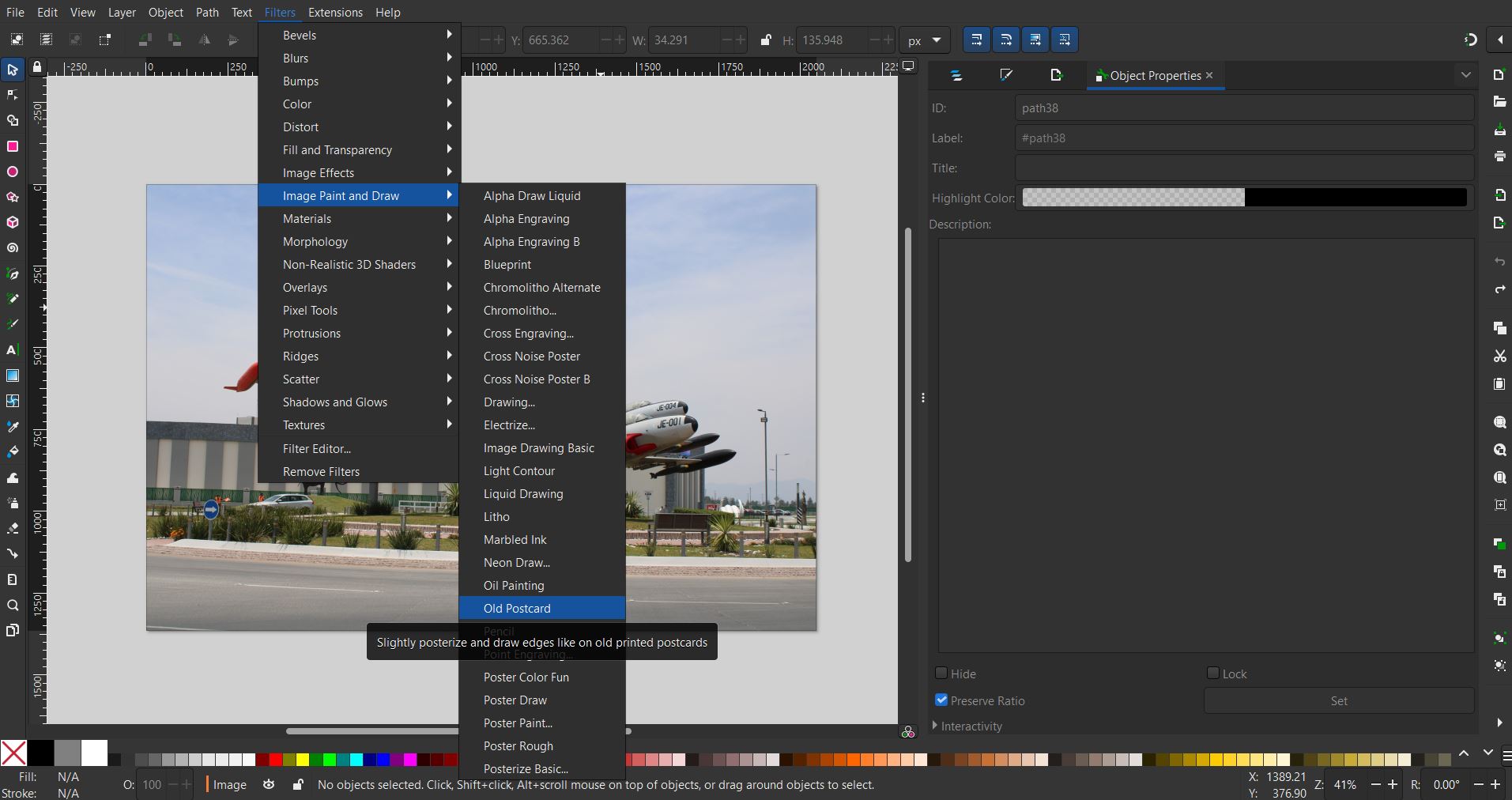
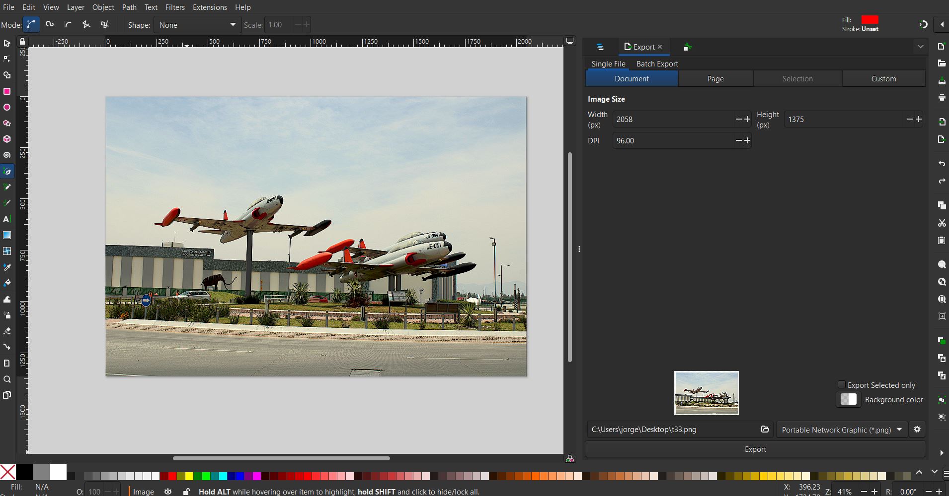
This is how it looks:
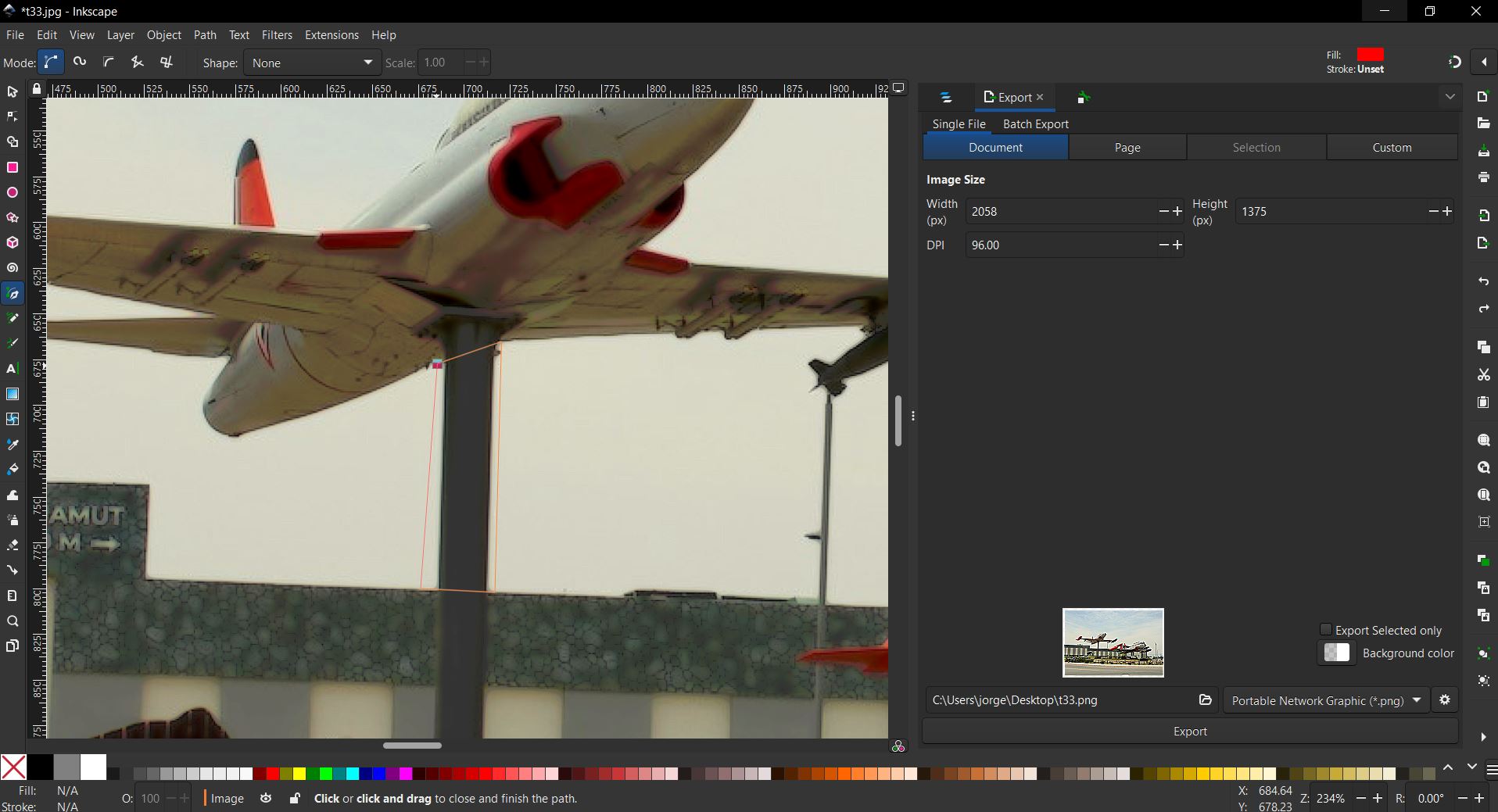
Now, let´s look at the Pen tool, this allows us to draw straight lines to form a shape and put whatever color we want in it. You can find in on the left side menu. To try this, I´m gonna remove the post that´s holding the plane, trying to make it looks like it´s actually flying. We select the area we want to color:

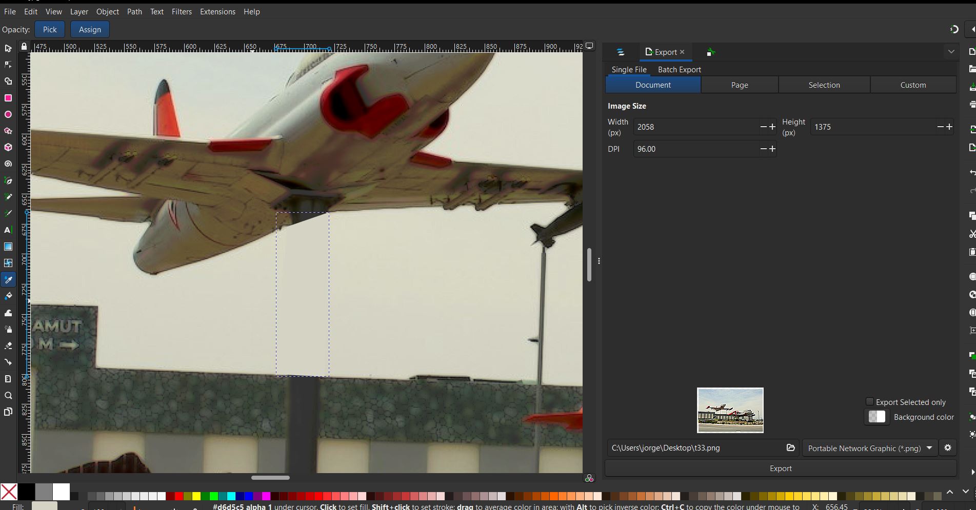
And then, using the Dropper Tool on the left side aswell, select a nearby color to match it.

I did the same on some tubes to the right side, this is how it looks like:
Lets add some text! Again on the left side menu, select the text option and write whatever you please

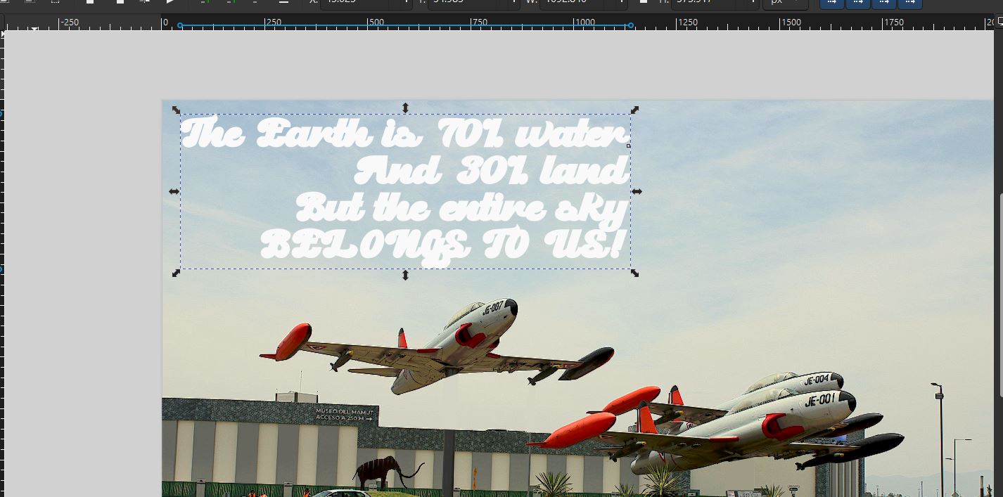
On the top side, you can change the font, size, orientation and more properties of the text.
To make it look better, I adjusted the size of the text, duplicated it, changed color, and overlapped them so it had that retro vibe to it!
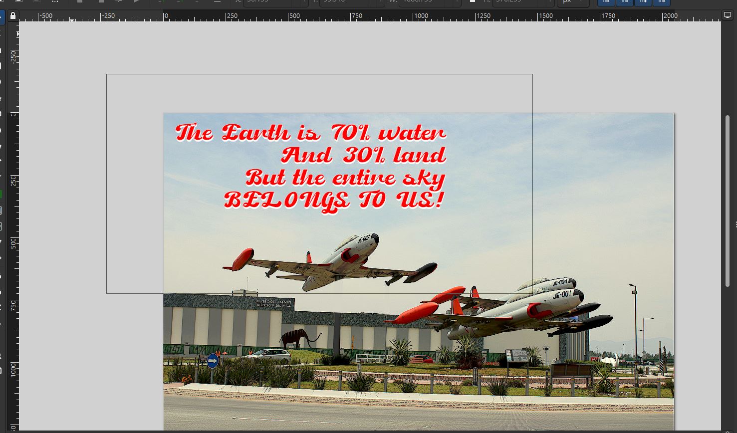
And this is the final look!:

Conclusions:
Working with 2D and 3D software is essential when prototyping, as it lays the foundation for creating accurate and functional models for its later use. Both SolidWorks and Fusion 360 are what I consider to be great starting softwares, offering robust features and have a good potential when mastered. Additionally, learning different 2D software is important for enhancing your design capabilities, enabling you to create detailed plans and technical drawings. Even Photoshop-like softwares like Inkscape, enables you to have multitude of tools at your disposal.