Embedded Networking and Communications
On this week assigment we have to create a communicatio between three different boards.
Communication I2C
There are different types of communication between boards, ISP, UART and I2C. The last one is the one I am going to use beacuse of the microcontrollers I have on my boards.
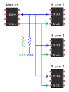
I2C is an acronym for Inter-Integrated Circuit. I2C is a low-speed serial communication protocol used for transferring data. The advantage of using this type of communication is that you only need two wires to make the communiation between all the devices.
 Master and slave devices
With this type of communication networks consist in a master device and a slave device.
The master device is the one how sends and recieves data. Slave devices respond to the data that the master sents them.
The slave devices are the ones that recieves the data, each slave must have and I2C addres in order to identify the device and make it possible to the master device to send data to an specific slave device.
Coding
The plan is to used the board I made on week 4, wich has an attiny 45 as microcontroller, as the master and the board I desgin on week 8 and an Arduino Uno as slaves. The Arduino Uno will have connected a servomotor that will be controlled using two buttons placed on the Attiny 45 board and two leds that are on the rp2040 board will be used as indicatiors when you reach the max and min angle of the servo.
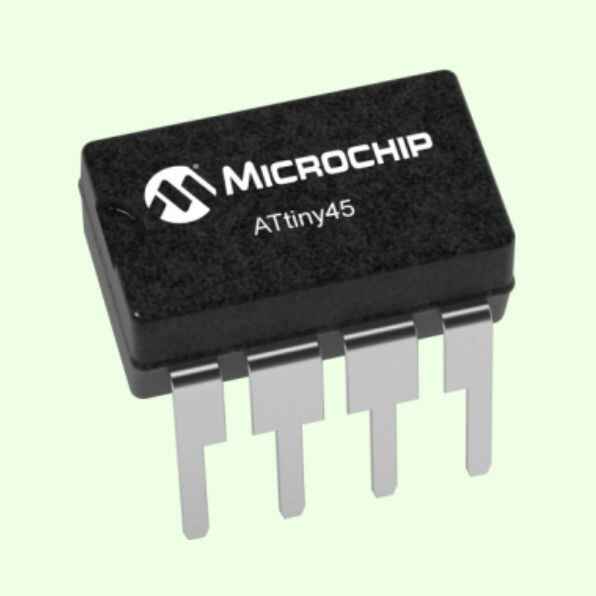
Attiny 45 (MASTER)
		#include < Wire.h >

		void setup() {
			// put your setup code here, to run once:
			Wire.begin();
			pinMode(3, INPUT); // Enable button 1
			pinMode(4, INPUT); // Enable button 2
		}

		void loop() {
			if(digitalRead(3) == HIGH){
				Wire.beginTransmission(8); // Send to Xia to turn LED indicator
				Wire.write(1);
				Wire.endTransmission();

				Wire.beginTransmission(9);
				Wire.write(1);
				Wire.endTransmission();
			}
			else if(digitalRead(4) == HIGH){
				Wire.beginTransmission(8); // Send to Xia to turn the other LED indicator
				Wire.write(2);
				Wire.endTransmission();

				Wire.beginTransmission(9);
				Wire.write(2);
				Wire.endTransmission();
			}
			else{
				Wire.beginTransmission(8); // Send to Xia to turn LED indicator
				Wire.write(0);
				Wire.endTransmission();

				Wire.beginTransmission(9);
				Wire.write(0);
				Wire.endTransmission();
			}
			delay(100);
		}
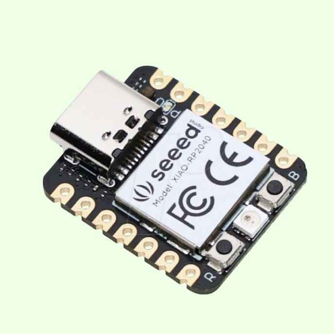
Xiao RP2040
With the rp2040 I wanted to use two of the leds that I already have on the board and use them as indicators.
		#include < Wire.h >	//Include Wire library (I2C communiation)

		void setup(){
			Wire.begin(8);
			Wire.onReceive(receiveEvent); //Recieve the data from the Attiny
			pinMode(D6,OUTPUT); //Enable LED 1
			pinMode(D7, OUTPUT); //Enable LED 2
			Serial.begin(9600);
		}

		void loop() {
			//Nothing on loop
		}

		void receiveEvent(int howMany){ //When data is recieved
			while(Wire.available()){
				int led = Wire.read(); //Set data as led

				if(led == 1){
					digitalWrite(D6, HIGH);
					Serial.println("Led 1 turned on");
				}
				else if (led == 2){
					digitalWrite(D7, HIGH);
					Serial.println("Led 2 turned on");
				}
				else if(led == 0  ){
					digitalWrite(D6, LOW);
					digitalWrite(D7, LOW);
					Serial.println("No led turned");
				}
			}
		}
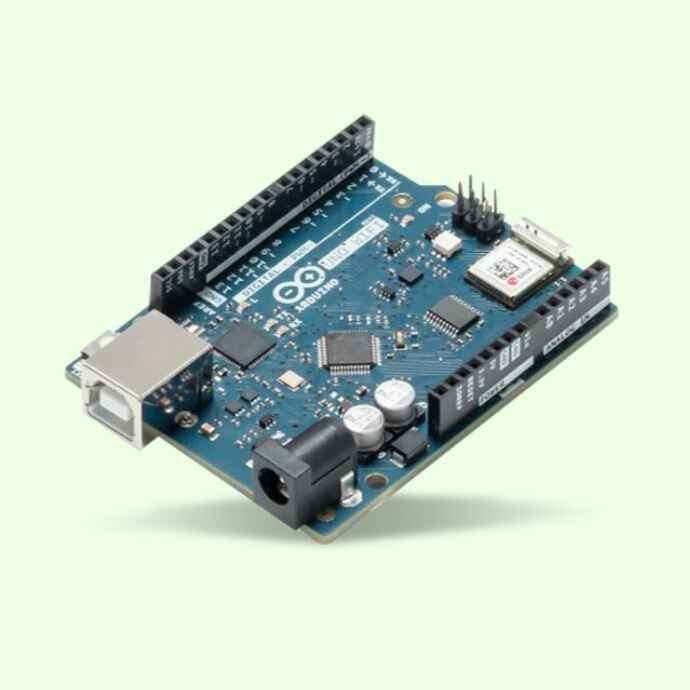
Arduino uno
The Arduino Uno will also recieve wich button from the master board is being pressed and it will move a servomotor one direction or other. Also it will print the how the servo is moving, left or right.
		#include < Wire.h >
		#include < Servo.h >


		Servo servoMotor;

		int s = 45; //inicial angle of the servo

		void setup() {
			Serial.begin(9600);
			Wire.begin(9);
			Wire.onReceive(receiveEvent);
			servoMotor.attach(5);
			servoMotor.write(s);
			Serial.println("Hi :D");
		}

		void loop() {
			//Nothing on loop
		}

		void receiveEvent(int howMany){ //When data is recieved
			while(Wire.available()){
				int x = Wire.read(); //Set data as x

				if(x == 1 && s <= 90 ){ if the angle is lower than 90° add 5°
				s=s+5;
				Serial.println("Left");
				}
				else if (x == 2 && s >= 0){  if the angle is higher than 0° subtract 5°
					s=s-5;
					Serial.println("Right");
				}
				else if(x == 0){ else stay the same angle
					s=s;
					Serial.println("Nothing");
				}
			}
			servoMotor.write(s);
		}
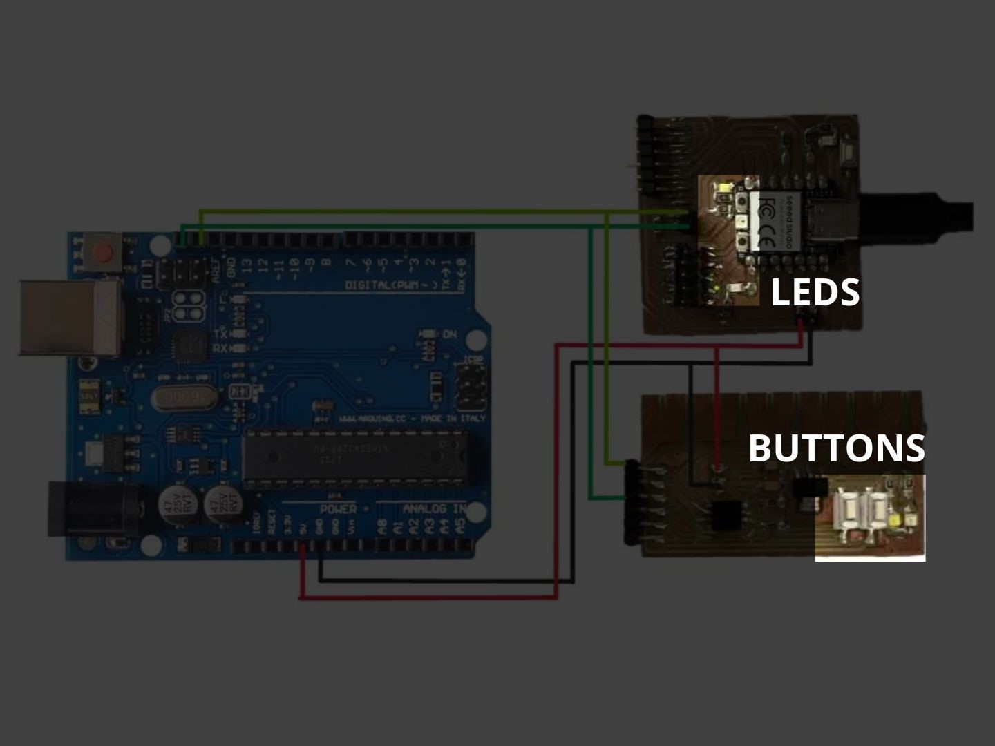
Schematics
Here is how I connected the three boards with each other to make the I2C communiation.
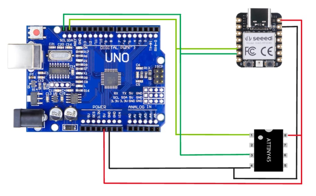
Ass you can see, the leds an buttons are alrady integrated on the pcb, the only thing that I have to connect was the servomotor to the Arduino UNO.
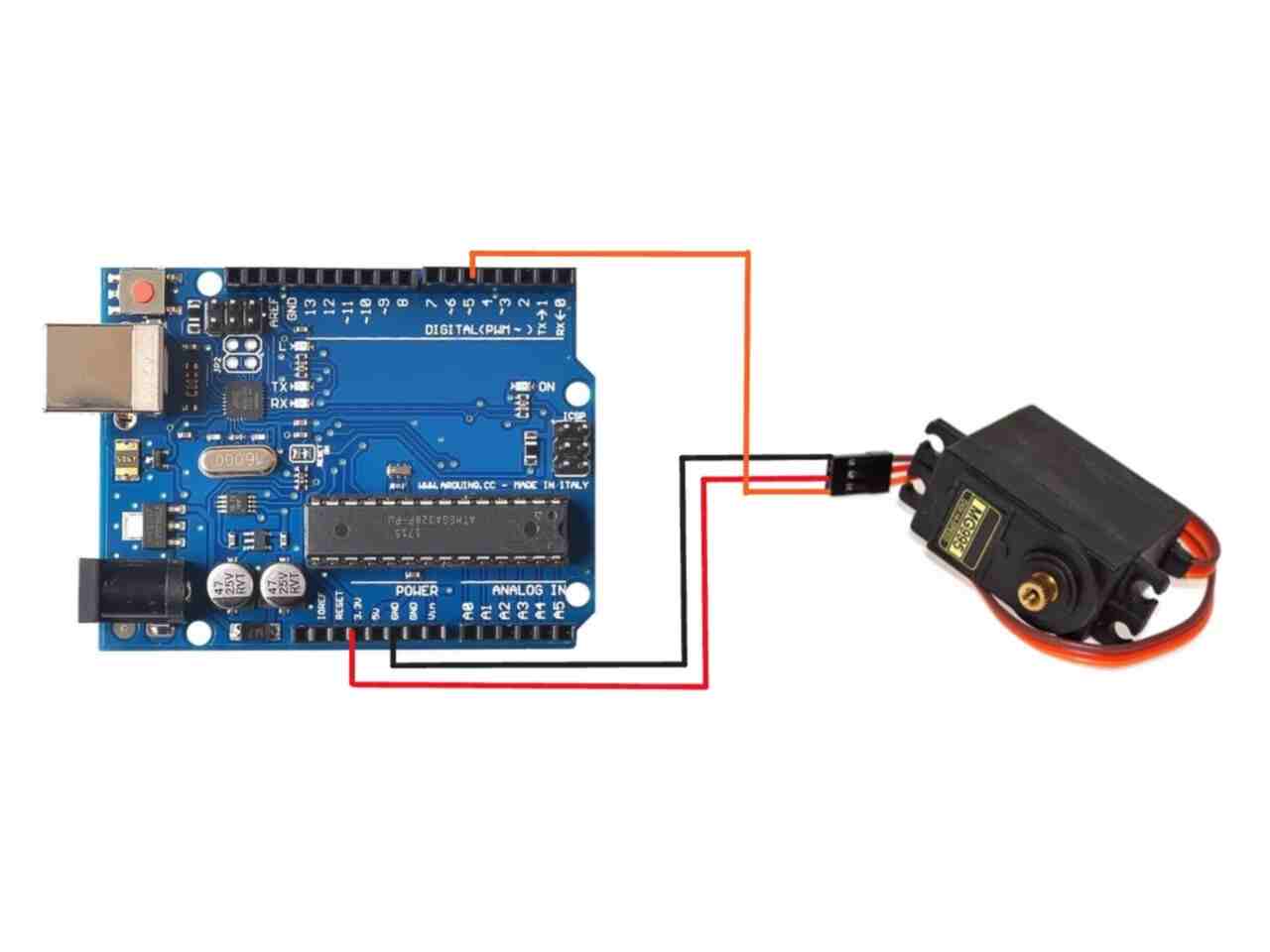
Here is how I connected the servo to the Arduino.
Result
Here is the result of all the codes working together and communicating with each other. The sermotor I used is from one of my previous college projects.