Electronics Production
In this week assignment we will learned about PCB production process by creating a microcontroller.
PCB production process
Tool-path
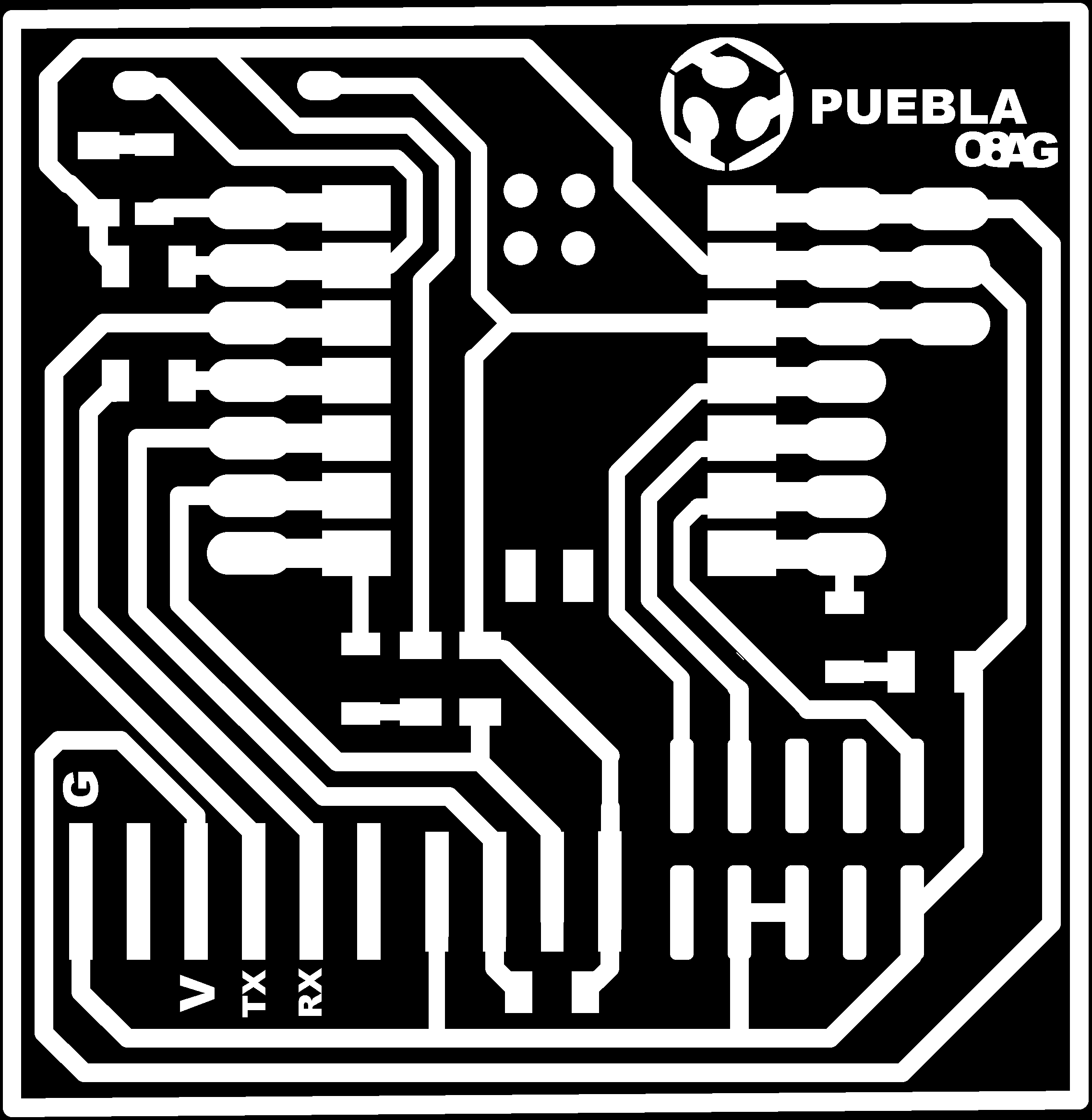
First of all, I had to create the Tool-path. The machine I will works with .rml files so using MODS' website that we learned to used on our group assignment I will convert the images of the PCB that our professors gave us into .rml files.

To turn the images into .rml files we have to make the following steps on the website:
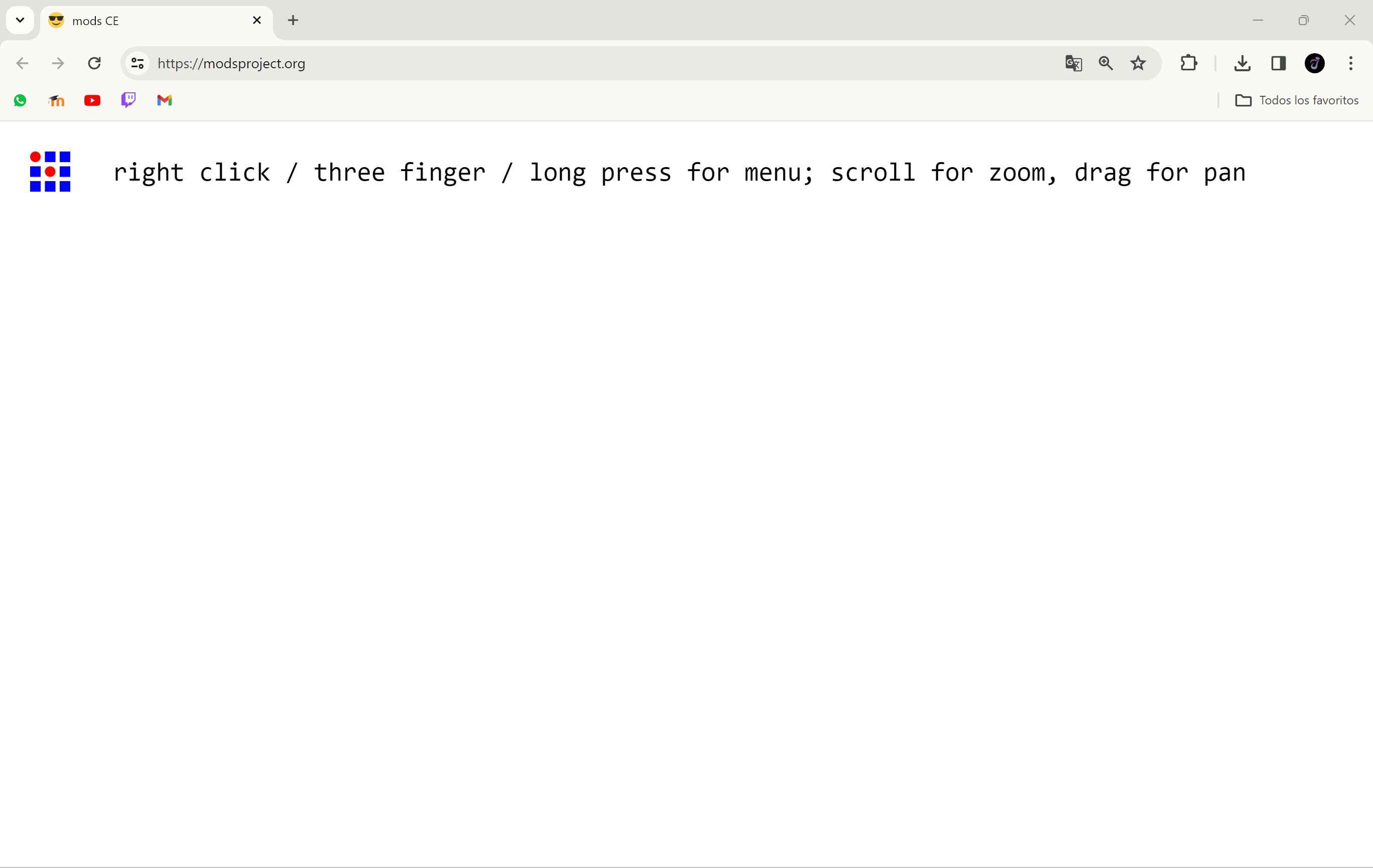
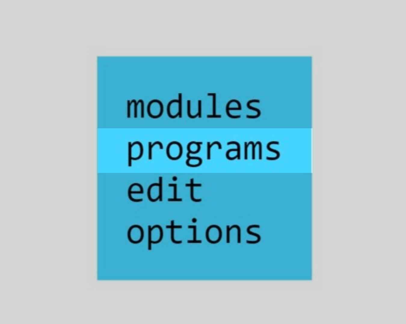
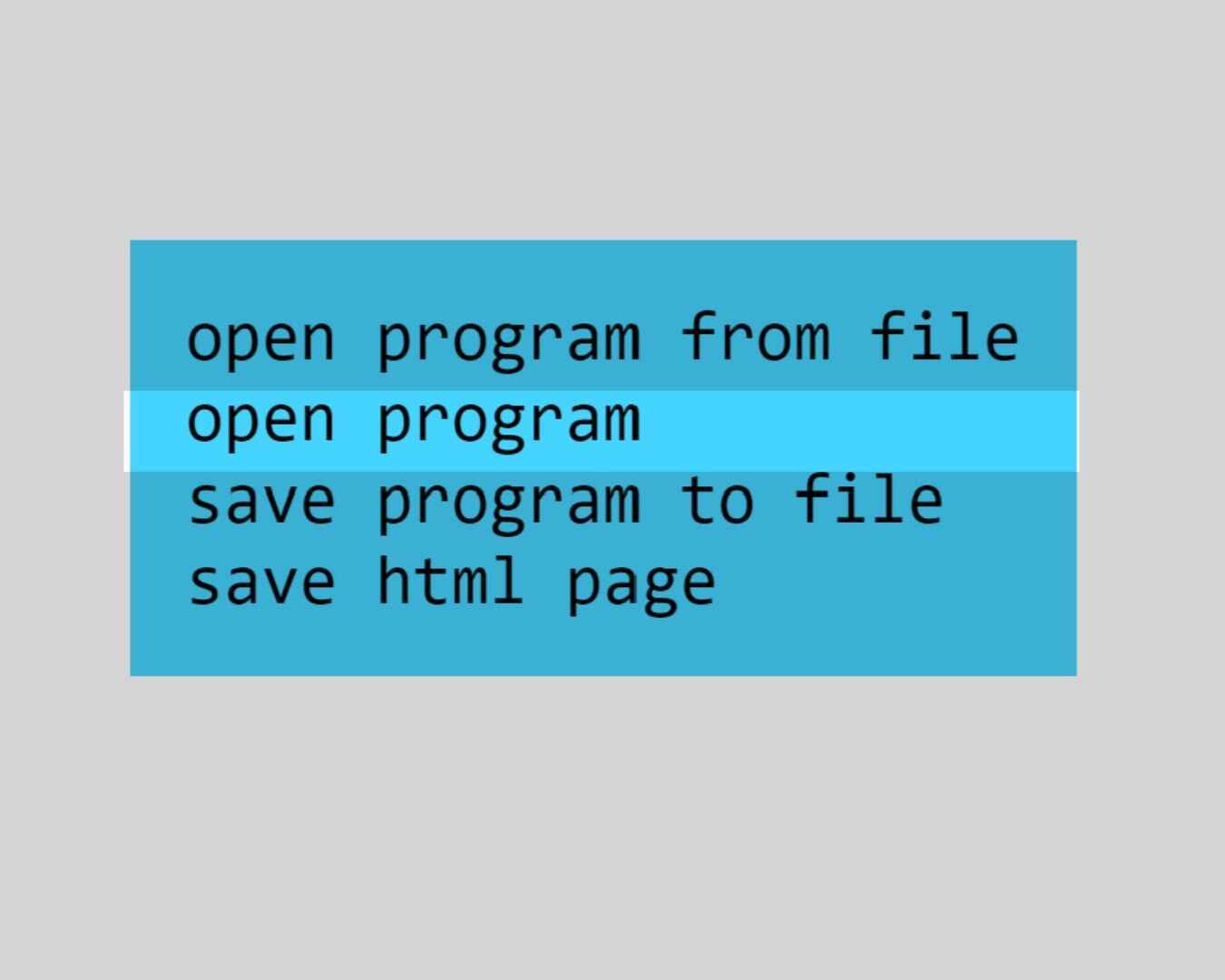
If you followed those steps you will end up with your webpage looking like this.
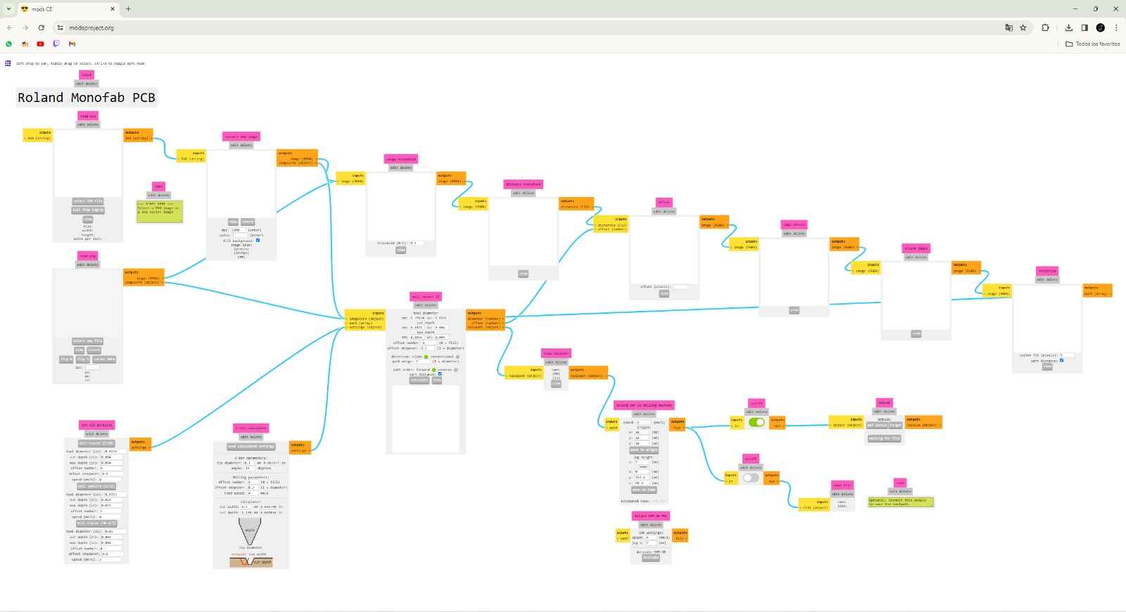
In here you have to modify certain "blocks" and values depending on what you want to do.
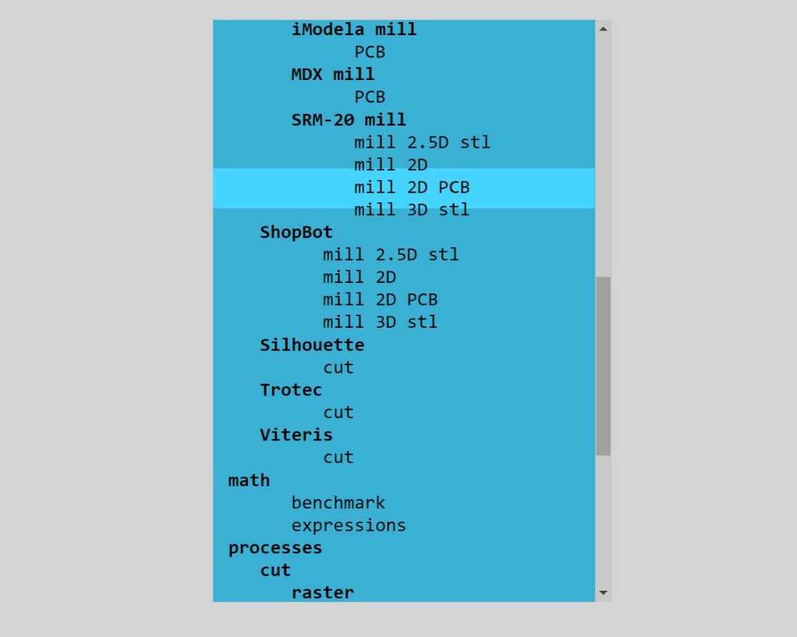
PCB settings
In here you will select what type of mill you want to make.V-bit calculator
It calculates the V-bit and milling parameters (in my case it stay the same)Mill raster 2D
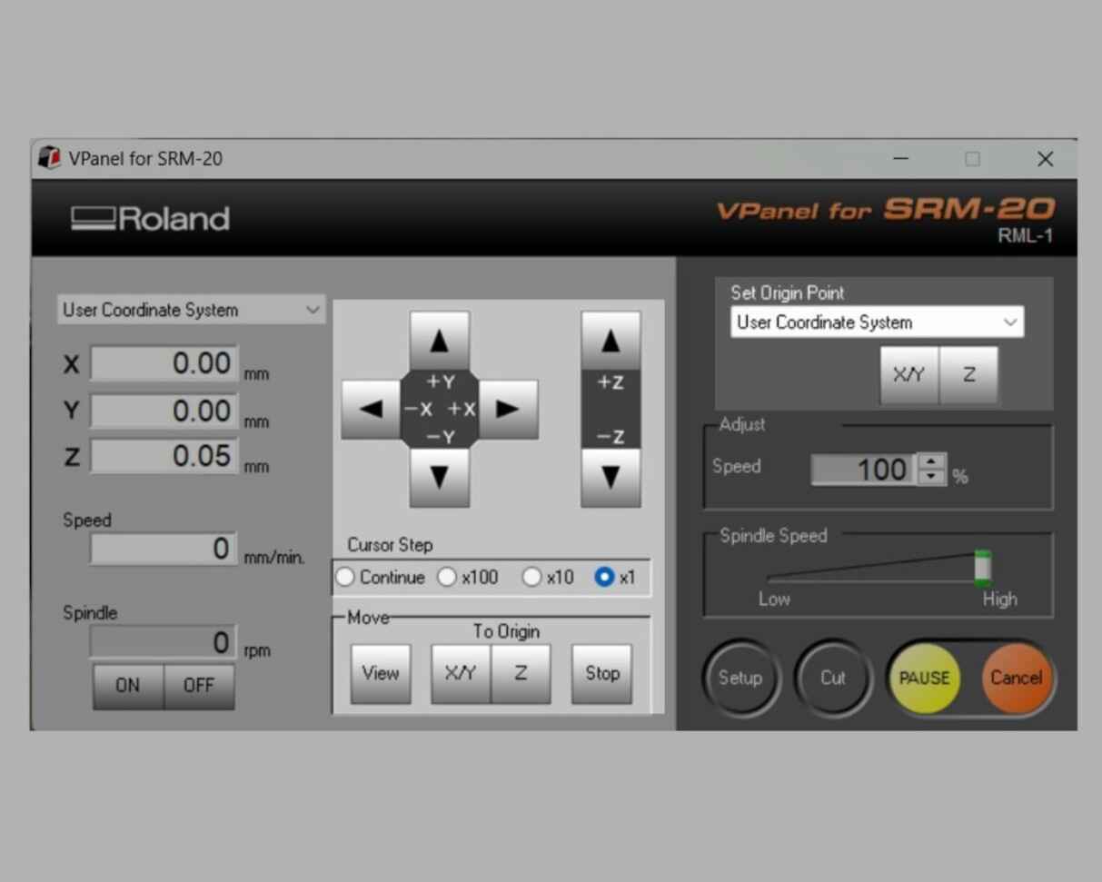
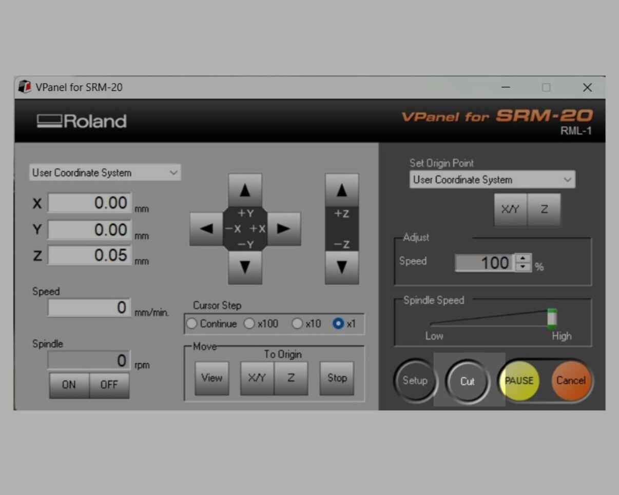
It creates the trace of the of the image (I change the offset number to 2).Roland SRM-20
It sets the speed and the origin (I modified the origin to 0).
Lastly, we have to check if these buttons are "on"
Once I set al the cinfiguration, on the "Mill raster 2D" block, I clicked on the "calculate" button and it downloaded the .rml file for the engraving. Now I have to repeat the process but changing a few parameter to get the outline. The modified parameters were:
- Invert the image beacuse I want the black line to be cut.
- Milled outline 1/32
- Offset number on 1
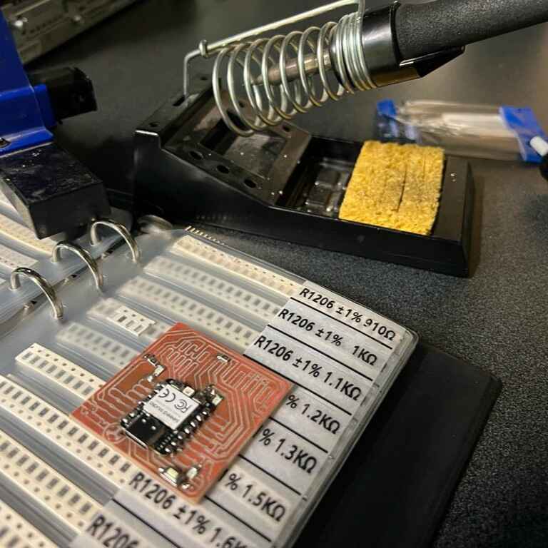
Milling
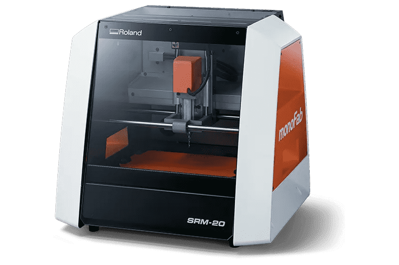
There are three different models of Mini-Mill at FabLab Puebla. These tools operate by translating digital designs into physical circuit boards. The model I used was the Roland SRM-20 cause of his high precision as PCB milling.
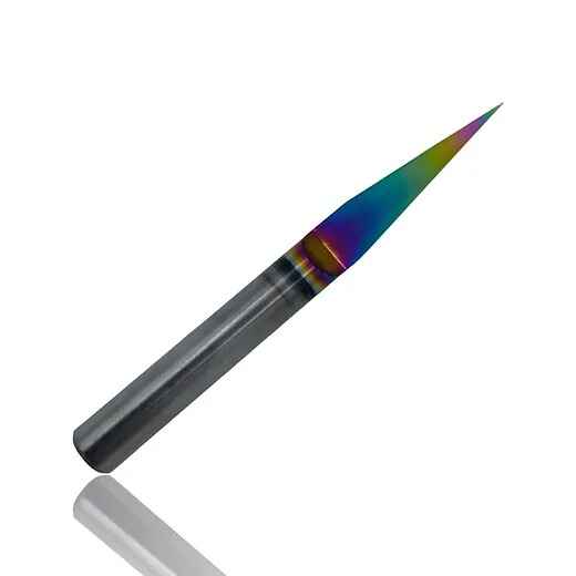
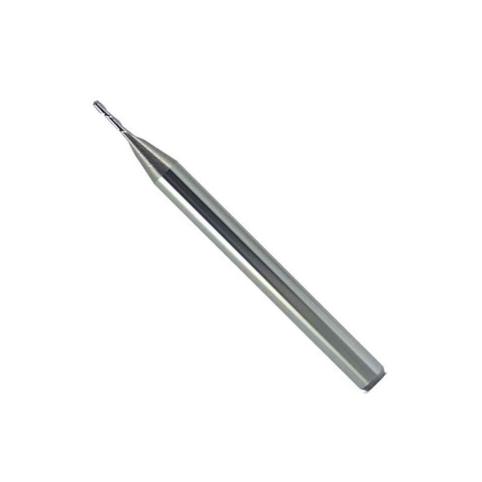
I used two different tools, a 15 degree V-bit for engraving and a 0.8 mm diameter two flute end Mill for cutting.
Before we start using the machine we had to gut our "sacrifice bed" and double-sided tape to place the copper sheet on it. "
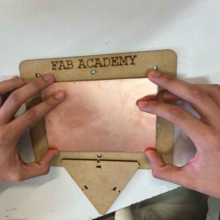
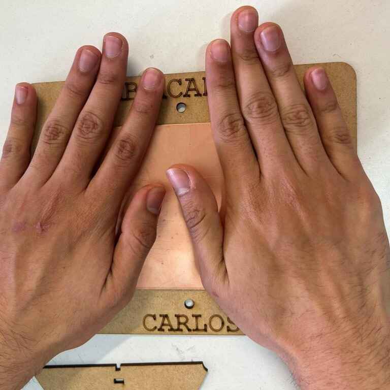
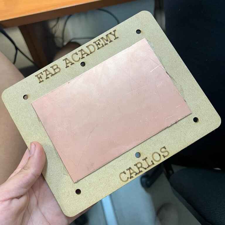
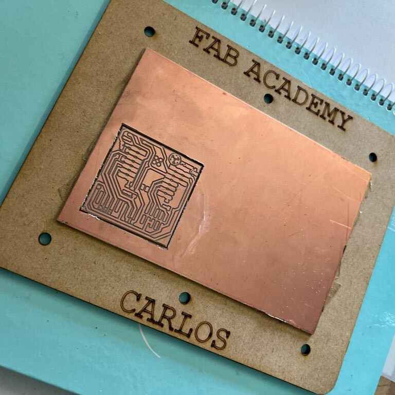
Now, it was time to use the machine:
Heres is the result:
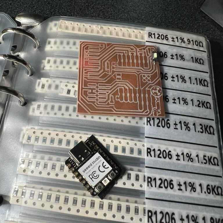
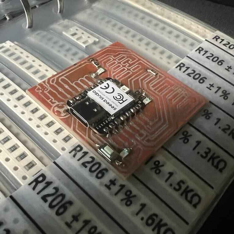
Stuffing and soldering
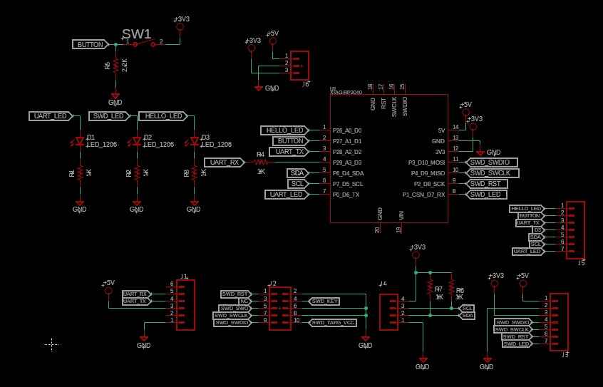
Now that the milled board was ready, it was time to solder the componnets. Our professors gave us the schematic, on it we can identify all the components we needed.
| Material | Quiantity |
|---|---|
| XIAO RP2040 | 1 |
| Push button | 1 |
| 2.2K Reistor | 1 |
| 1k Reisitor | 5 |
| LEDs SMD | 3 |
| Pin headers | 16 |
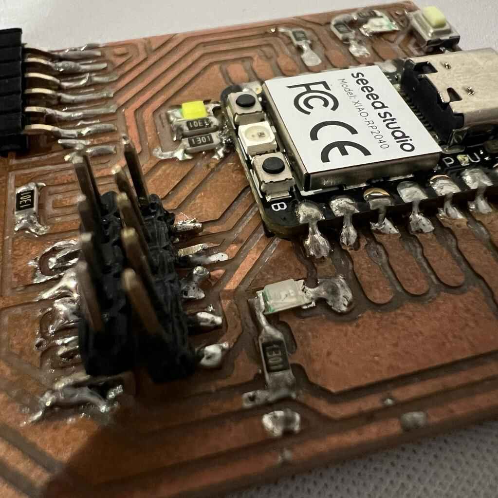
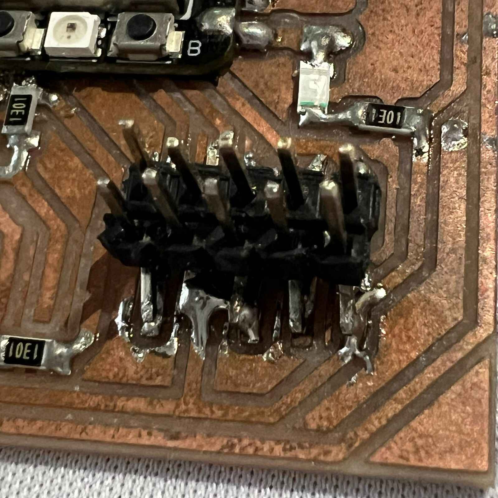
Before start soldering I had to tape the bottom of the microcontroller so the copper plate can not touch the connections underneath the XIAO. It was my firt time soldering tiny components, and I was pretty nervious. For some reason, the last 10 pin headers were difficult for me to solder and I ended up making a mess, something I fixed using a desolder pump.
Testing
Once everything was soldered it was time to test it.
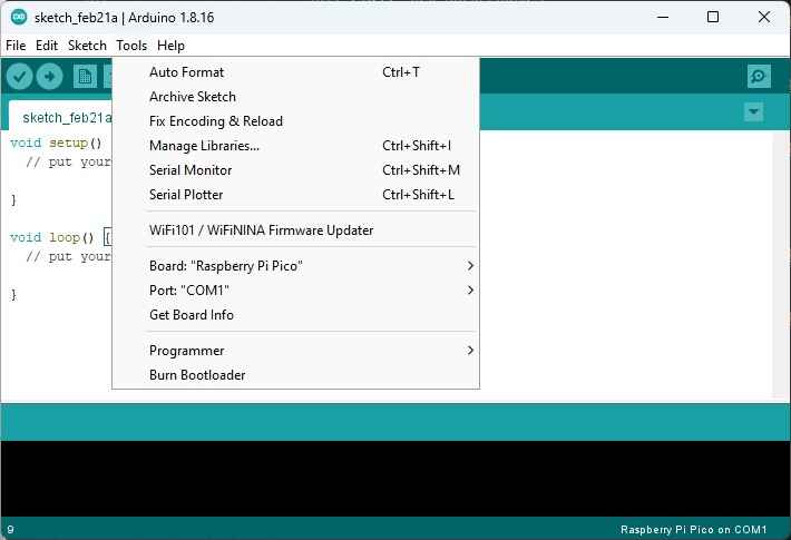
Here is the code that our professor Huber gave us, it purpose is to make the 2 LEDs blink and turned the other LED on when the button is pushed.
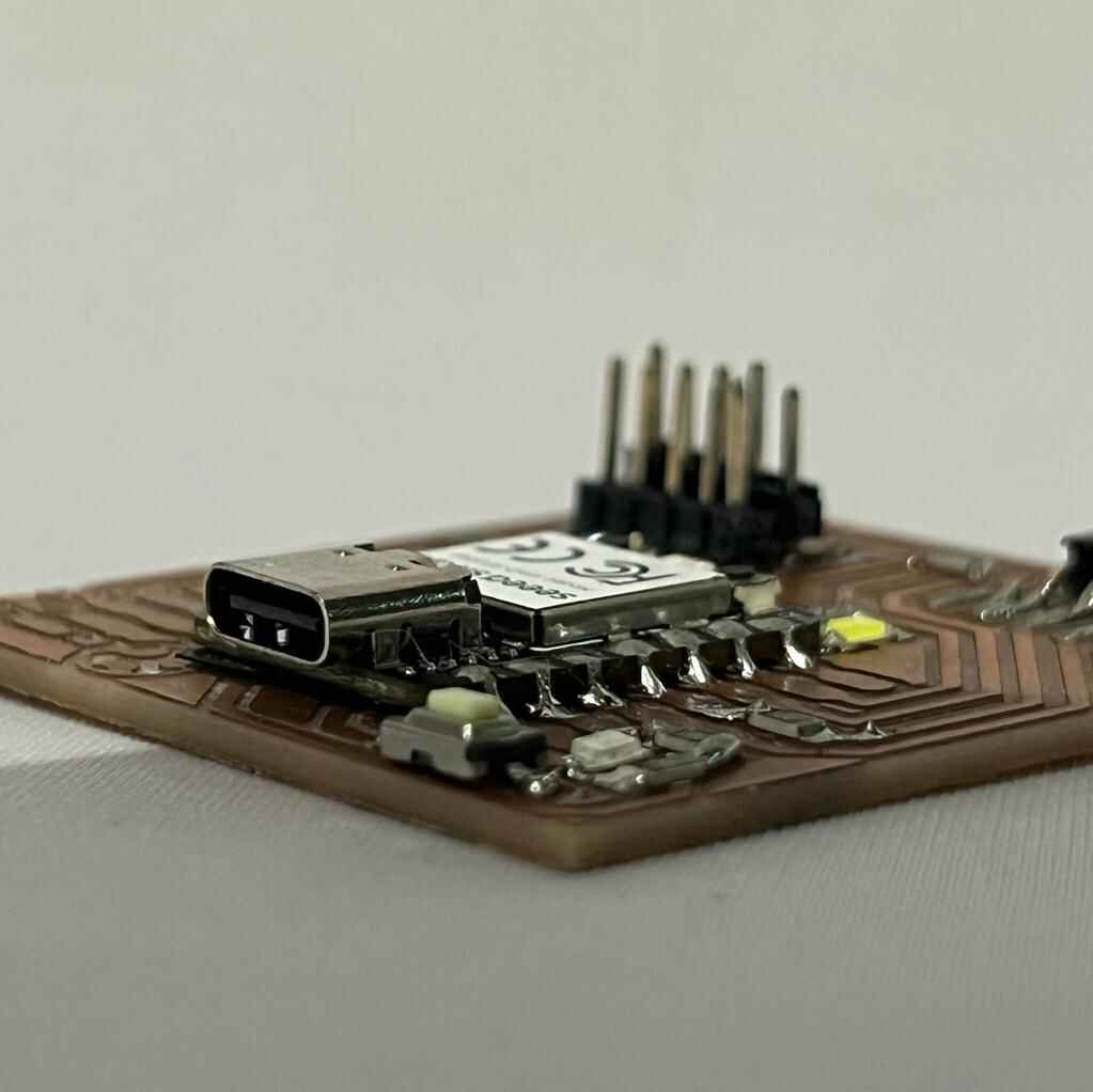
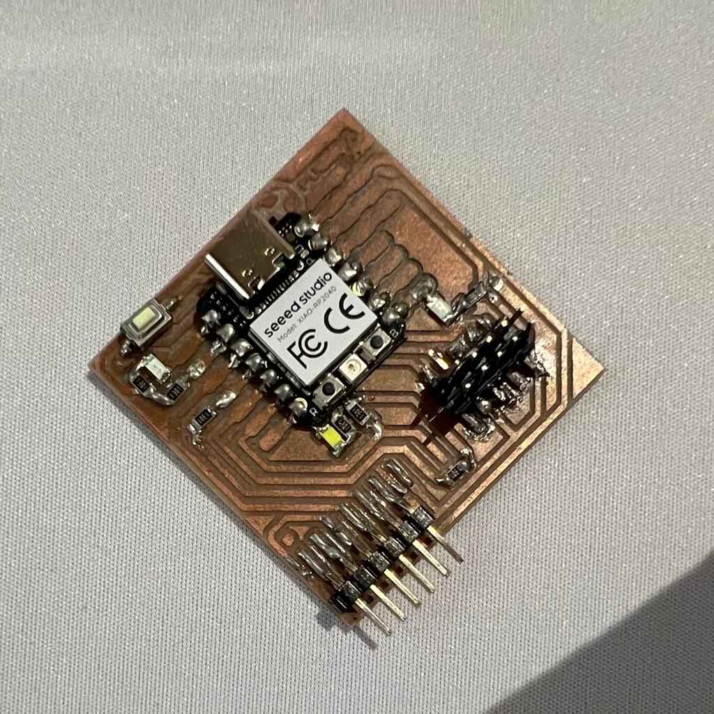
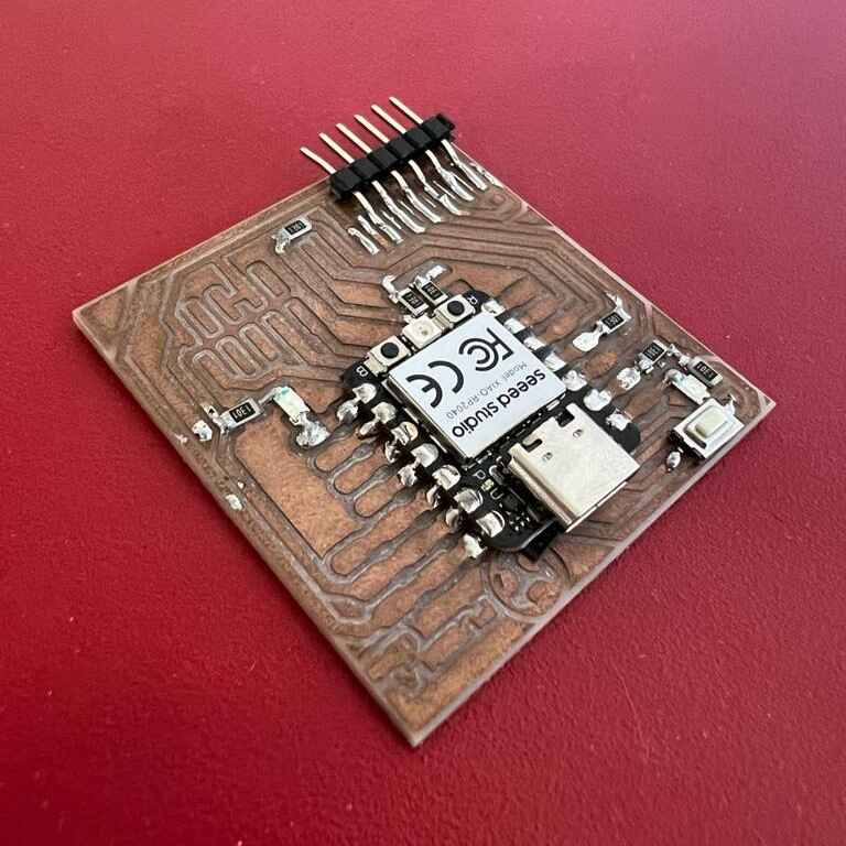
Final result
Now that we tested it was time to make a photoshoot.