16. System Integration
On this week I will explain some key aspects of my final project. I will explain how all the components works together and why it will work my project. My project will be divided on 3 parts. The first one is the mechanic part, all the 3D parts and motors. The second part is the electronic part, the battery, the PCBs and also the motors. Finally, the last part is the interface part.
Mechanic Part
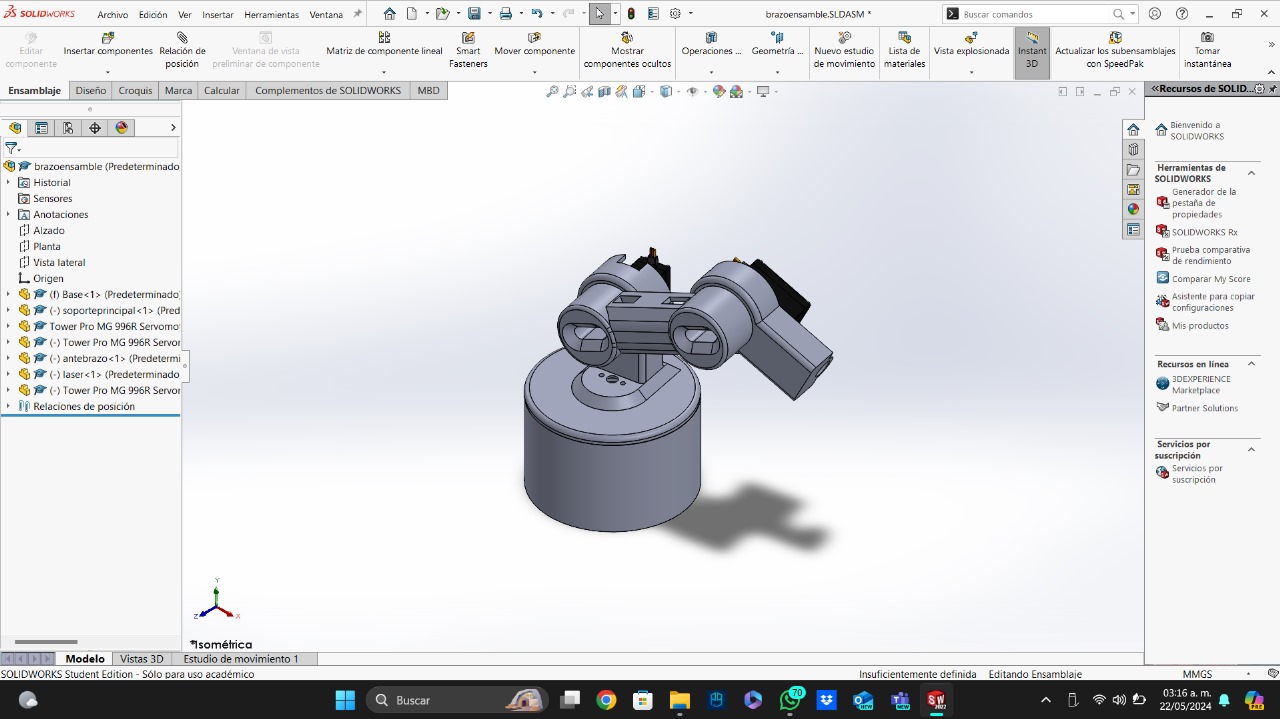
For the mechanic part, I based my parts in some ideas I found on internet. I specially based my designs on this video. To be honest, the designs aren't difficult. I was worried about the wires management, but I left some holes and channels for hiding the wires. I also made the my project's base thinking in having all the wires inside.
Testing
To be honest, the only thing I tested, was the assembly on SolidWorks. I made the assembly with all the pieces, including the servomotors, and checked the movement. I also think in the 3D printers tolerances in order to don't have any trouble with fitting the components. I also included sections to hold the battery and the PCBs.
Maintenance
I think it won't be necessary. The PLA is a strong material that only breaks when you apply a considerable amount of force on it.
Electronic Part
First, all my system will be controlled using a SEEED XIAO ESP32S3, because I am interested in using the camera of this board. Like I said before, I designed the parts with some wires channels and other holes. On this part, I was concerned about the amperage used by the three servomotors, this problem is due to the maximum amperage that the XIAO can deliver at its 5 volt output, since the 3 servomotors may need more amperage than provided and could burn the XIAO. To solve this, I got an adjustable power supply, which delivers a maximum of 5 amps and 5 volts, more than enough quantities to control the servomotors.
Testing
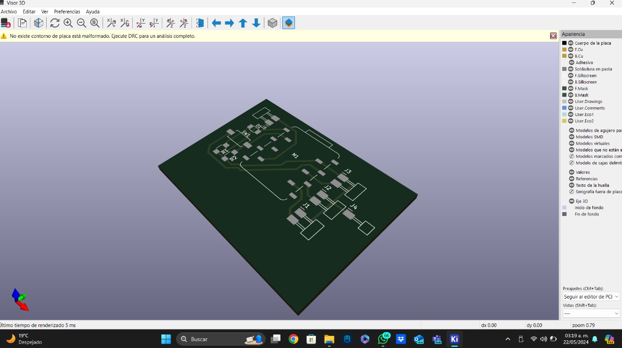
First, I made sure the schematic of my PCBs was right. I checked them with my professor and after milling the PCBs, I checked all the paths to make sure everything was milled right. I fixed some paths and checked continuity. The PCB has a button and a LED to checked the PCB in a simple way. After soldering, I tested the PCB uploading a code to the XIAO ESP32S3. If something didn't work, I checked continuity until I find the problem to solve it. I will be using the servomotors MG995 to hold all the robotic arm pieces. Finally, I tested the laser using one of the digital outputs of the ESP32S3.
Maintenance
The maintenance is just making sure all the solders are right in order to avoid short circuits or long term malfunctions.
Code
The difficult part of the code is the serial communication with the interface.A lthough this is the hard part, the interface is only going to have buttons, so the arduino code will consist of different conditionals for each component that will move the servos to point to the desired component.
Interface Part
The interface is a kinda complex. First, it will have a sign in screen where you should write your Ibero's id, this is in order to know who takes what component. The second part is where you can select the components and the quantities of each one. The idea is to send this information to a data base that my coordinator will have.
Testing
I don't really need a big testing part, but I will design the different screens and learn how to link the interface to a data base and how to send the interface data to this data base. Finally, I will solve the serial comminication with the XIAO ESP32S3 making the codes requiered to send which component button is pressed.
Maintenance
It isn't needed on this part, I just need a charged laptop and to keep connected the XIAO ESP32S3 to this laptop. For testing purpouses I will be using my laptop.
Code
Like I said befire, I will make the code needed to send which button is pressed. This information will be requiered on the Arduino code uploaded to the XIAO ESP32S3.