3. Computer-controlled Cutting
On this week I worked on learning to use the laser cutter machine and its program to create a parametric assembly kit. I also learnt to cut a vinyl sticker for my phone.
Learning the equipment
Before cutting and designing my kit, I took the introductory course to learn how to use the laser cutting machine. I also took it to learn about the kerf and the tolerances neeeded to got a succeed cut, the tolerances I used to compensate the lost material (kerf) were of 0.2mm. These are the steps to be succesful at laser cutting:
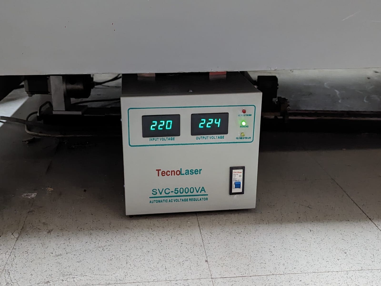
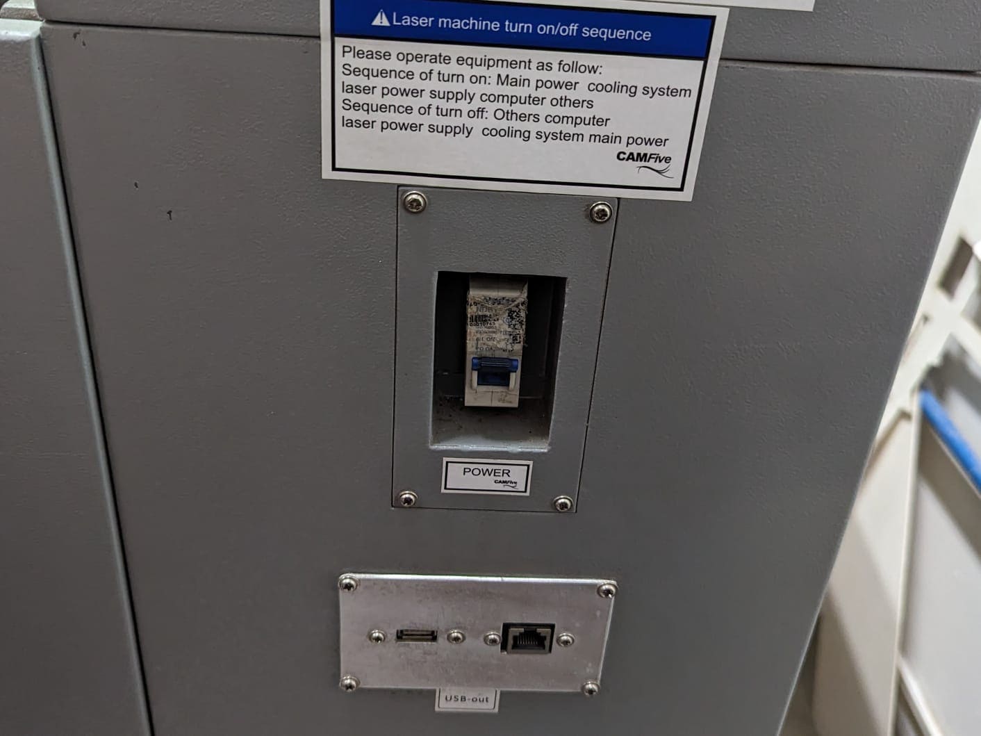
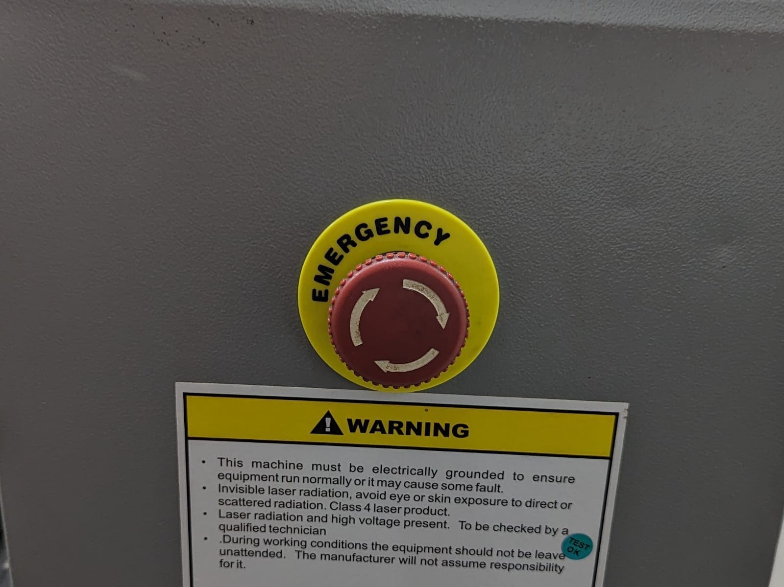
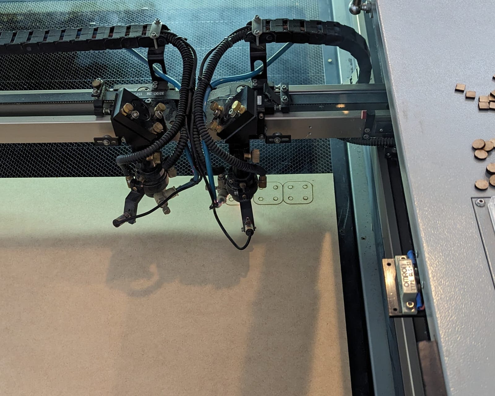
- The Basics: To start using the laser cutting machine, we first neeed to turn on the laser cutting machine. This is a very simple process that consits in turning on the regulator and power, and then, turning off the emergency button.
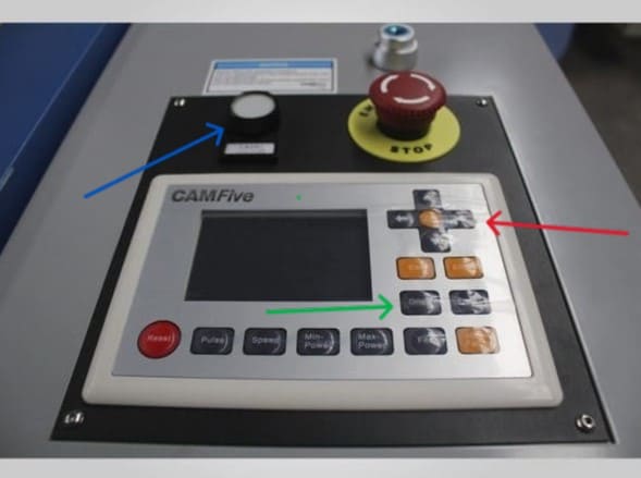
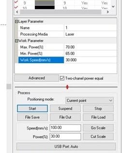
- The Control Panel: It is very important to learn how the laser cutting machine panel works. Basically, we have the D-pad to move the laser on the X and Y axles (red arrow), to move on the Z axis, we first need to push the center button of the D-pad. To set the origin on your cutting material, we have the "Origin" button (green arrow), and to turn on the laser, we have the white button (blue arrow) and knob above to change the intensity.
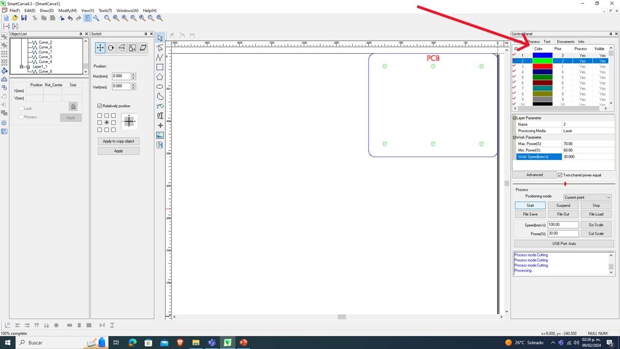
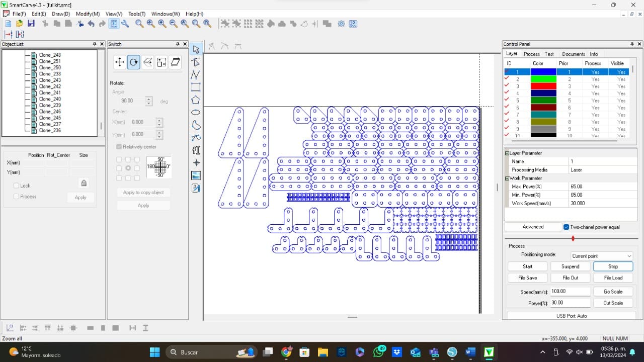
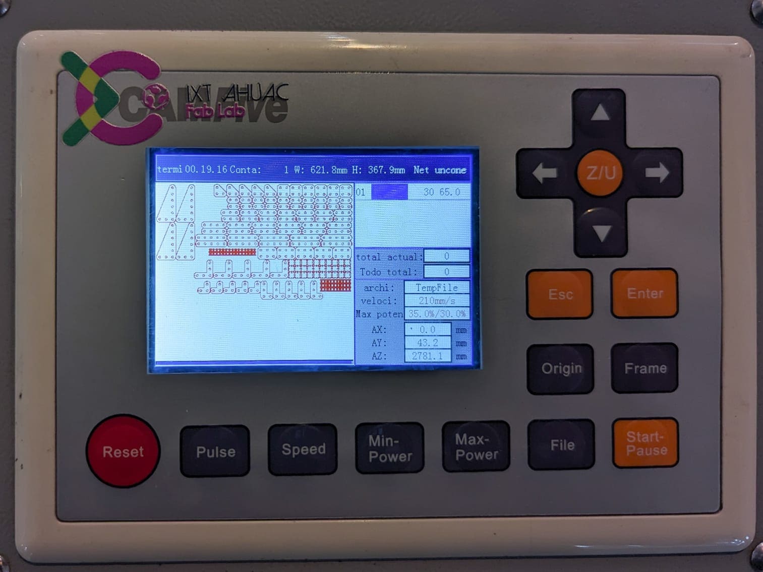
- The Software: Now that the machine is working, it is time to start using the software to import our dxf files and start cutting. The software is simple to understand, it works using different colors in which every color can have a different power percentage and a different work speed, the colors are also used to have a priority order.
- Interesting Features: The software I am using for this week has a several of useful functions. One of them is the "Go Scale" button, this button activates the laser cutting machine showing the space requiered to make an effective cut. We have some other features like the multiplier button, the double line eraser, the route optimizer, and many others. To start the cut, we just need to press the "Start" button that is below the color panel.
- Before Cutting: Before you press the "Start" button, you should check that the laser origin and your program origin are the same, because this can cause a wrong cutting, or maybe not even a cutting.
Parametric Design
To create my assembly kit, I based my ideas on an old 3D model that I used to learn the Assembly module in Catia. This old model was created using a toy model of a plane that had different screws, so I changed and adapted the pieces to the laser cutting world.
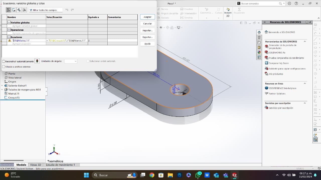
Before I started designing, I needed to learn how to create a parametric model. To find out how to create the parametric model, I watched this video. To summarize the video, the parametric model works using the SolidWorks' ecuations and the linear array to create a matrix that will change in size depending in how large the original piece is.
To show the principles of how I design my pieces, I will explain how I make the first piece:
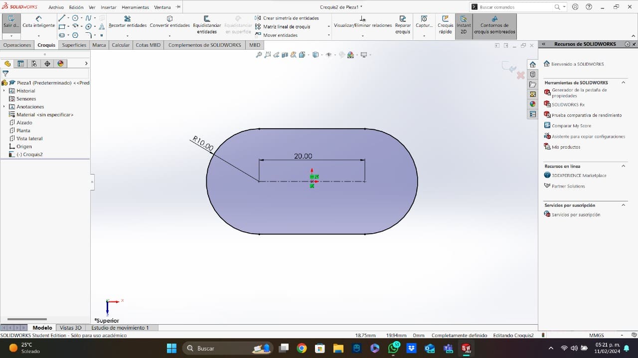
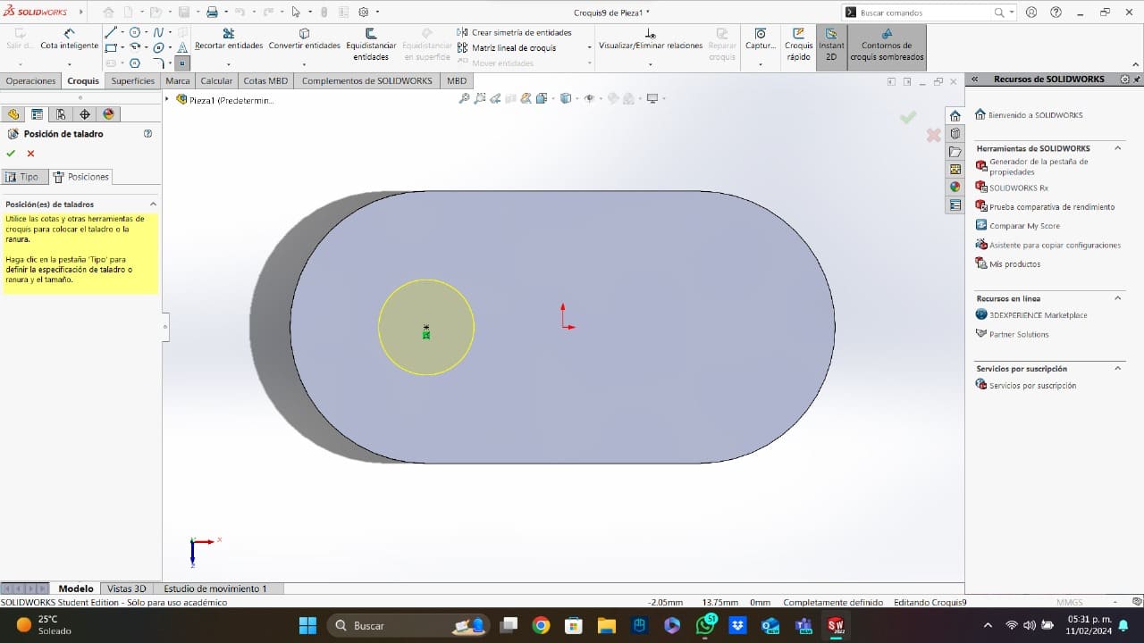
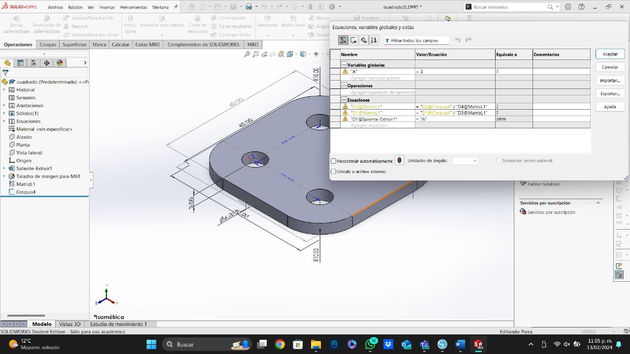
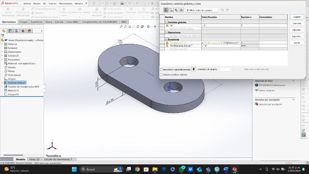
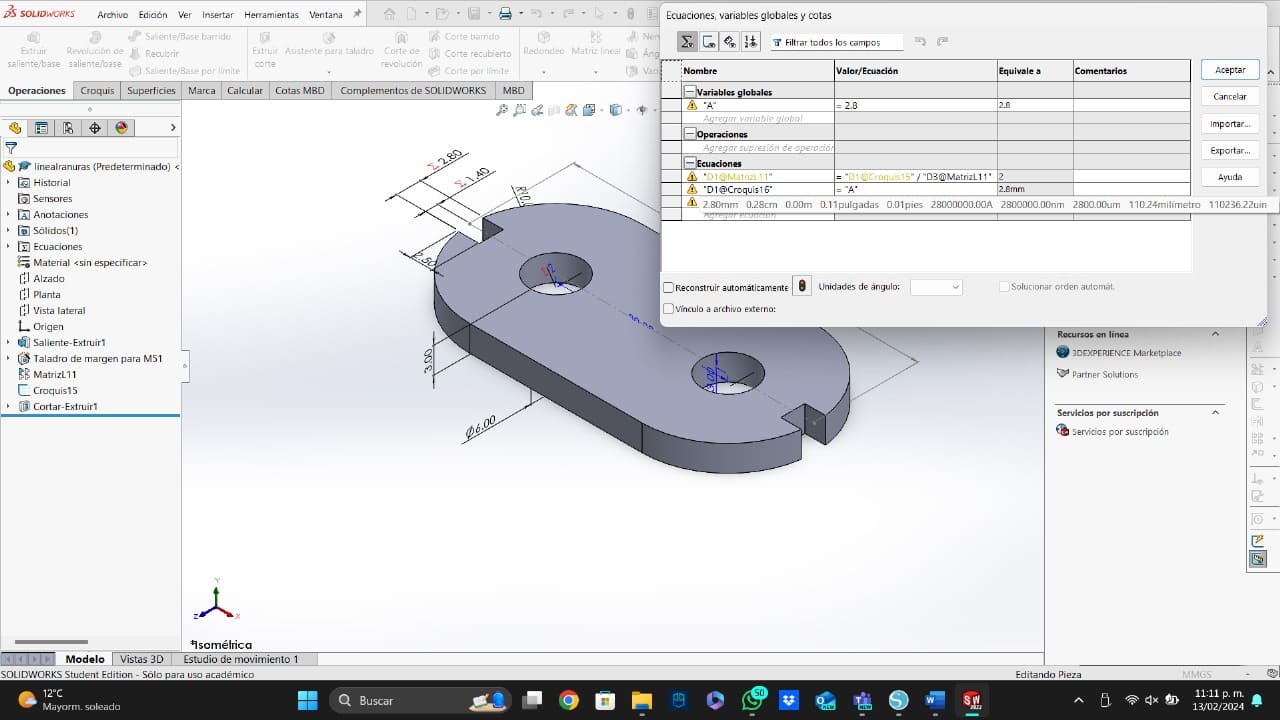
- Figure: After opening SolidWorks, I created an elongated hole to extrude it with my material thickness. After extruding, I used the drill feature to make one 6mm hole concentric with the elongated hole.
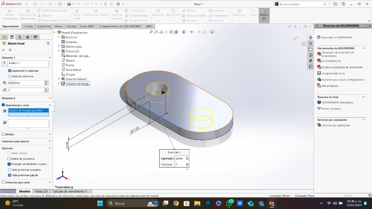
- The Matrix: To make the second hole of the piece, I used a lineal matrix on the X axis direction. After adding the matrix configuration, I created a redundant sketch with a construction line that represents the total lenght of my piece.
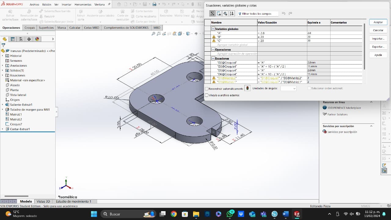
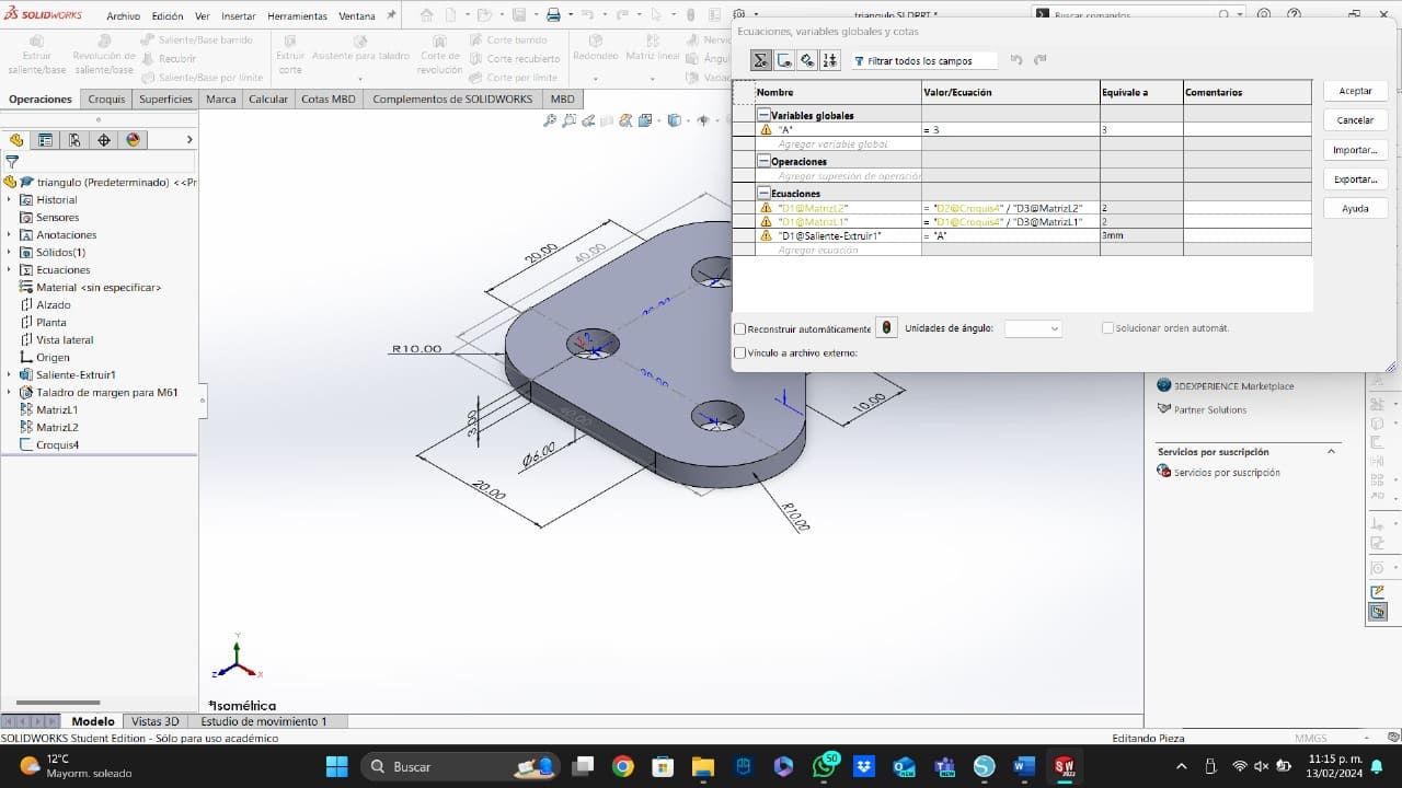
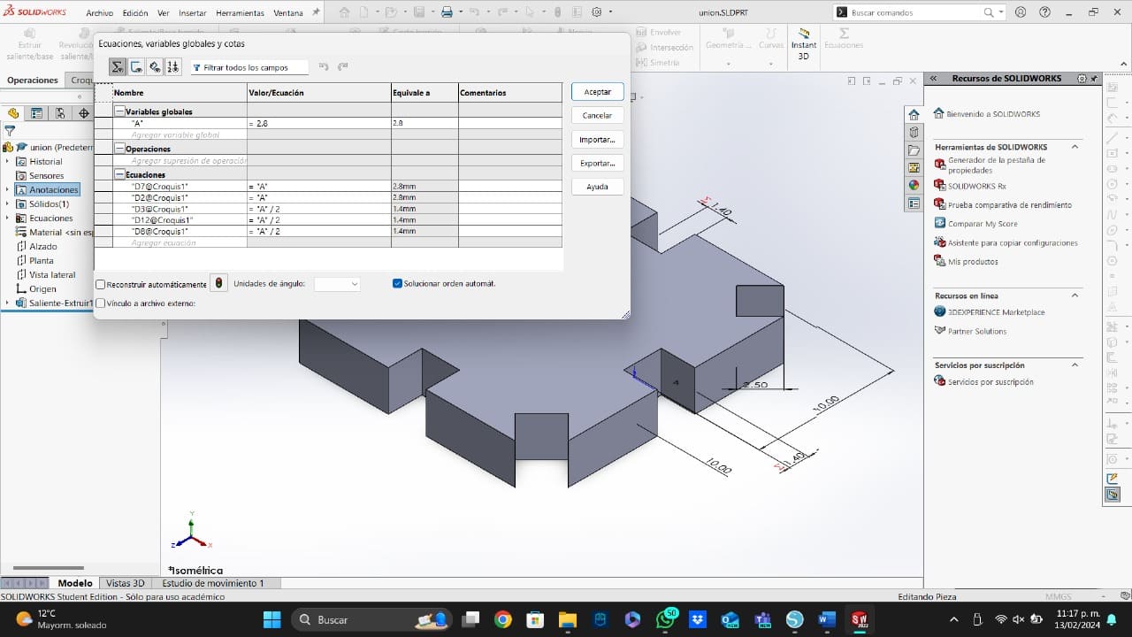
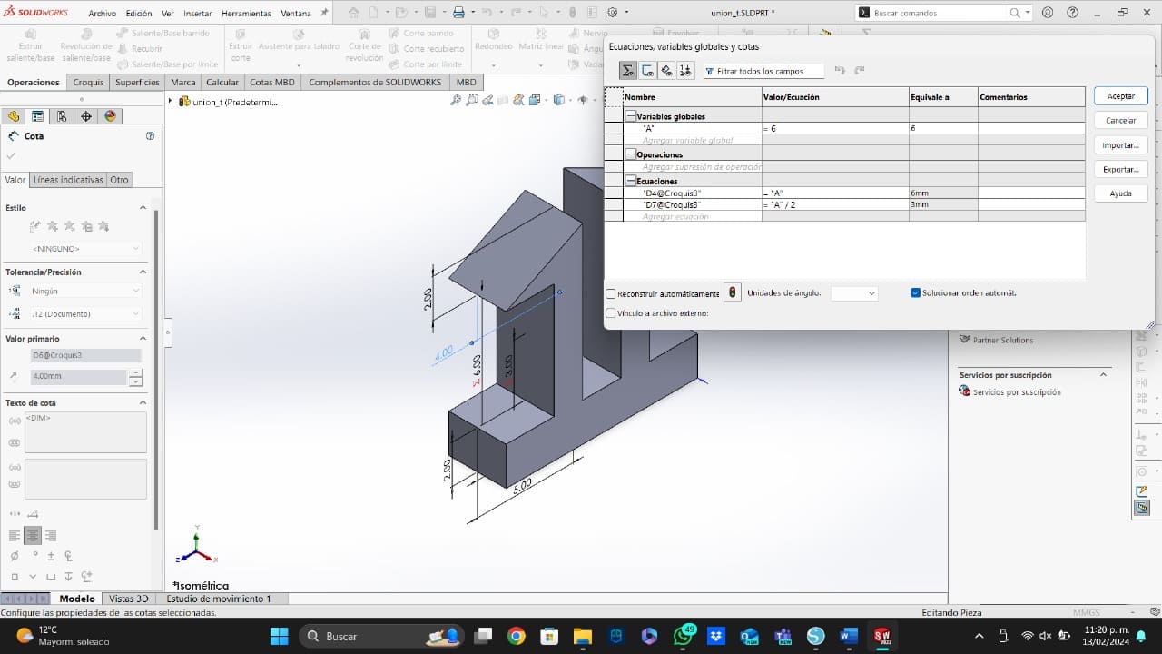
- The Ecuation: For all my pieces, I used the same ecuation with different settings. This ecuation consits in the definition of the number of holes by dividing the total lenght of my piece by the distance between the holes.
- Square: To create this piece, I make a square of 40mmx40mm, with a concentric hole of 6mm and a matrix to create the other 3 holes. I create the holes using a matrix to make the design parametric.
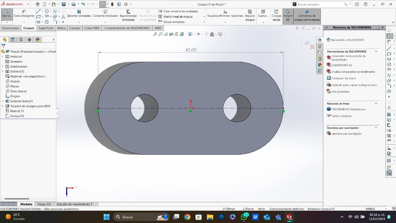
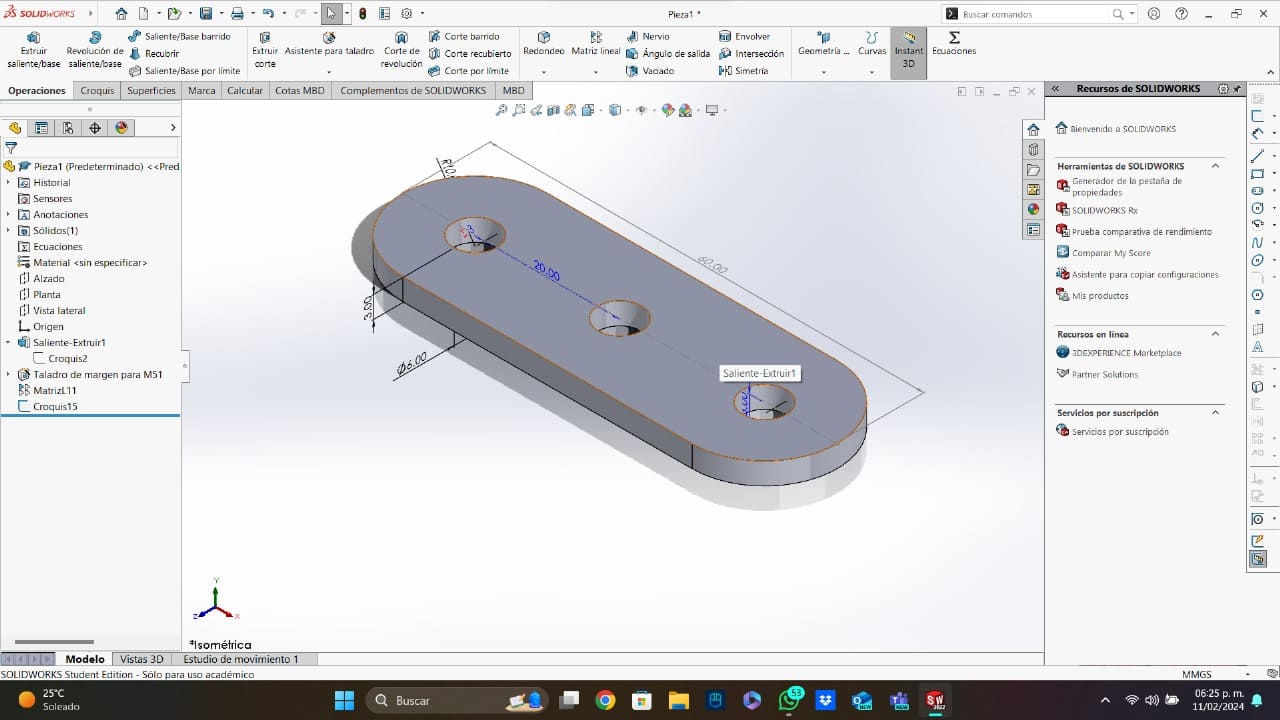
- Lineal: To create this piece, I make an elongated hole with a lenght of 40mm and a concentric hole of 6mm concentric with the middle circle. I use a lineal matrix to create another hole 20mm away.
- Lineal With Slot: For this design, I use the same design from the piece above, but I added some slots with the lenght of the material.
- L Form: This design is very simple, it consits in two elongated holes attached in one of the middle circles' axis. The lenght of the elongated holes is 40mm, with a concentric hole of 6mm with a separation of 20mm between each hole. The holes near the slots were made with a matrix, and the slots have the dimensions of 2.5mmx3mm.
- Triangle: This piece is very similar to the one above, but it was created without using the elongated hole feature. I created the triangle form using lines, and after having the form, I rounded the vertices. Like all the models, the lenght of the triangle was 40mm, with a rounded vertice with a radius of 10mm and a 6mm hole concentric to that rounded vertice. In this design, I used two different arrays, one in the direction of the Y axis and the other in the direction of the X axis. Each array has a lenght of 20mm between holes.
- Joint: To create the joint, I made a square of 20mmx20mm with two different slots of 2.5mmx3mm. I only made 2 slots, because the other ones were created with two different circular patterns.
- Circular Joints: To create this piece, I based my design in the "Snap Fit Joints" that were shown on the group task. I created two versions of the joint, the first one can link two pieces of 3mm mdf, and the other one, can link three pieces of 3mm mdf.

Using this short tutorial and thinking in how to use this same concept in every piece, I created six more different pieces that will help me to have a more complete parametric assembly kit.
The Parametric Kit
The image below shows all the pieces that my parametric kit has, but it is important to mention that I cut a lot of copies for each piece. All the original models has a separation between holes of 20mm, all of them have a lenght of 40mm, and all the edge fillets have a radius of 10mm. Now, I am going to show all the pieces and ecuations of my kit.
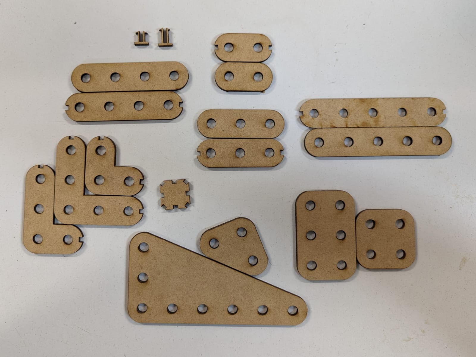
Now, I am going to explain all of my kit pieces:
Time to Cut
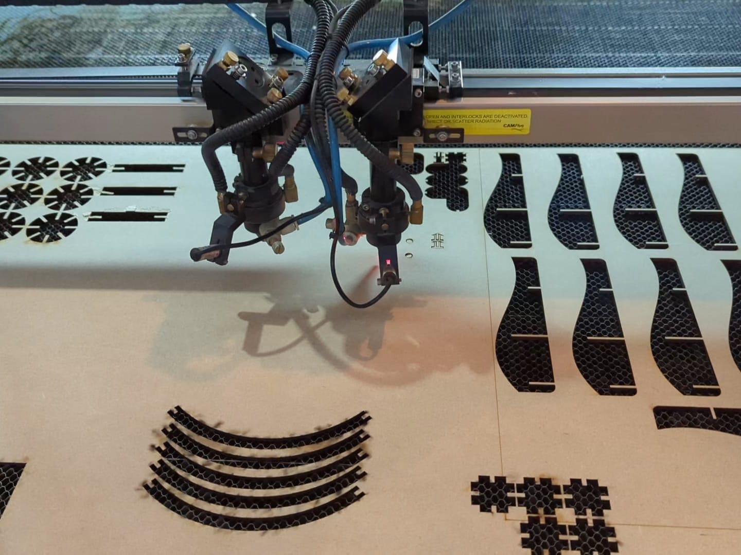
After saving the original model of my pieces and its dxf, I made some variations of each piece to have more possibilities of objects to assemble. I used the tolerances and cofiguration that we got on the group task. To visit the group task website, you can use this link to watch all the tests we made for the materials we will be using. The tolerance for the lost material was 0.2mm, the height used for the laser was 5mm, and the parameters used to cut were 55 of minimun power, 65 of maximun power, and 30mm/s of speed. Once in the laser software, I created a lot of arrays to cut a lot of copies of each piece.
After checking my workspace size and my cutting settings, I started the cutting process. This process took about 19 minutes to be completed, and after that, my kit was ready to build something.
At Least Two Different Things!!
After cutting my kit, it was time to test it builkding at least two different things. To be honest, I am not grat with the imagination, so I looked on my desk and I built things that can be useful on a workspace. In this case, I built a little penholder and a little base to put your phone while you are watching your favorite TV show.
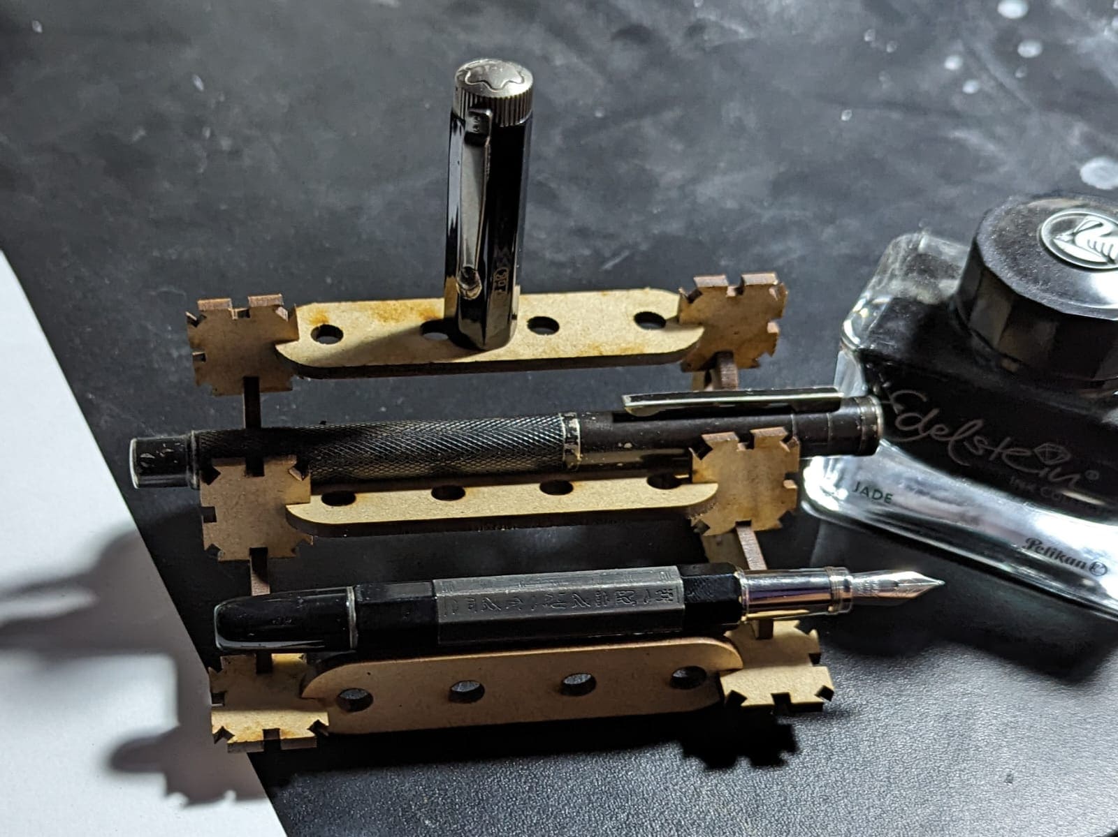
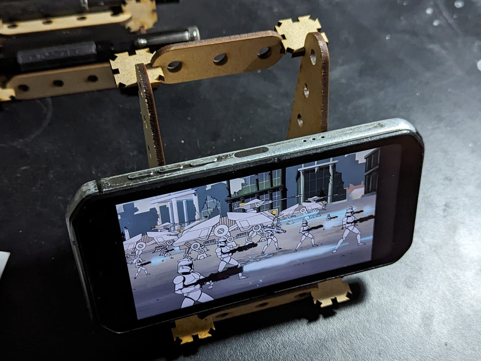
I think the intention of my kit is to kinda build what you want and need at the moment or, if you have a great imagination, more complex things. You can download the ZIP folder with all the DXF and SolidPart files here.
Vinyl Cut
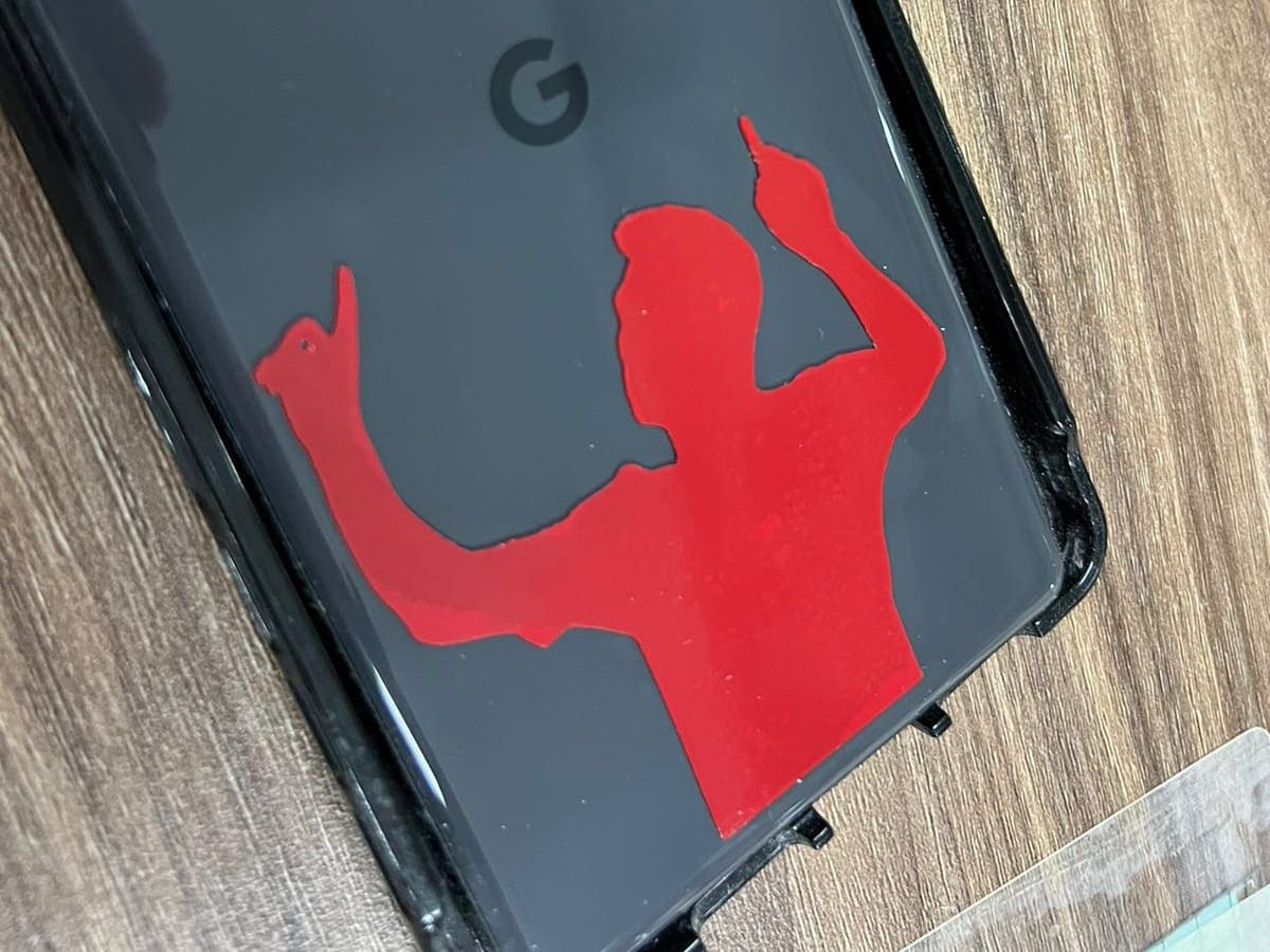
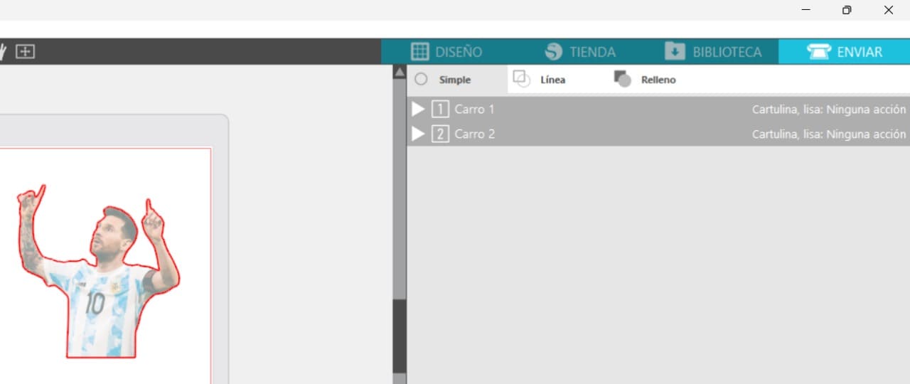
I think this was the easiest part of the task. In my case, I used the Silhouette America software tu cut my sticker. This is a free software that I download on their website. For this task, I looked for a photo of my favorite soccer player, Lionel Messi (the image needs to be on PNG format). This was because I wanted to have an sticker of him on the back part of my phone. The image I used for my sticker was this one:

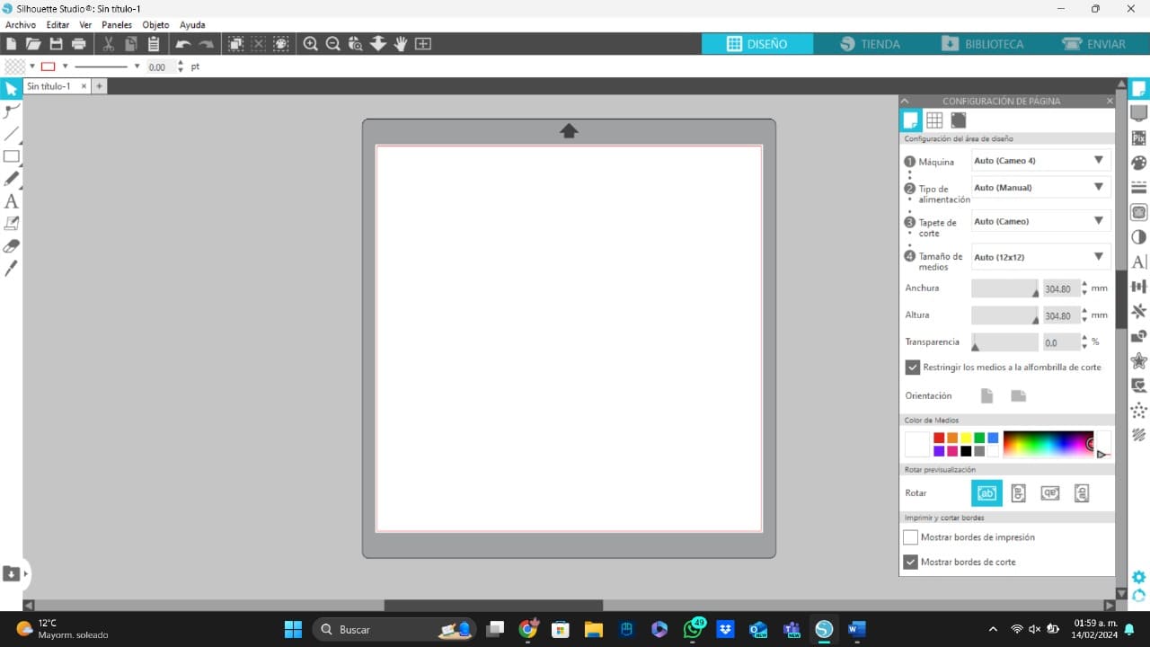
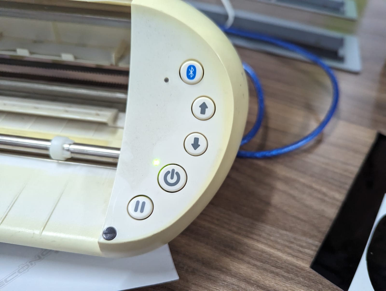
The Silhouette software is very easy to use, after connecting the vynil cutting machine to your computer, you are going to see the main page of the software:
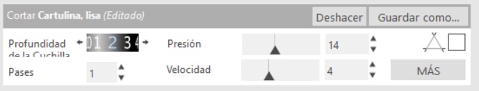
The next step is to open your PNG picture and the click on the "Enviar" button. After doing this, the software will vectorize automatically your picture. Now, I checked my parameters to got an excellent vynil cut. The parameters I used for my cut, were two on "Profundidad de la Cuchilla", one on "Passes", 14 on "Presión" and four on "Velocidad". I chose these parameters because with them the tool did cut to the necessary depth.
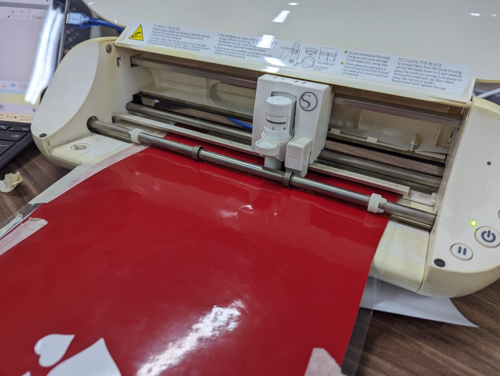
Before cutting, you need to prepare the cutting machine. To do this, you need to put the your material under the machine tool and then pull it with the control panel.
And that's all that you need to have your sticker, like I said before, I paste mine on my phone, this was the result: