14. Interface and Application Programming
This week's assignment was to develop an interface connecting to a microcontroller. You can check this week's group assignment in Ibero Puebla's group page.
Designing my interface.
For the design of my interface I used Qt Designer, Qt Designer is part of Qt, a widely used cross-platform graphical user interface (GUI) builder tool for creating highly customizable application interfaces. With its drag-and-drop functionality, Qt Designer simplifies the process of designing and laying out complex user interfaces. It supports a wide range of widgets, from buttons and text fields to layout managers, and allows these elements to be easily integrated into an application's interface. User interfaces designed in Qt Designer can be saved in XML format and later converted into Python or C++ code, making it a versatile tool for both quick prototyping and production-quality application development. Qt Designer can be used in various development environments, including PyQt and PySide for Python, as well as Qt for C++. This enables developers to fully utilize the extensive Qt library, which includes features for internationalization, accessibility, and multimedia support. Key features of Qt Designer include signal and slot editing, property editing, and support for custom widgets, making it a comprehensive tool for designing precise and functional user interfaces. Qt Designer remains the preferred choice for developing clean, professional applications that run seamlessly across desktop, mobile, and embedded platforms.
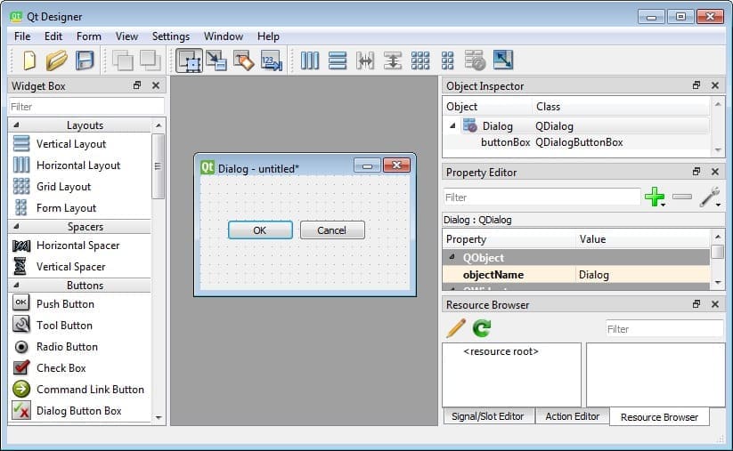
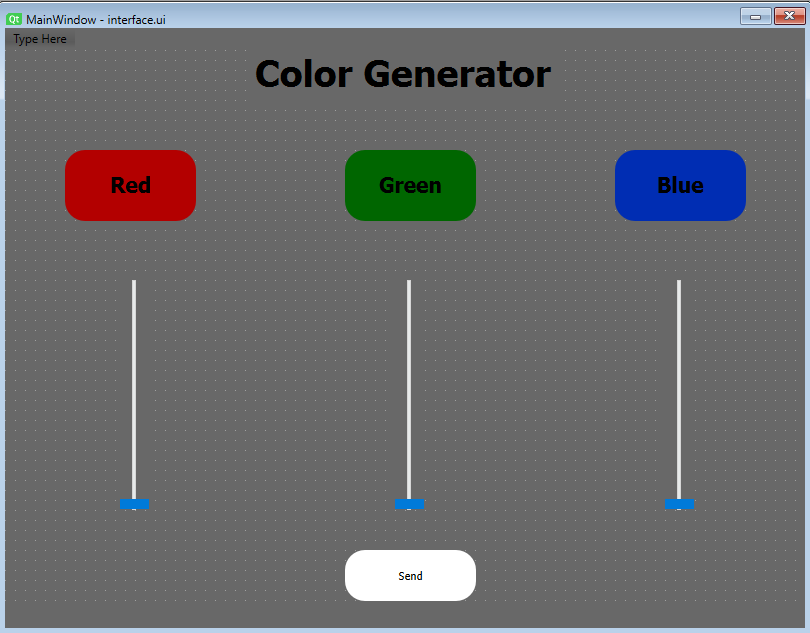
For my interface, I decided to make a color generator using the RGB system. It is an easy interface but a good start for someone new to this type of task. My interface only consists of 3 sliders, 3 labels for each color, and one button.
In order to make my interface I used three main tool bars.
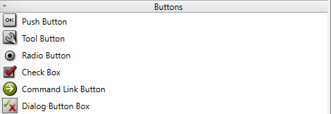
- Buttons
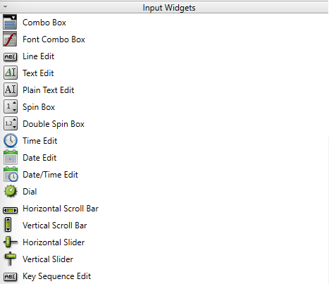
- Input Widgets
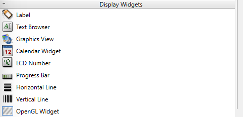
- Display Widgets
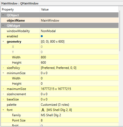
Using the property editor I positioned the objects and changed their height and width.
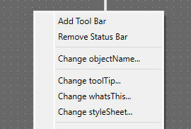
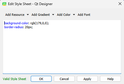
Finally I changed the style of the objects by right clicking the objects and selecting the "ChangestyleSheet". The style can be changed using css code.
Interface result
When the interface is designed in Qt Designer the file is saved as ".ui" but to connect the interface to the microcontroller the file needs to be converted into ".py". To do this we go to our interface folder and open the terminal. To convert the file we need to use this command: "pyuic6 -x name_of_file.ui -o interface.py".
If you modify the interface, you will need to reconvert it to Python using the previously mentioned command. However, doing this will overwrite any changes you have made. To prevent this, create a new Python file named "app.py" in the same folder and paste the following code into it:
                        from interfaz import *

                        class MainWindow(QtWidgets.QMainWindow, Ui_MainWindow):
                            def __init__(self, *args, **kwargs):
                                QtWidgets.QMainWindow.__init__(self, *args, **kwargs)
                                self.setupUi(self)
                                # The Logic


                        if __name__ == '__main__':
                            app = QtWidgets.QApplication([])
                            window = MainWindow()
                            window.show()
                            app.exec()
Now that we have that we can make our python logic around the code to send the instrctions to Arduino.
Python code
                        from interface import *
                        import serial
                        import sys

                        class MainWindow(QtWidgets.QMainWindow, Ui_MainWindow):
                            def __init__(self, *args, **kwargs):
                                QtWidgets.QMainWindow.__init__(self, *args, **kwargs)
                                self.setupUi(self)
                                self.serial = serial.Serial('COM11',9600)
                                self.red.sliderMoved.connect(self.red)
                                self.green.sliderMoved.connect(self.green)
                                self.blue.sliderMoved.connect(self.blue)
                                self.btn.clicked.connect(self.sendColors)

                            def sldred(self): #defines the red slider
                                sld_red = self.red.value()
                                print(sld_red)

                            def sldgreen(self): #defines the green slider
                                sld_green = self.green.value()
                                print(sld_green)

                            def sldblue(self): #define the blue slider
                                sld_blue = self.blue.value()
                                print(sld_blue)

                            def sendColors(self): #send the data of the slider to the microcontroller program
                                red_value = self.red.value()
                                yellow_value = self.green.value()
                                blue_value = self.blue.value()
                                self.serial.write(f"{red_value},{yellow_value},{blue_value}\n".encode())


                        if __name__ == '__main__':
                            app = QtWidgets.QApplication([])
                            window = MainWindow()
                            window.show()
                            app.exec()
Arduino Code
                        #include  //NeoPixel library

                            #define PIN 12         // Define NeoPixel pin
                            int Power = 11;
                            #define NUMPIXELS 1    // Number of NeoPixels
                            String String_received="0";

                            Adafruit_NeoPixel pixels(NUMPIXELS, PIN, NEO_GRB + NEO_KHZ800);

                            void setup() {
                              pixels.begin();           // Initialize the NeoPixels strip
                              Serial.begin(9600);       // Initialize the 9600 bps communication
                              pinMode(Power,OUTPUT);
                              digitalWrite(Power, HIGH);

                            }

                            void loop() {
                              if (Serial.available() > 0) {
                                // Wait to receive data from the format "R,G,B\n"
                                String_received = Serial.readStringUntil('\n');
                                int first = String_received.indexOf(',');
                                int last = String_received.lastIndexOf(',');

                                int red = String_received.substring(0, first).toInt();
                                int green = String_received.substring(first + 1, last).toInt();
                                int blue = String_received.substring(last + 1).toInt();

                                // Set the color of the first pixel
                                pixels.setPixelColor(0, pixels.Color(red, yellow, blue));
                                pixels.show();
                                Serial.print(String_received);

                              }
                              Serial.print(String_received);
                            }