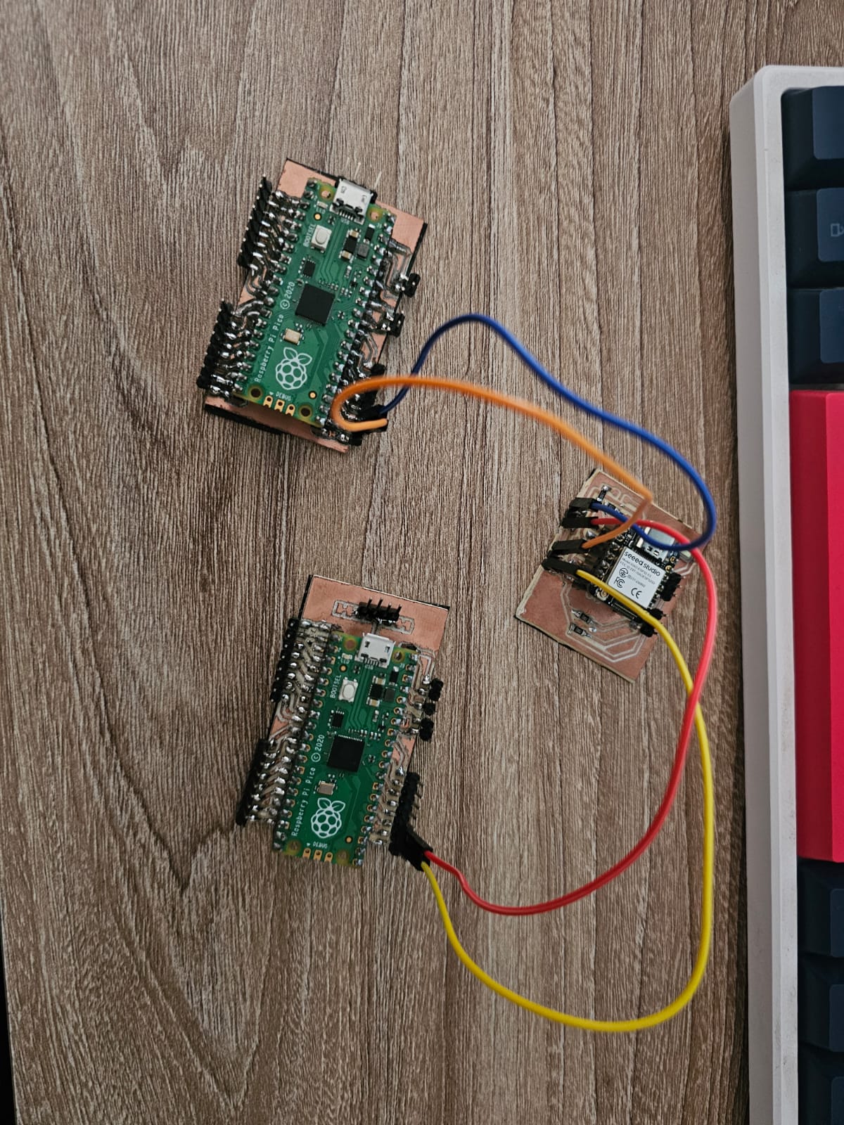
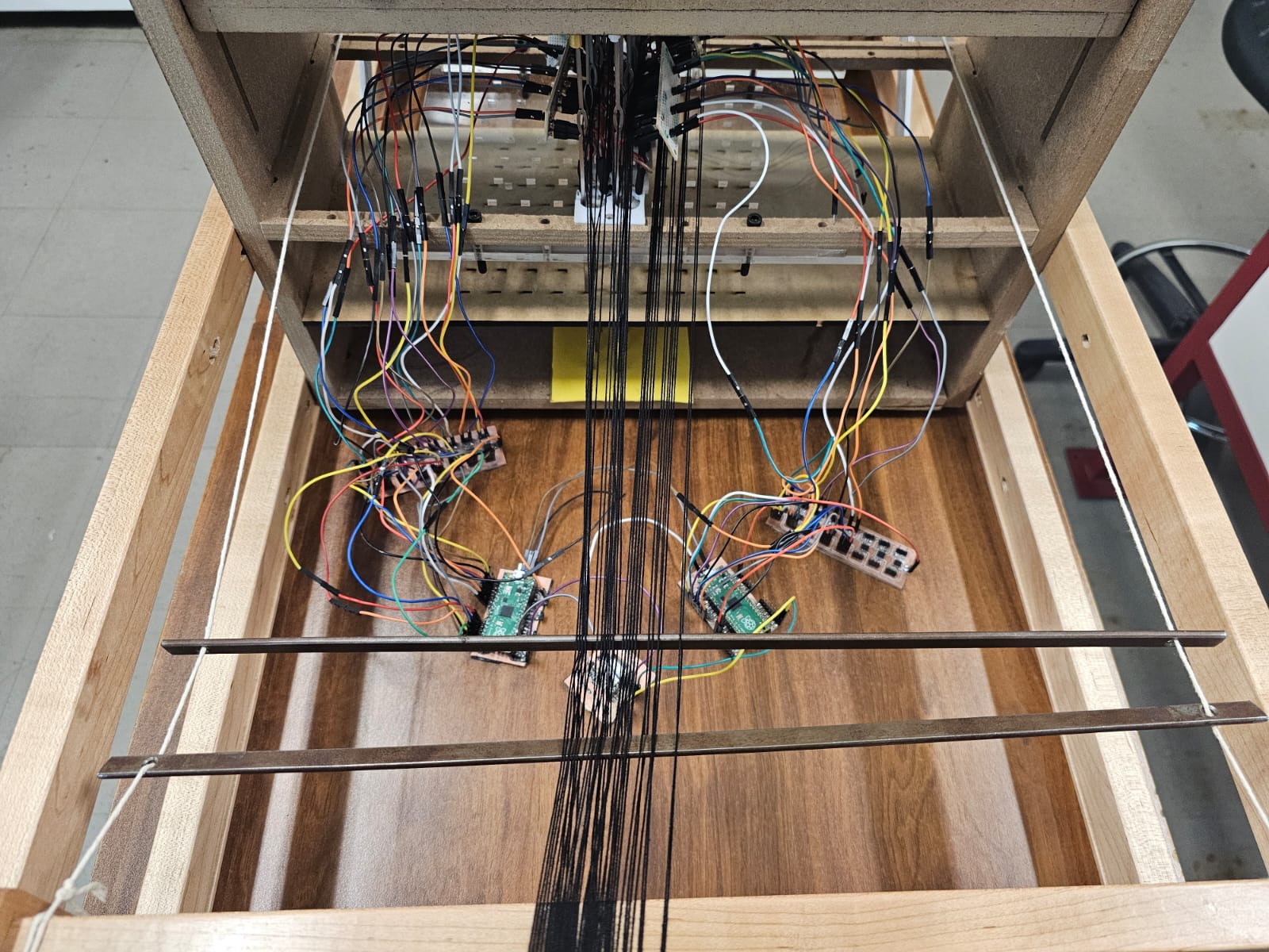
Networking and communications
This week assignment was to build and connect wired or wireless node(s) with network or bus addresses and a local interface
Group Assignment
The group assignment this week was to send a message between two projects.
You can find the group assignment in Ibero Puebla's web page.
I2C
I2C, or Inter-Integrated Circuit, is a communication protocol commonly used to connect multiple integrated circuits on the same board. It uses two lines for communication: SDA (Serial Data) and SCL (Serial Clock).
In an I2C connection, there are two main roles: the controller and the peripheral.
- Controller (Primary): This device initiates communication and controls the clock line (SCL). It sends commands and data to the peripheral devices.
- Peripheral (Secondary): These devices respond to the controller. They can send data back when requested but do not initiate communication on their own.
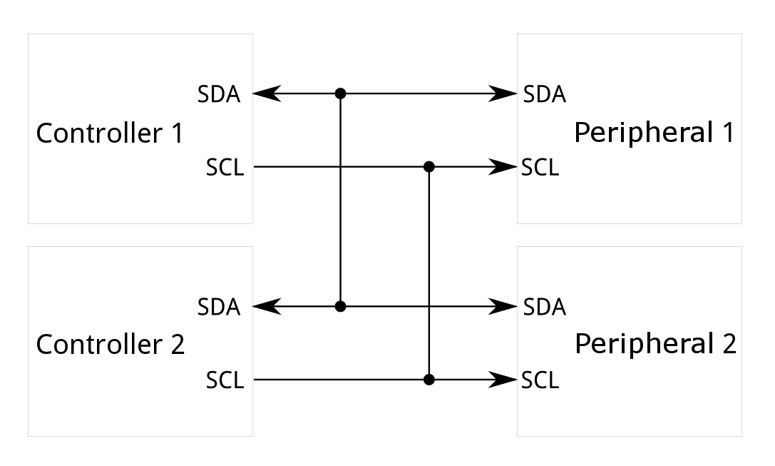
How it Works
- Start Condition: The controller sends a start condition by pulling the SDA line low while SCL is high, signaling the beginning of a communication session.
- Addressing: The controller then sends the 7-bit address of the peripheral it wants to communicate with, followed by a read/write bit. This address allows multiple devices to share the same bus.
- Acknowledgment: The peripheral with the matching address responds by pulling the SDA line low (acknowledge bit).
- Data Transfer: Data is transferred between the controller and the peripheral. Each byte sent is followed by an acknowledgment from the receiver.
- Stop Condition: The controller ends the communication by releasing the SDA line while SCL is high, signaling the stop condition.
PCBs
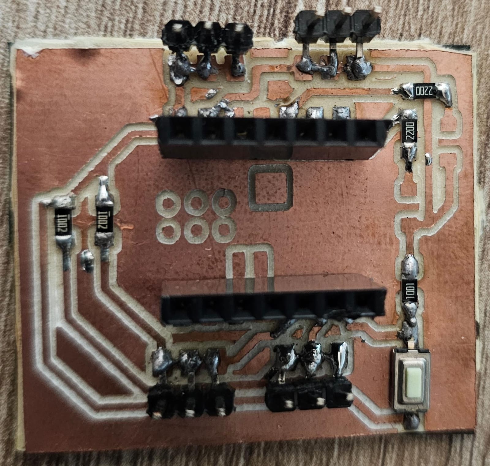
For this week's assignment, I designed two PCBs that will be used in my final project. I made one for the XIAO-2040, I'll use this one as my controller. The other one I made for the Raspberry PI pico 2040, this one is the peripheral.
Schematics and design
- XIAO-ESP32
- Raspberry PI pico 2040
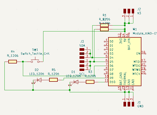
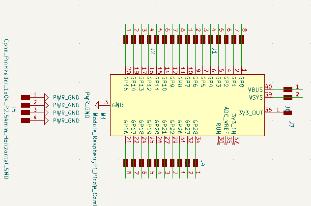
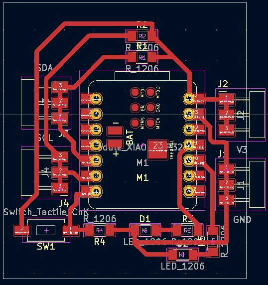
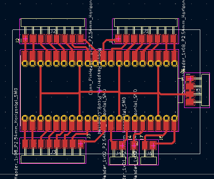
PCBs production
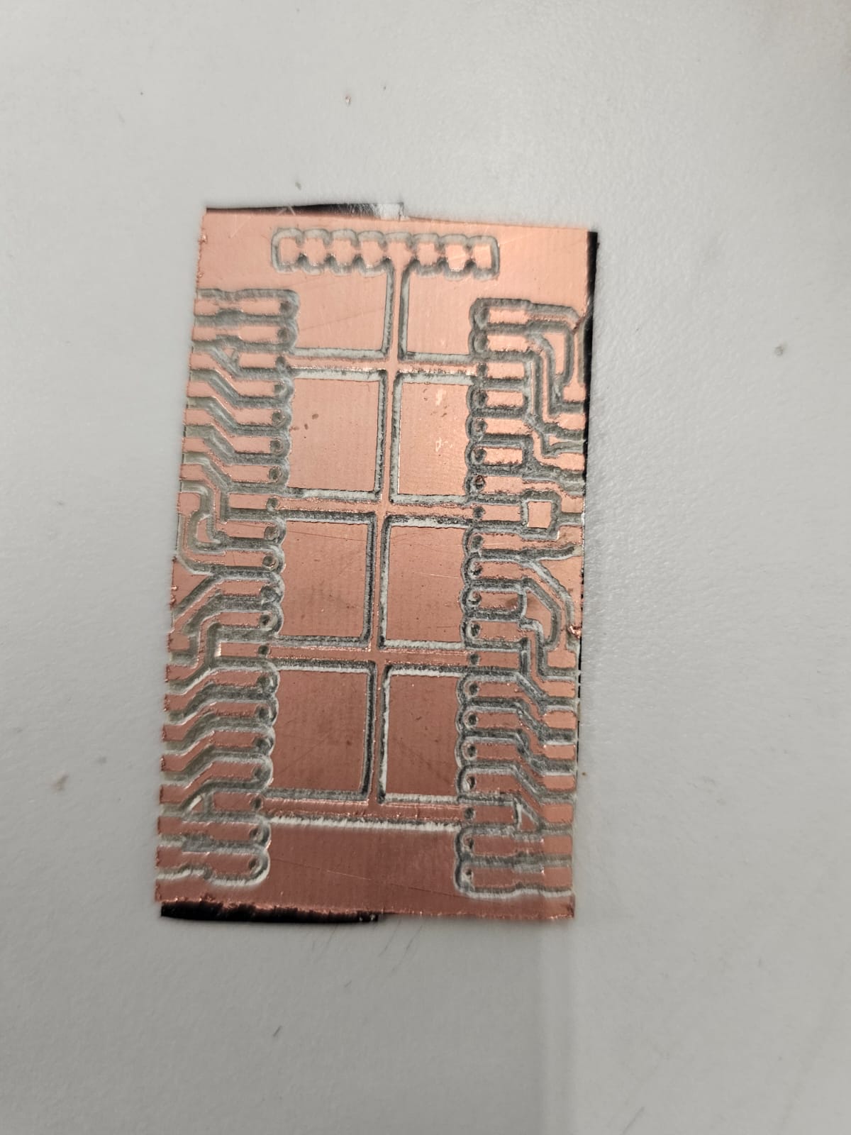
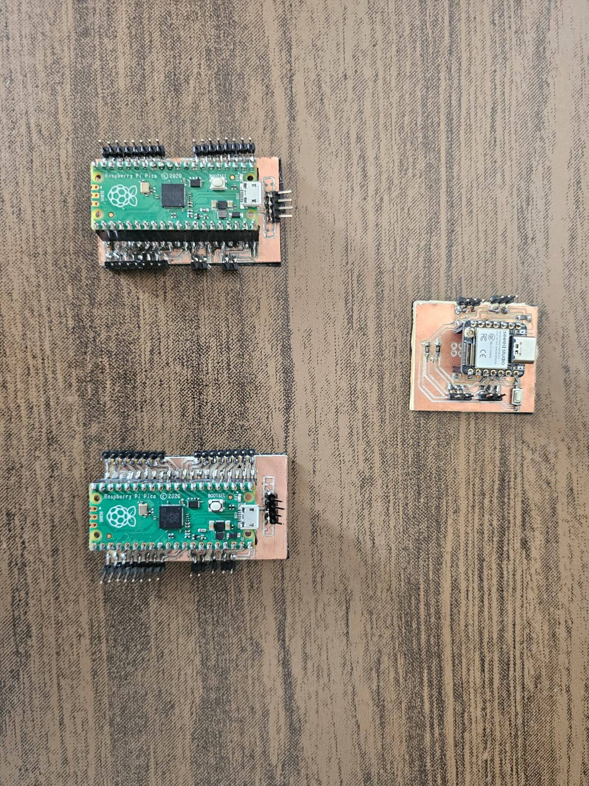
Coding
The hardest part of the code was to make a Python code that reads Excel cells with a preassigned value and sends them to the Arduino controller.
                    Python controler
                        import openpyxl
                        import serial
                        import time

                        puerto = '/dev/ttyUSB0'  # Replace with correct port
                        baudios = 9600
                        ser = serial.Serial('COM11', 115200, timeout=1)

                        # Wait a moment to communicate with arduino
                        time.sleep(2)

                        # Name of Excel file
                        archivo_excel = 'hello_world'

                        # Upload work book
                        wb = openpyxl.load_workbook("hello_world.xlsx")

                        # Select work sheet
                        ws = wb.active

                        # Read the cell value
                        value_range = ws ['A1':'P74']
                        text = []
                        indice = 0
                        for a, b, c, d, e, f, g, h, i, j, k, l, m, n, o, p in value_range:
                            text.append(str(a.internal_value) + str(b.internal_value) + str(c.value) + str(d.value) + str(e.value) + str(f.value) + str(g.value) + str(h.value) + str(i.value) + str(j.value) + str(k.value) + str(l.value) + str(m.value) + str(n.value) + str(o.value) + str(p.value))
                            #print(text)

                        #Close workbook after its done.
                        wb.close()
                        print(text[6])

                        dato = text + ';' #Ends the string
                        ser.write(dato.encode())
The Arduino codes were pretty simple, the first code is for the controller, it just receives data from the python code and depending on what it receives sends the instruction to the primary or secondary peripheral.
                    Controller Code
                            #include
                            String msj = " ";
                             byte diskP[] = {'A','B','C','D','E','F','G','H','I','J','K','L','M','N','O','P'};
                             byte diskN[] = {'a','b','c','d','e','f','g','h','i','j','k','l','m','n','o','p'};

                            // the setup function runs once when you press reset or power the board
                            void setup() {
                              // initialize digital pin LED_BUILTIN as an output.
                              Serial.begin(115200);
                               Wire.begin();
                            }

                            // the loop function runs over and over again forever
                            void loop() {

                              if(Serial.available()>0){
                                Serial.print("Dato recibido");
                                msj += Serial.readStringUntil(';'); //Receives a string of data from the Python code
                                for(int i=0; i<8; i++){
                                  Wire.beginTransmission(1);  // Convey to primary p[eripheral]
                                  if(msj[i]=='1')
                                  {
                                    Wire.write(diskP[i]);
                                  }
                                  else if(msj[i]=='0')
                                  {
                                    Wire.write(diskN[i]);
                                  }
                                  Wire.endTransmission();
                                }
                                for (int i=8; i<16; i++){
                                  Wire.beginTransmission(2);  // Convey to secondary peripheral
                                  if(msj[i]=='1')
                                  {
                                    Wire.write(diskP[i]);
                                  }
                                  else if(msj[i]=='0')
                                  {
                                    Wire.write(diskN[i]);
                                  }
                                  Wire.endTransmission();
                                }
                              }
                                // wait for a second
                            }
The peripherals just received data and executed a certain command depending on what it receives.
#include
const int Ap = 0;
const int As = 1;
const int Bp = 2;
const int Bs = 3;
const int Cp = 4;
const int Cs = 5;
const int Dp = 6;
const int Ds = 7;
const int Ep = 8;
const int Es = 9;
const int Fp = 10;
const int Fs = 11;
const int Gp = 12;
const int Gs = 13;
const int Hp = 14;
const int Hs = 15;
void setup() {
// initialize digital pin LED_BUILTIN as an output.
pinMode(Ap, OUTPUT);
pinMode(As, OUTPUT);
pinMode(Bp, OUTPUT);
pinMode(Bs, OUTPUT);
pinMode(Cp, OUTPUT);
pinMode(Cs, OUTPUT);
pinMode(Dp, OUTPUT);
pinMode(Ds, OUTPUT);
pinMode(Ep, OUTPUT);
pinMode(Es, OUTPUT);
pinMode(Fp, OUTPUT);
pinMode(Fs, OUTPUT);
pinMode(Gp, OUTPUT);
pinMode(Gs, OUTPUT);
pinMode(Hp, OUTPUT);
pinMode(Hs, OUTPUT);
// We join this code with the I2C and establish it as the peripheral 1.
Wire.begin(1);
}
// the loop function runs over and over again forever
void loop() {
if(Wire.available() > 0) {
char command = Wire.read(); // Reads the data send by the controller
if (command = 'A'){
Serial.print("+Disk1");
digitalWrite(Ap, HIGH);
digitalWrite(As, LOW);
delay(500);
}
else if (command = 'a'){
Serial.print("-Disk1");
digitalWrite(Ap, LOW);
digitalWrite(As, HIGH);
delay(500);
}
else if (command = 'B'){
Serial.print("+Disk2");
digitalWrite(Bp, HIGH);
digitalWrite(Bs, LOW);
delay(500);
}
else if (command = 'b'){
Serial.print("-Disk2");
digitalWrite(Bp, LOW);
digitalWrite(Bs, HIGH);
delay(500);
}
else if (command = 'C'){
Serial.print("+Disk3");
digitalWrite(Cp, HIGH);
digitalWrite(Cs, LOW);
delay(500);
}
else if (command = 'c'){
Serial.print("-Disk3");
digitalWrite(Cp, LOW);
digitalWrite(Cs, HIGH);
delay(500);
}
else if (command = 'D'){
Serial.print("+Disk4");
digitalWrite(Dp, HIGH);
digitalWrite(Ds, LOW);
delay(500);
}
else if (command = 'd'){
Serial.print("-Disk4");
digitalWrite(Dp, LOW);
digitalWrite(Ds, HIGH);
delay(500);
}
else if (command = 'E'){
Serial.print("+Disk5");
digitalWrite(Ep, HIGH);
digitalWrite(Es, LOW);
delay(500);
}
else if (command = 'e'){
Serial.print("-Disk5");
digitalWrite(Ep, LOW);
digitalWrite(Es, HIGH);
delay(500);
}
else if (command = 'F'){
Serial.print("+Disk6");
digitalWrite(Fp, HIGH);
digitalWrite(Fs, LOW);
delay(500);
}
else if (command = 'f'){
Serial.print("-Disk6");
digitalWrite(Fp, LOW);
digitalWrite(Fs, HIGH);
delay(500);
}
else if (command = 'G'){
Serial.print("+Disk7");
digitalWrite(Gp, HIGH);
digitalWrite(Gs, LOW);
delay(500);
}
else if (command = 'g'){
Serial.print("-Disk7");
digitalWrite(Gp, LOW);
digitalWrite(Gs, HIGH);
delay(500);
}
else if (command = 'H'){
Serial.print("+Disk8");
digitalWrite(Hp, HIGH);
digitalWrite(Hs, LOW);
delay(500);
}
else if (command = 'h'){
Serial.print("-Disk8");
digitalWrite(Hp, LOW);
digitalWrite(Hs, HIGH);
delay(500);
}
else{
digitalWrite(Ap,LOW);
digitalWrite(As,LOW);
digitalWrite(Bp,LOW);
digitalWrite(Bs,LOW);
digitalWrite(Cp,LOW);
digitalWrite(Cs,LOW);
digitalWrite(Dp,LOW);
digitalWrite(Ds,LOW);
digitalWrite(Ep,LOW);
digitalWrite(Es,LOW);
digitalWrite(Fp,LOW);
digitalWrite(Fs,LOW);
digitalWrite(Gp,LOW);
digitalWrite(Gs,LOW);
digitalWrite(Hp,LOW);
digitalWrite(Hs,LOW);
}
}
delay(30);
}
The second peripheral is the same code but with different variables
Set up
I'm going to use this week's assignment to implement it into my final project, this pcbs will control the mechanism of the loom that selects which heddles go up and which ones stay down. Since the project is being patented here in Ibero Puebla I can't show how the mechanism works explicitly.
