4. Electronics Production
This week's task is to make and test a microcontroller development board.
Group assignment
In Fablab Puebal we have three Mini-Mill machines, this is ROLAND SRM-20, MDX-20, Lunyee. For this week's assignment, I initially wanted to use the SRM-20 due to the precision of its cuts, but there were sometimes related problem and I ended up using the Lunyee. This information can be found in Ibero Puebl's group page: Fab lab Puebla
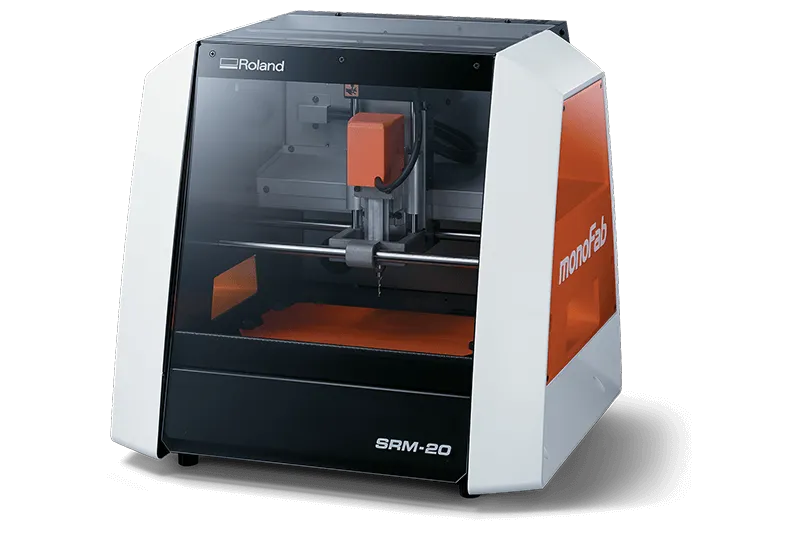
SRM-20 specifics:
- Cutable Material: Modeling Wax, Chemical Wood, Foam, Acrylic, Polyacetal, Acrylonitrile Butadiene Styrene (ABS), Printed Circuit Boards
- Operational Travels in X, Y, and Z: 203.2 mm (X) × 152.4 mm (Y) × 60.5 mm (Z)
- Operation Speed: From 6 mm/min to 1,800 mm/min
- Spindle Rotation Speed: Adjustable from 3,000 RPM to 7,000 RPM
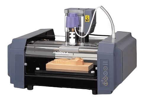
MDX-20 specifics:
- Operational Travels in X, Y, and Z: 203.2 mm (X) × 152.4 mm (Y) × 60.5 mm (Z)
- Operation Speed: 0.1 to 15 mm/sec.
- Spindle Rotation Speed: 6500 RPM
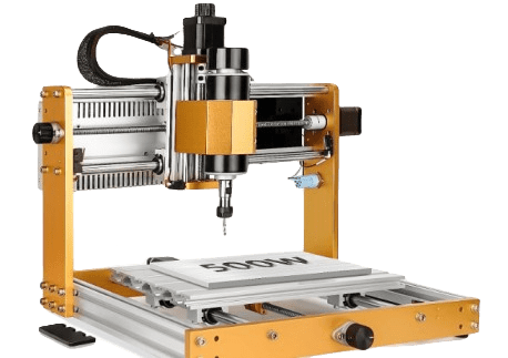
Lunyee specifics:
- Cutable Material: Modeling Wax, Chemical Wood, Foam, Acrylic, Polyacetal, Acrylonitrile Butadiene Styrene (ABS), Printed Circuit Boards
- Operational Travels in X, Y, and Z: 300 mm (X) × 180 mm (Y) × 80 mm (Z)
- Operation Speed: 2000 mm/min
- Spindle Rotation Speed: 12000 RPM
Tools
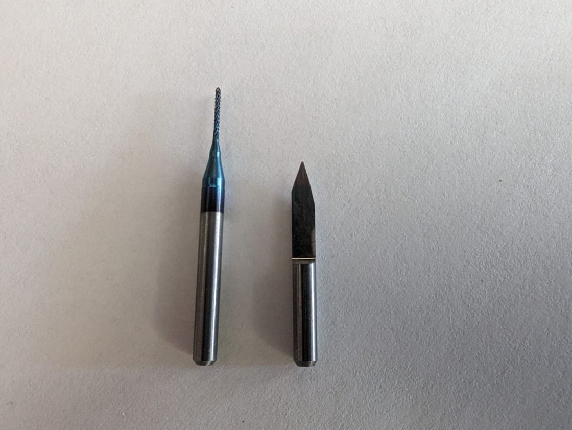
Creating a PCB consist of two main steps, the engraving and the cutting. For the engraving we used the 15-degree V-bit and for cutting we used 0.8mm diameter two flute end Mill
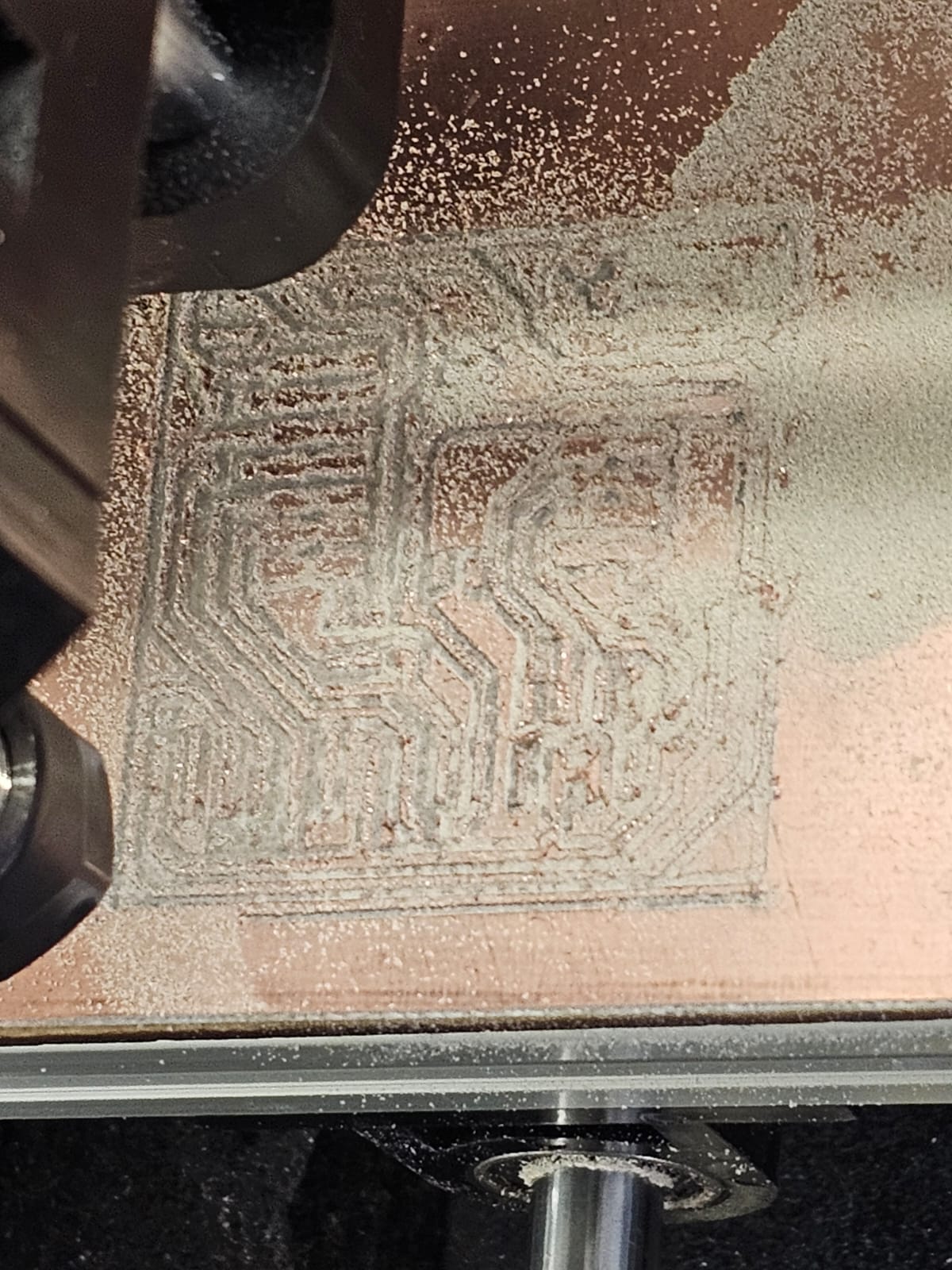
Creating my pcb
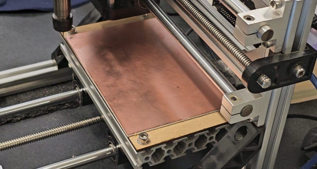
Milling is a very delicate process in which every step has to be carefully done. For the PCB I used a 10cm x 15 cm copper plate that I pasted to a sacrificial bed, in order to protect the bed of the mini-mill and to support the copper plate itself.
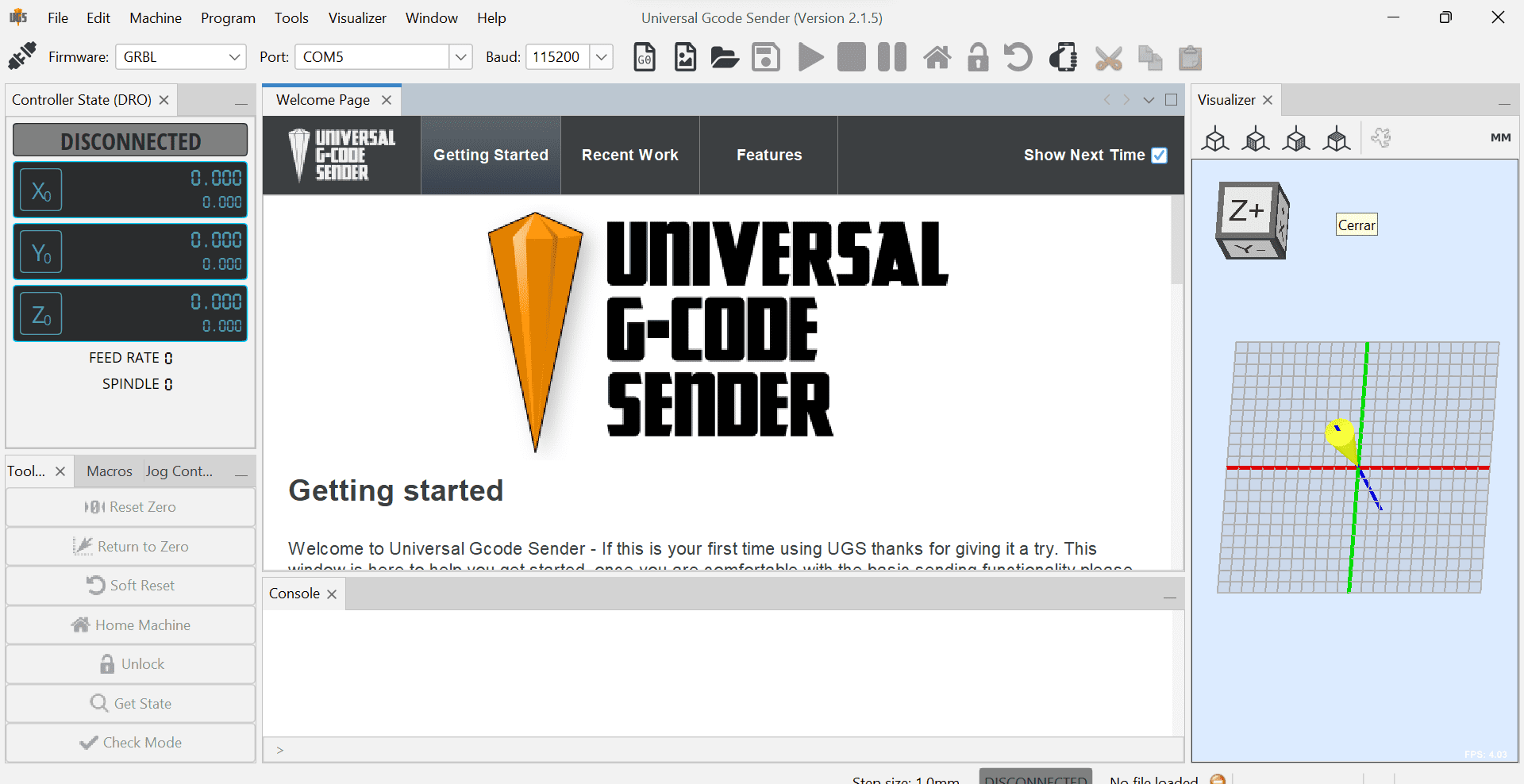
The next step is to calibrate the machine, I bolted my sacrificial bed into the mini-mill bed to secure it. Then I calibrated the X, Y and Z axis by using the Universal G-code sender software.
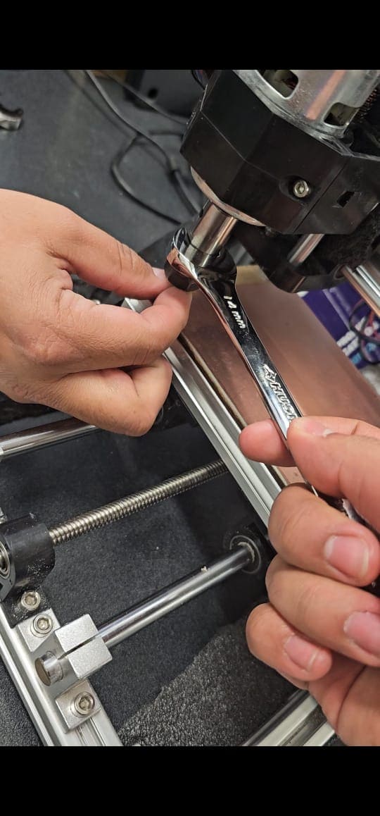
After I'd set my origin points in the X and Y axis I proceeded to calibrate the Z axis, to do so I used two wrenchs, one of 17mm and another of 14mm, to manually elevate my tool 3mm above the plate. The next step is to manually lower the Z axis until it touched the plate, once that's done It's ready to cut. I followed this series of steps for both the engraving and the cutting of the PCB.
How to upload the PCB?
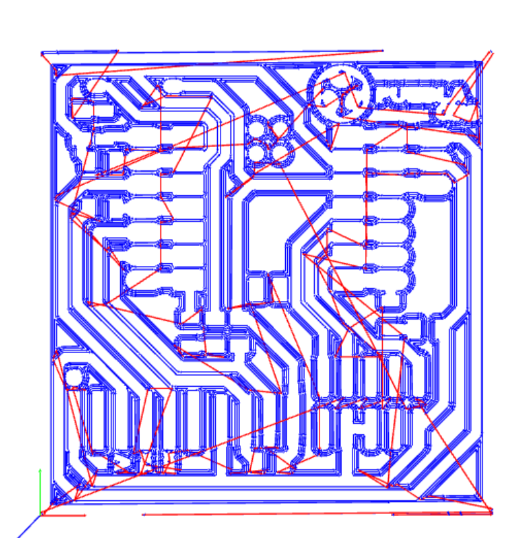
I had an image of the design of the PCB in JPG format, to pass it to the format the Mini-mill needed I used a software called ModesCE.

The steps to upload something to Modes Ce are the following:
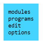
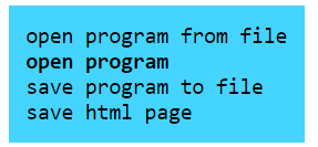
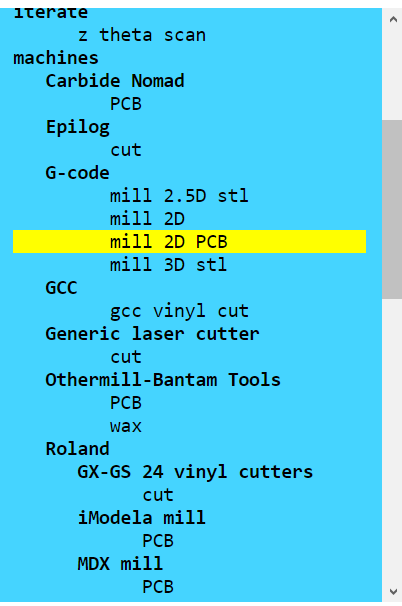
First right click will open a menu, select programs, select the option "open program", select the option "Mill 2D PCB.
This will open an option three, it may seem overwhelming but I just made small modifications to it.
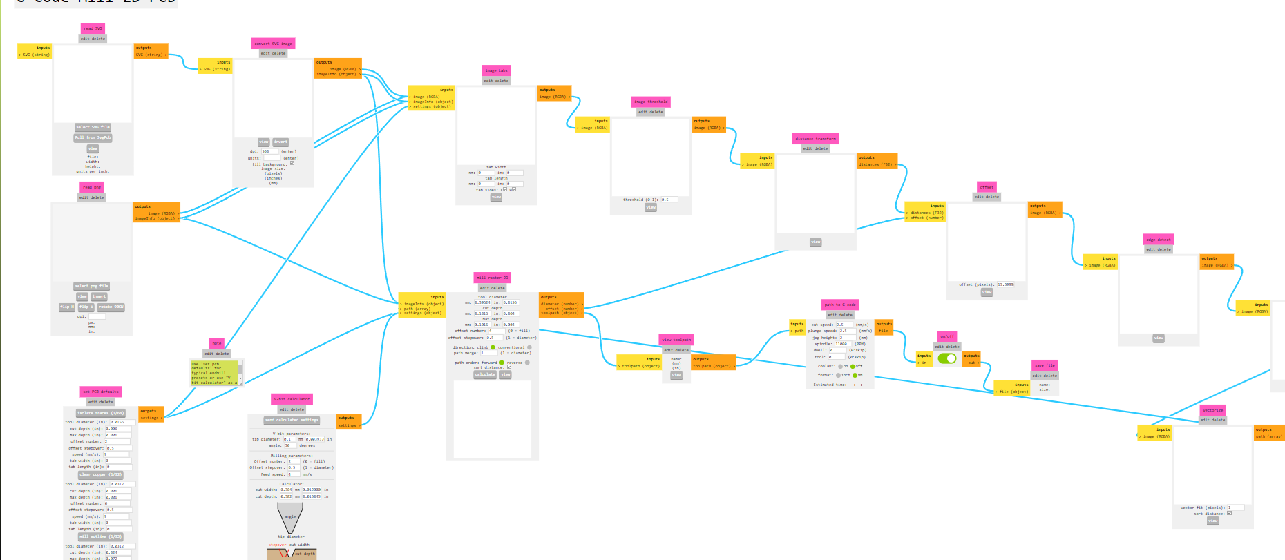
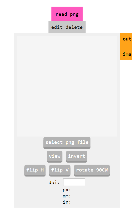
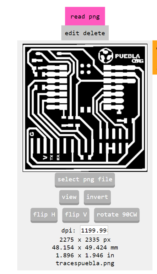
The first thing I did was to upload my PCB design in PNG format, I did this using the "Read png" tool.
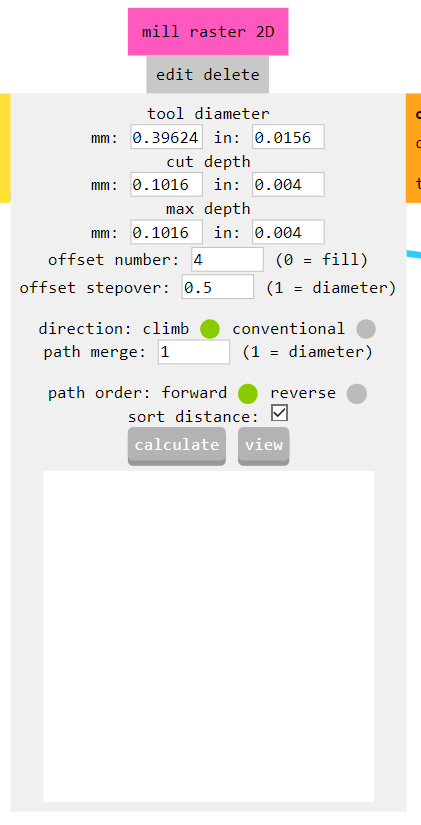
After that, I used the Mill rester 2D to calculate the path of the tracing. This generates a .cn document that will be uploaded to the mini-mill software.
Results
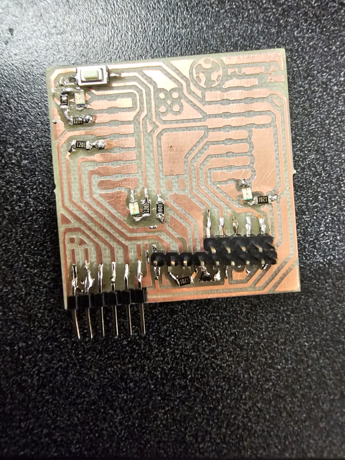
Soldering
For the soldering tools I used tin and cautin.
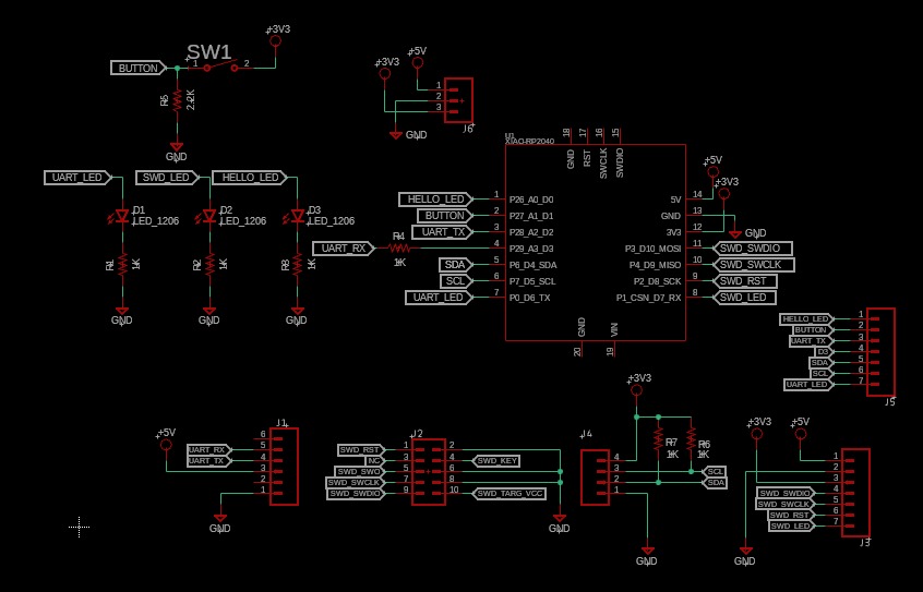
The electronic components of the PCB consist of: 7 resistors, 3 LED's, 21 pin's and a XIAO-RP2040.
First I solder the small components, the LEDs, the resistors, and the pins.
Finally I just solder the XIAO-RP2040.
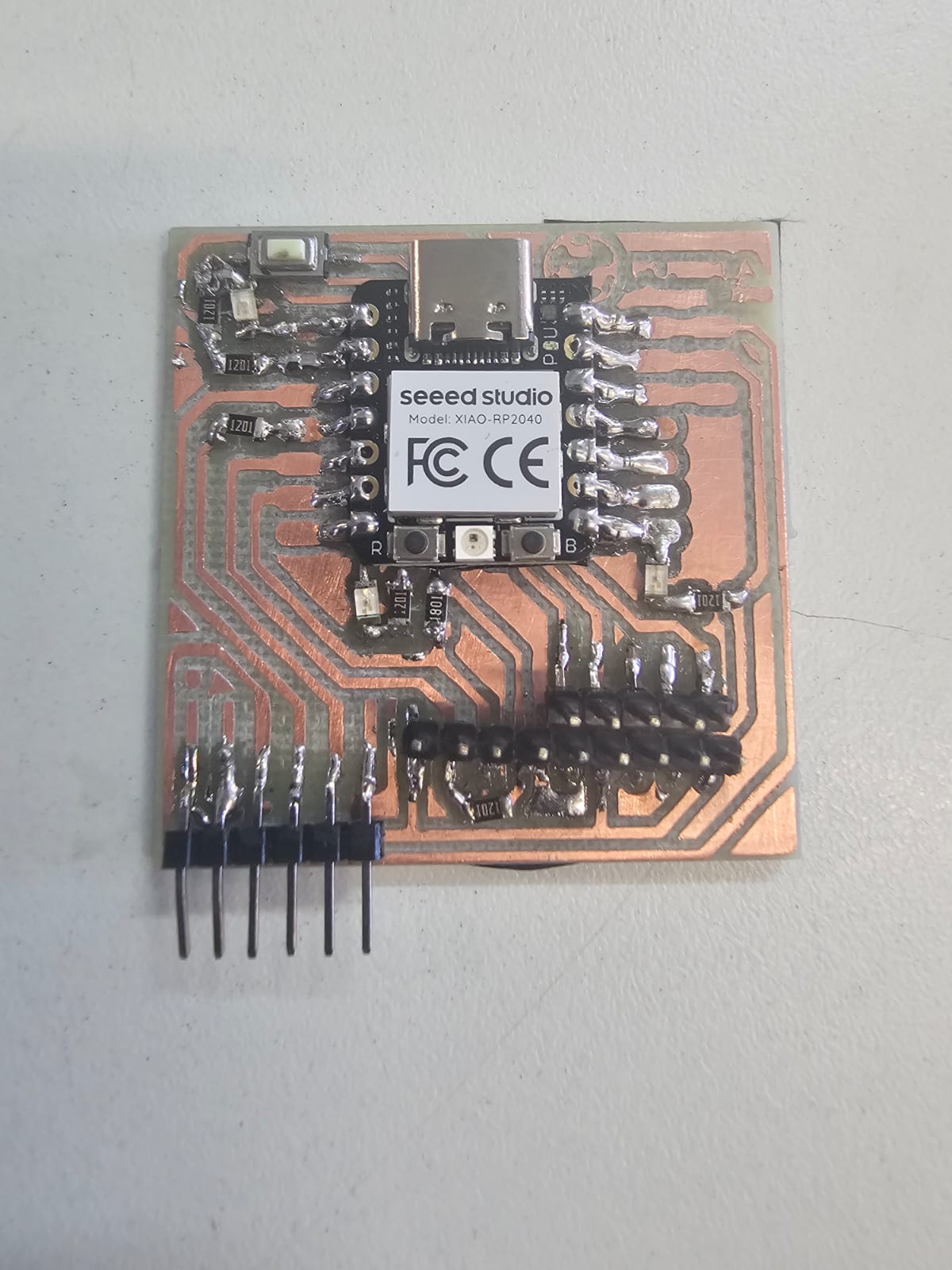
Code and Testing
I used Arduino to upload a preamde code to test my PCB.