1. Computer aided design
This week I worked on modeling some objects/parts for a possible final project.
Softwares I used and how to model in them
The programs I decided to try were CATIA and SolidWorks, this is due to mainly two reasons, the first one is that my school gives me free access to both programs, the other reason is that I am somewhat familiar with them so I figured it wouldn't be so hard to learn how to use them properly. This week's models are two pieces of an assembly. One part I'll show how I did it in SolidWorks, and in the other part I'll show how I did it in CATIA.
Modeling in SolidWorks
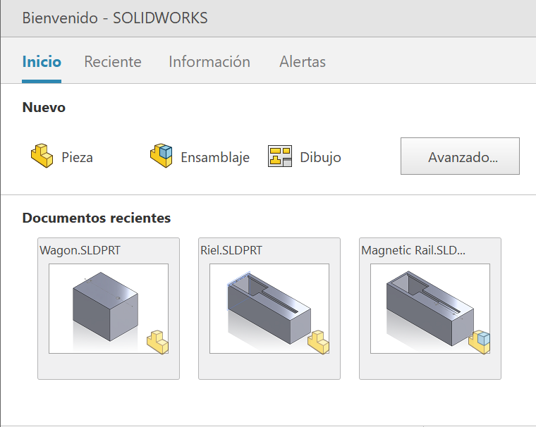
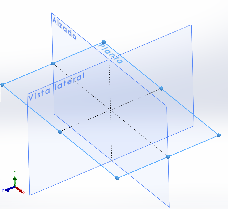
When SolidWorks is uploaded the first thing that should appear is a menu with different options. These options are: Part (pieza), assembly (ensamblaje) or drawing (dibujo). Depending on what you want to do.Beginning with my part I selected a plane in wich I created a first sketch.
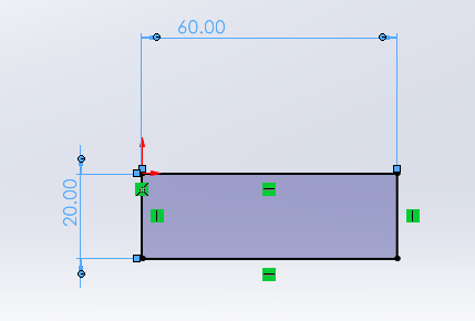
When a sketch is generated a toolbar will appear at the top of the screen, here we can find tools like the smart dimension, which allows the user to adjust the size of any part of a figure generated in the sketch. Another essential tool I used is the geometric figure generator, as the name indicates, it generates a variety of geometrical figures and lines that help the user generate its part.

Once I've finished the sketch, you have to exit it. After that another toolbar will appear, this one is used to turn that sketch into a 3D part by modifying its volume, making cuts, and making it shallow amongst other things. For my part, I used the extrude tool to give volume to my sketch and then I made it shallow with the shell tool (empty in some programs).

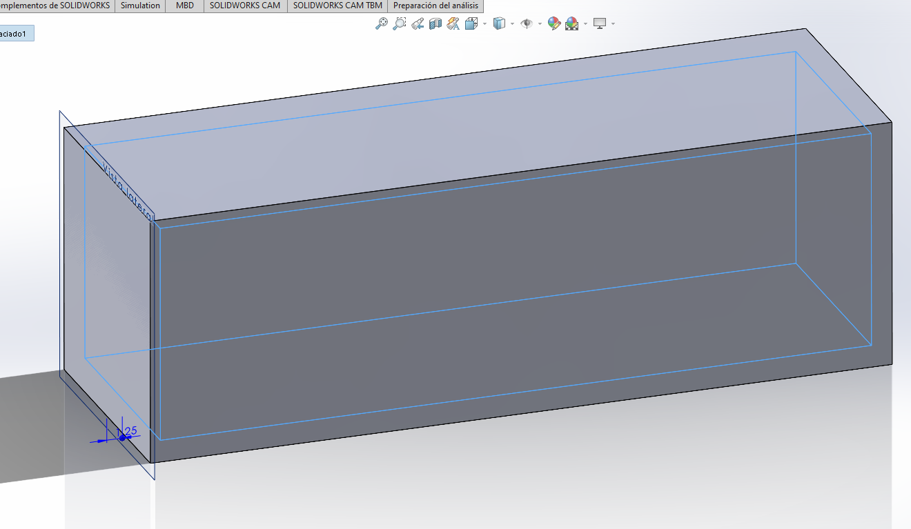
Sketches aren´t restricted to planes, they can also be created in flat faces of figures. I created a sketch in the top face of my part. Using to rectangles and the tools I've already mentioned, I created an opening that I will later use in an assembly. In order to give depth to my sketch I used a tool called extrude cut, with this I can specify how deep I want my cut to go. Solid Works allows you to change the properties of different cuts that originated from the same sketch.
Final SolidWorks 3D model
Modeling in CATIA
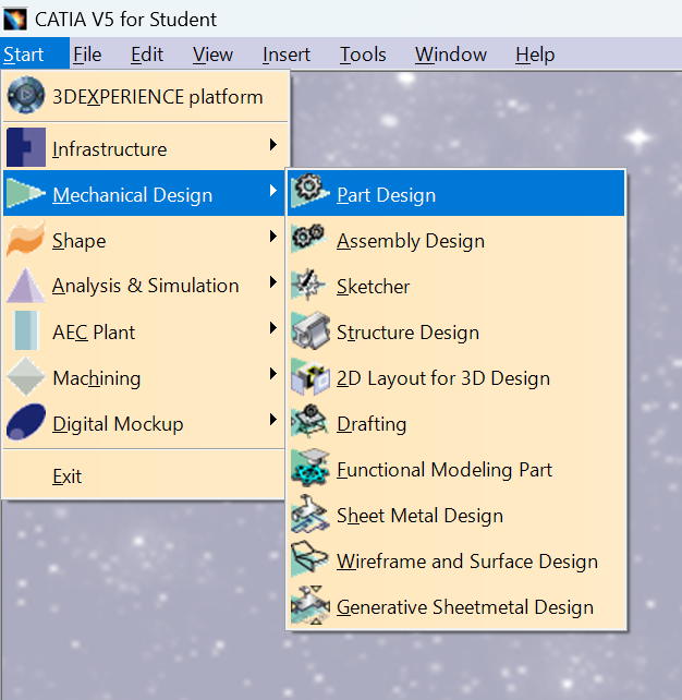
The first thing that appears after opening CATIA is a little menu on the top of the screen, the options for this menu are: Start, File, Edit, View, Insert, Tools, Window, and Help. In order to start a new model I selected Start. After that another menu will appear, this time with different options for modeling and 3D simulations, I selected the option 'Mechanical Design'. This will open another menu with options for mechanical design, I selected 'Part Design' which opened up the 3D modeling space.
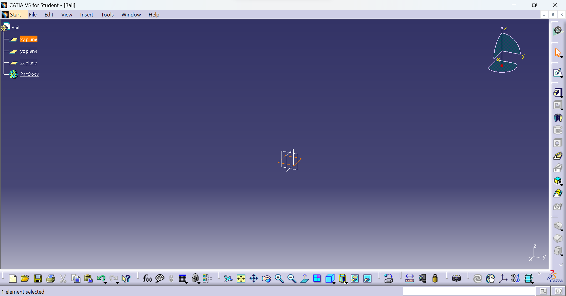
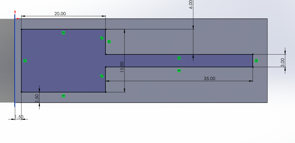
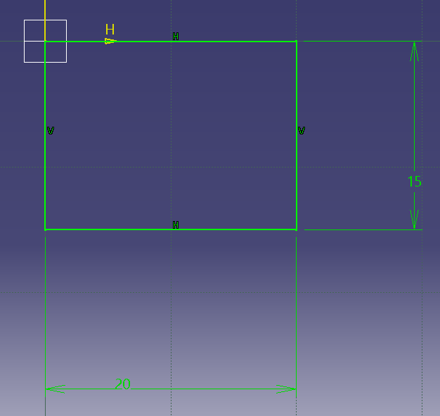
Similar to Solid Works, in order to start a drawing I selected a plane, the toolbars in CATIA are different from the ones in Solid Works, some toolbars may be hidden or even deactivated and it can be a little hard to find some tools. There are lines and geometrical tools generators, constrain which a tool to control de length of what you draw, amongst other options. In my case, I only needed to generate a rectangle and adjust the length of the base and height.
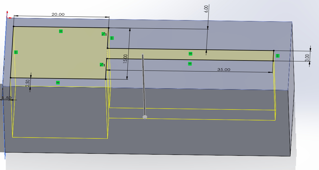
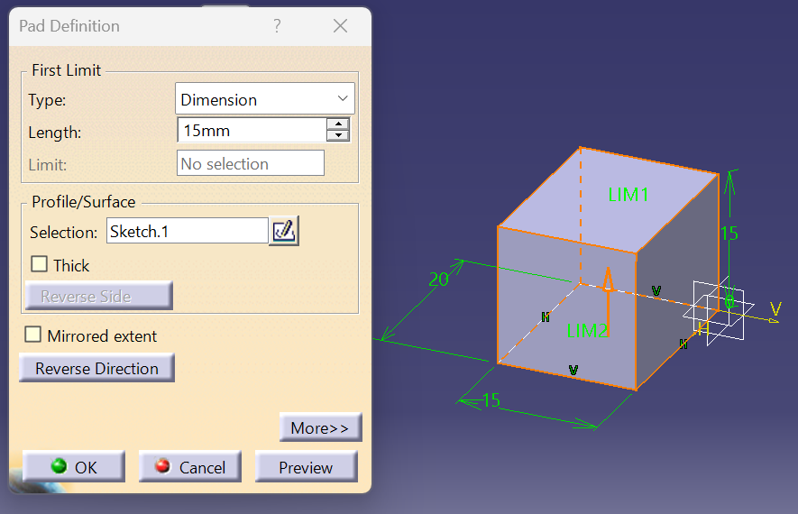
Once the sketch was done the next step was to apply volume, in CATIA the tool that does that is called Pad, it controls the direction and height of the volume.
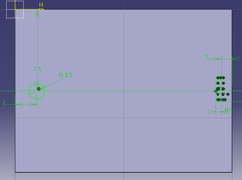
Similar to Solid Works, here I can select a face of the part that I'm modeling to create a new sketch. The sketch was done the same as the first one. After that was done I needed to give depth to those sketches so they would go into the modeled part, in CATIA the tool that help's with that is called Pocket. I found a small problem with this, CATIA didn't let me individually modify different parts that originated from the same sketch so I ended up making two sketches so I could give different depths to my "holes".
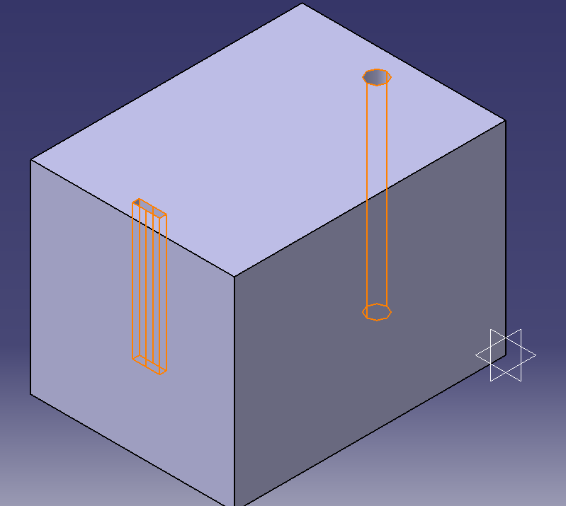
Final CATIA 3D MODEL
Modeling in AutoCAD
The last program I tried was AutoCAD, a 2D modeling software. AutoCAD was the only program I hadn't used, I usually focused more on 3D design in order to print parts for projects so this was a new field for me.
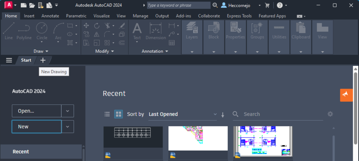
The program opens up a standard menu in which you can open files, create new drawings, or search templates for new projects.
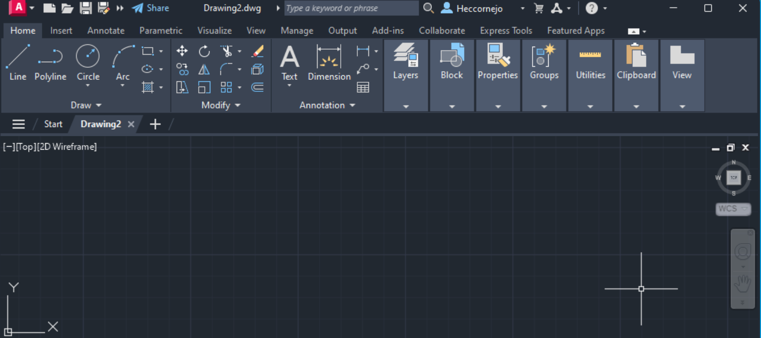
Once I selected the option to create a drawing, a new interface came up with the basic components to create geometrical figures and lines, measure dimensions, and other tools that most modeling software sheare.
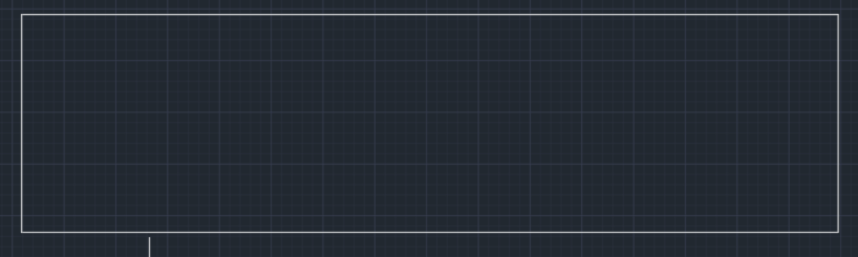
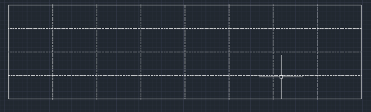
I made a rectangle using the "Rectangle" tool on the toolbar, after that I fixed it's dimensions using the "Dimension" tool.
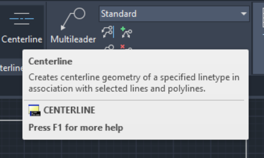
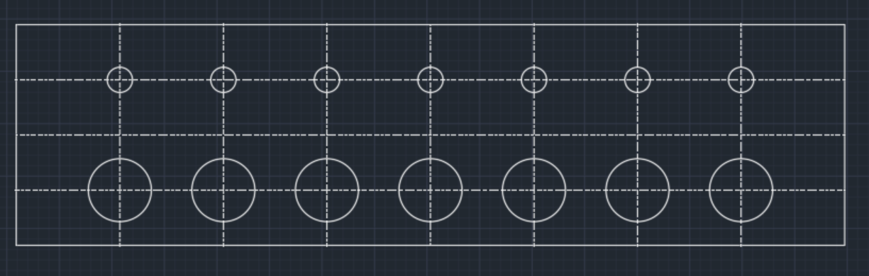
This drawing is a simulation of a base for my final project. In my design, I needed it to have holes. The first thing I needed to make them was a reference in order to create them symmetrical between them. I found a tool called "Centerline", this tool creates centerline geometry associated with selected lines.
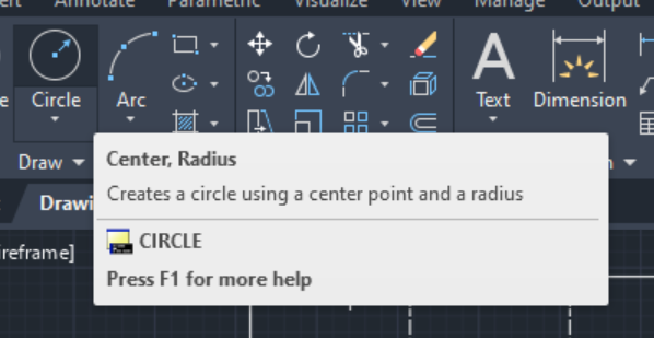
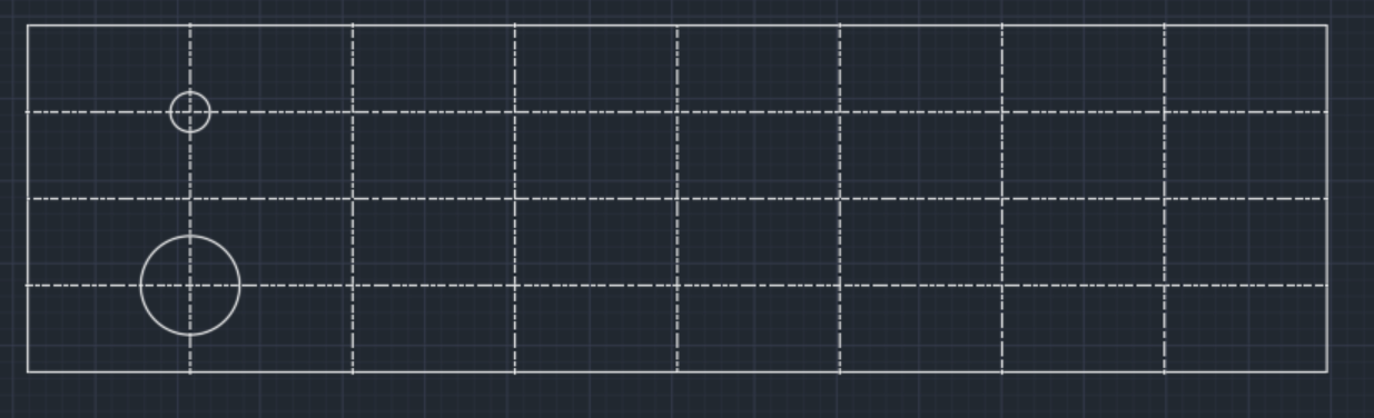
Once I had my rectangle divided I needed to add my circles. There are a variety of ways to make them, in my case I used the "Center, Radius" tool. That tool allows the user to select a point that will be the center of the circle after that I just had to adjust the radius of the circle.
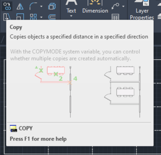
Finally, I just needed to copy that pattern in the rest of the center lines. Having experience with other modeling softwares I imagined there would be a way to copy those circles into the center lines, and after searching in the toolbar I found the "Copy" tool. This tool lets the user copy an object at a specified distance in a specified direction.
Conclusion
Now that I had the opportunity to play around a little bit with a comparison between AutoCAD, Solid Works, and CATIA I ended up leaning toward Solid Works. In the process of making each part in the three different software, I found that Solid is what I would call user-friendly. In Solid, you can find all the tools in the same menu display but in CATIA some tools are "hidden", as for AutoCAD even though is somewhat simple to use I don't really see the use on a 2D modeling software for my project. Another advantage that Solid has over CATIA is that if you put the marker over one of the tools it displays a small sign that briefly explains what it does and how you can apply it. Both programs share the same basic operations but Solid Works does better work when it comes to simplifying the process of 3D modeling.