5. 3d Scanning and printing
3D printing
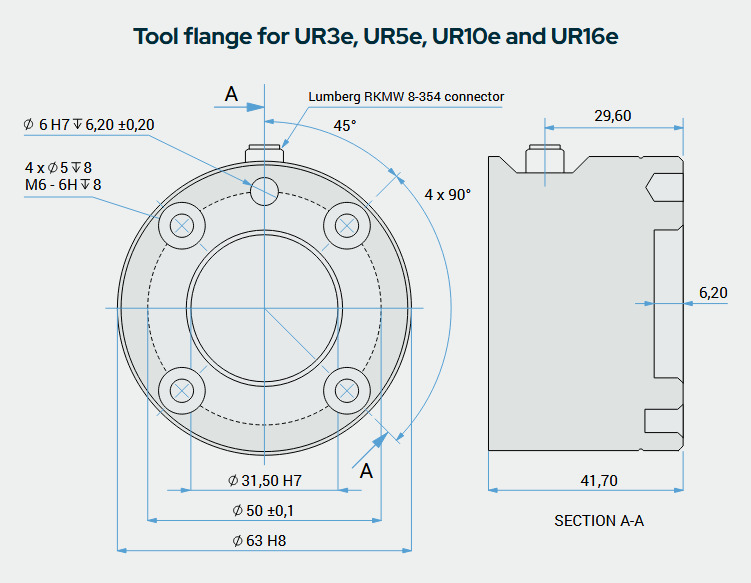
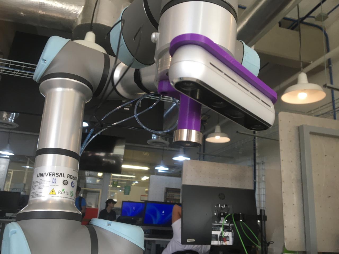
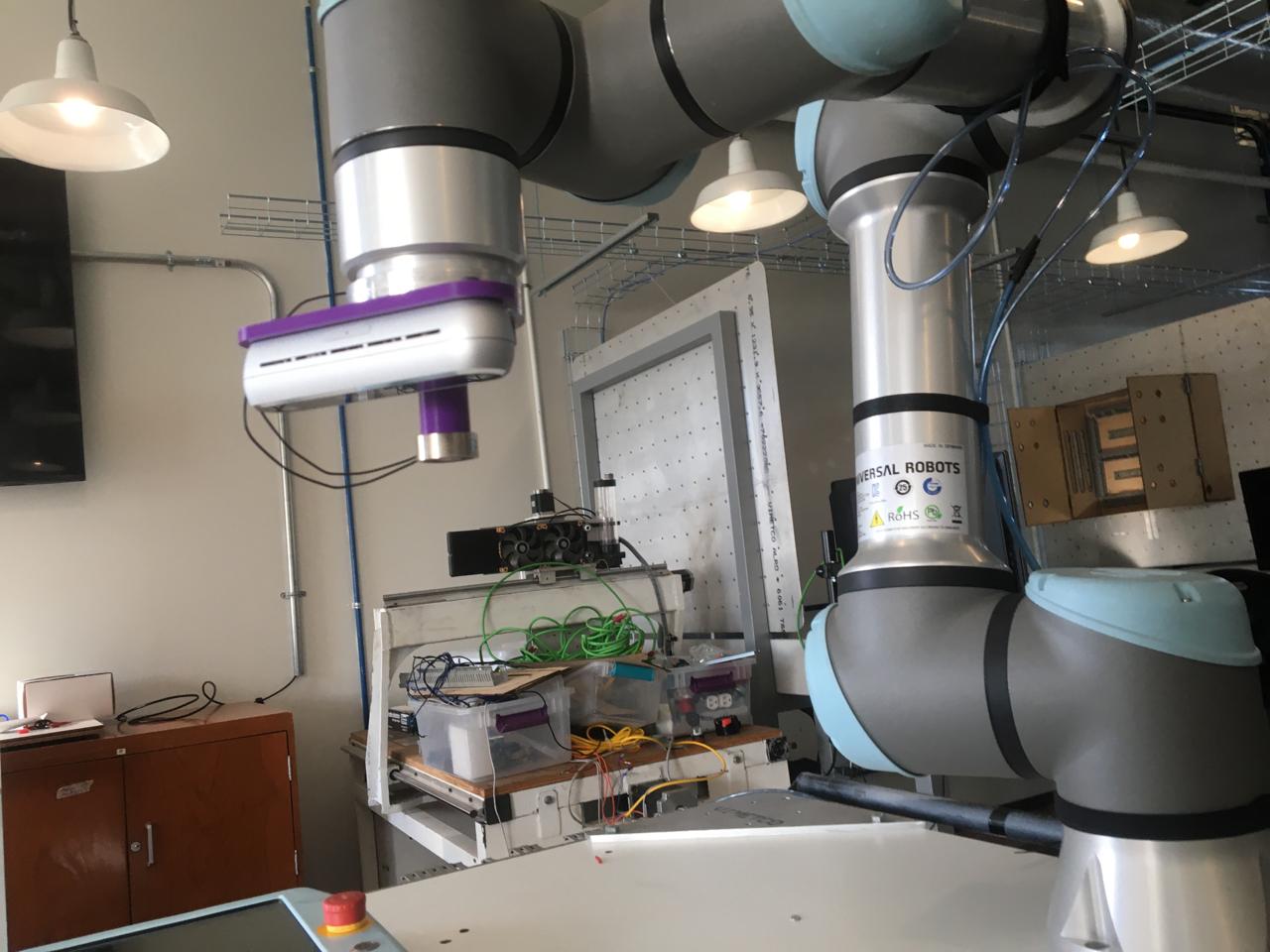
This is an UR5e it's a collaborative robot developped by Universal Robots, here at Ibero Puebla we have one of this and for my AI project, that you can see at my about me page, my team and I want to use it to make a vision based pick and place robot for surgery assitance.

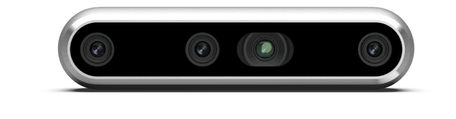
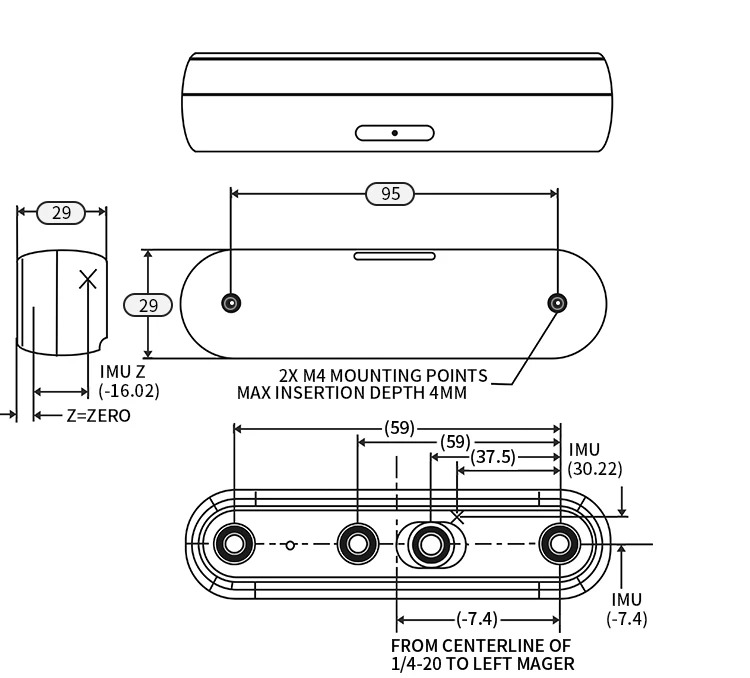
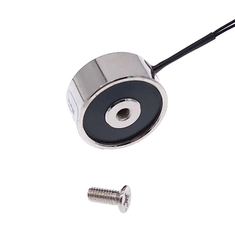
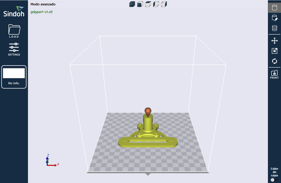
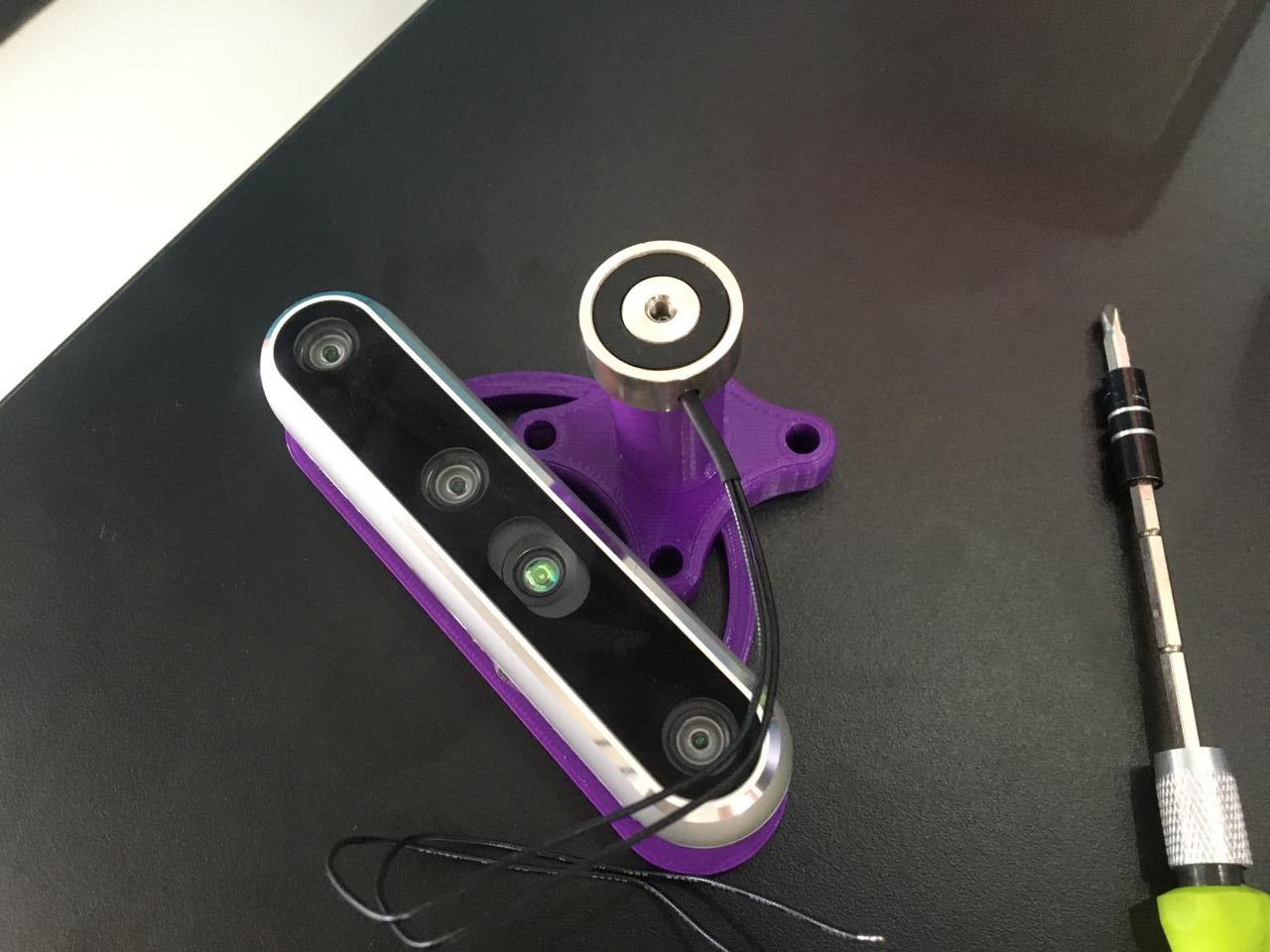
This robot will be used to assist doctors as a scrub nurse in surgeries, so we are using an electromagnet to pick up the surgical instruments and a depth camera (Intel realsense D455) to use the previously developped AI algorithm. So I had to develop a gripper that hold both the electromagnet and the camera and be placed on the robot, for this application it must be ressitant and vibrations should not affect the camera.
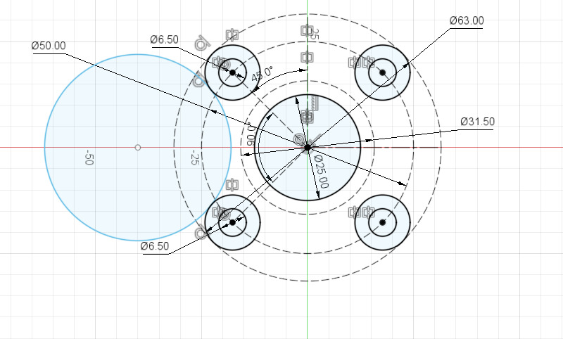
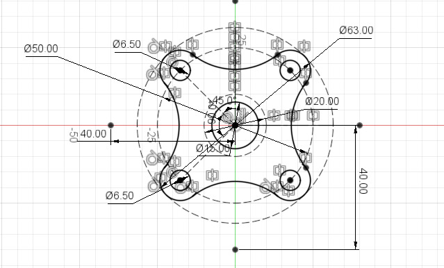
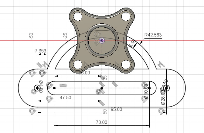
I used the schematics of the robot to find the meassurments for the screw placement that my gripper needed and also the schematics for the camera in order to attach it properly to the gripper. As I would be ussing M4 and M6 screws I required a guide on how to properly make the hole size so the screws fitted perfectly without the need to adjust the holes after it was printed, for that I used our group assignment page: Week 5 Guide Ibero Puebla Fablab. This model cannot be done with a milling machine because of the depth of some parts, the quill would crash trying to do some of the holes, too much material would be used because you would need a piece of about 10x8x6 cm, and it would have to be milled on two superfices to be made.
First, I made the design in Fusion 360, I started with the base that would be attached to the robot, then I added the support for the electromagnet and finally the one for the camera.
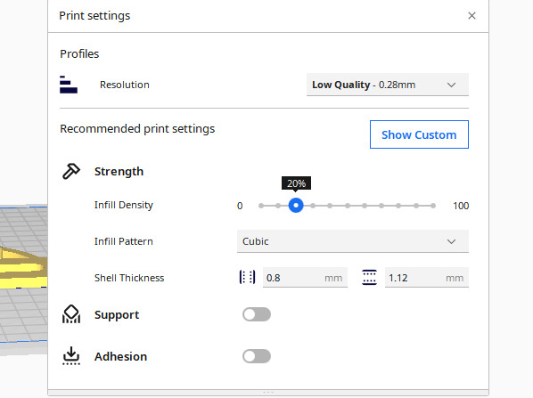
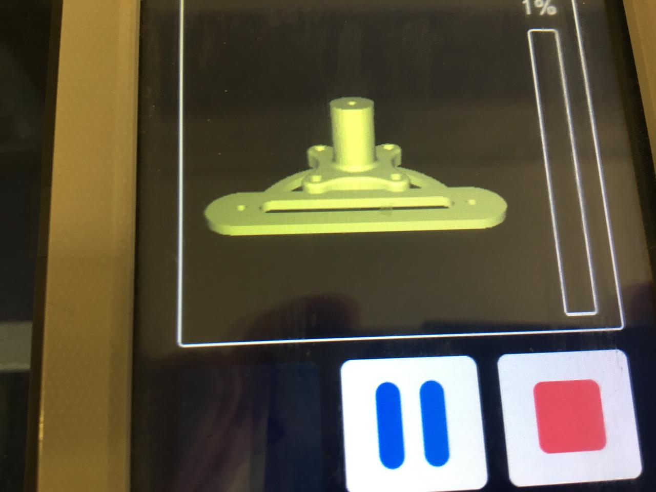
I wanted to test the quality and speed of the 3d printers that we have at our fablab so I printed two of this models, one in a 3dwox1 (black PLA) and the other on an Ender 3 Pro (purple PLA). I downloaded both softwares for the printers, selected the corresponding model of the printers, then I exported the files and placed them properly so the printer had an easier (and faster) time with the prints, I lowered the quality so the lines were a little thicker to print it even faster. Both printers took between two and a half to three our to print, I think the 3dwox1 was a little faster.
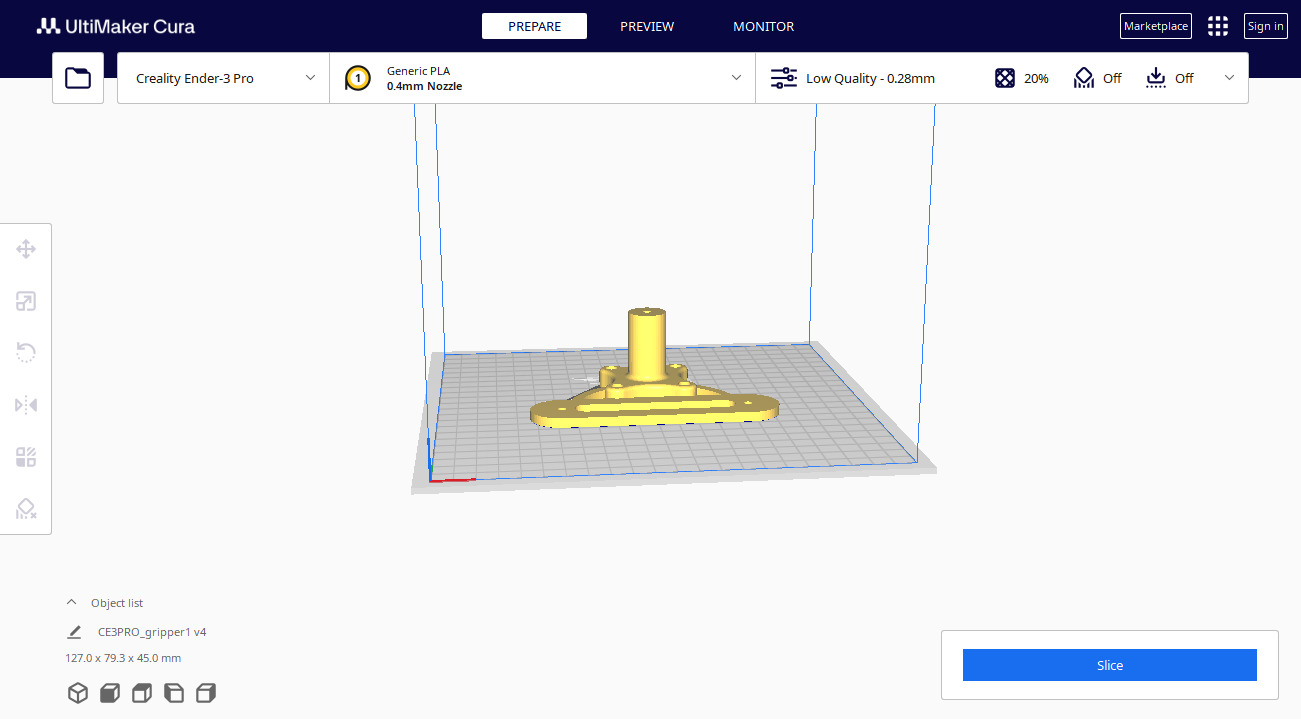
Then I generated and saved the G-code files with the slice command on both softwares, after that I just uploaded the generated files onto the respective drives (an USB thumbnail for the 3dwox1 and an SD card for the Ender 3 Pro).
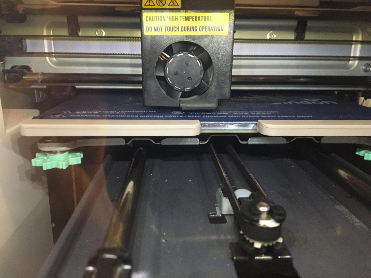
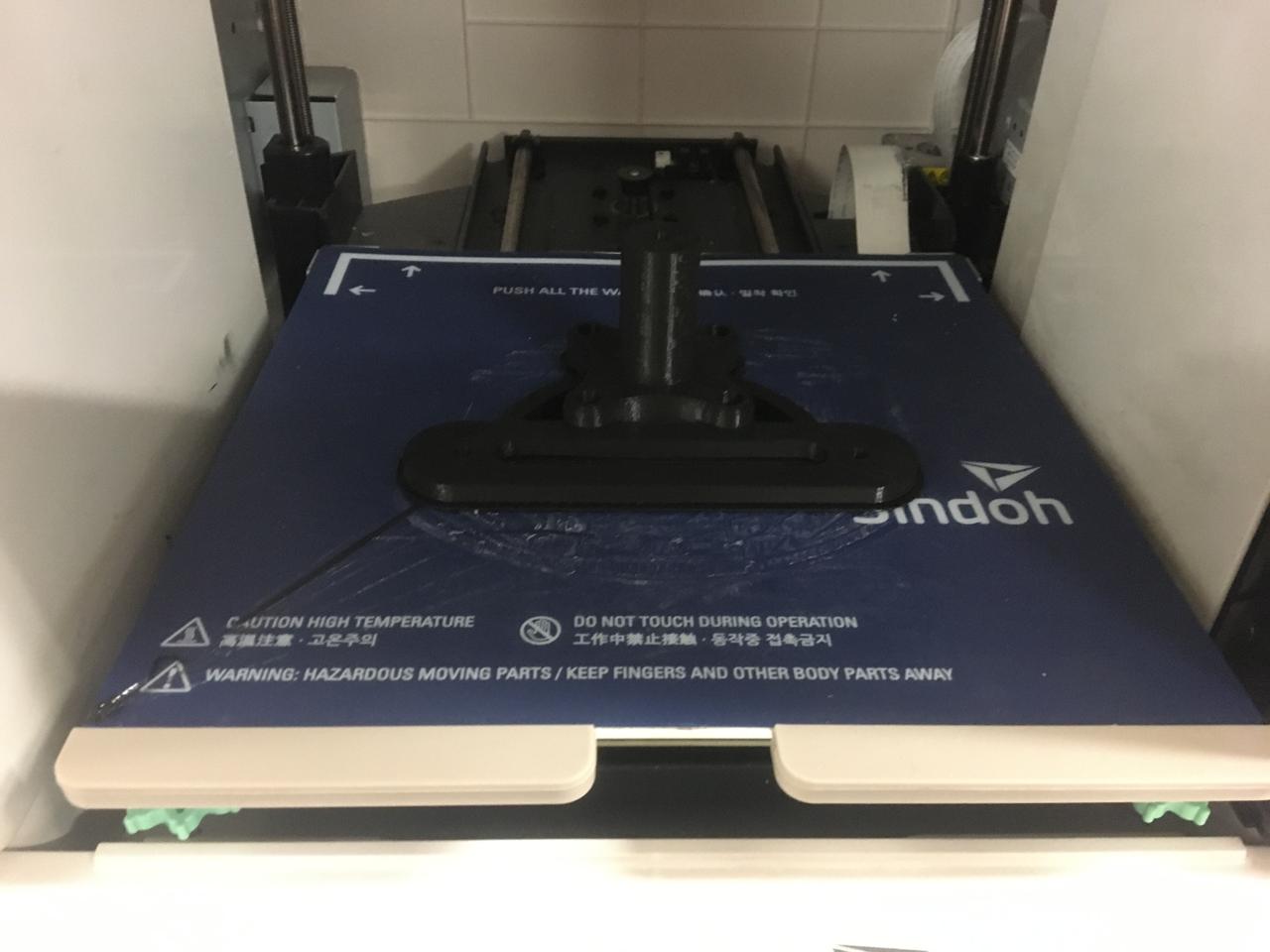
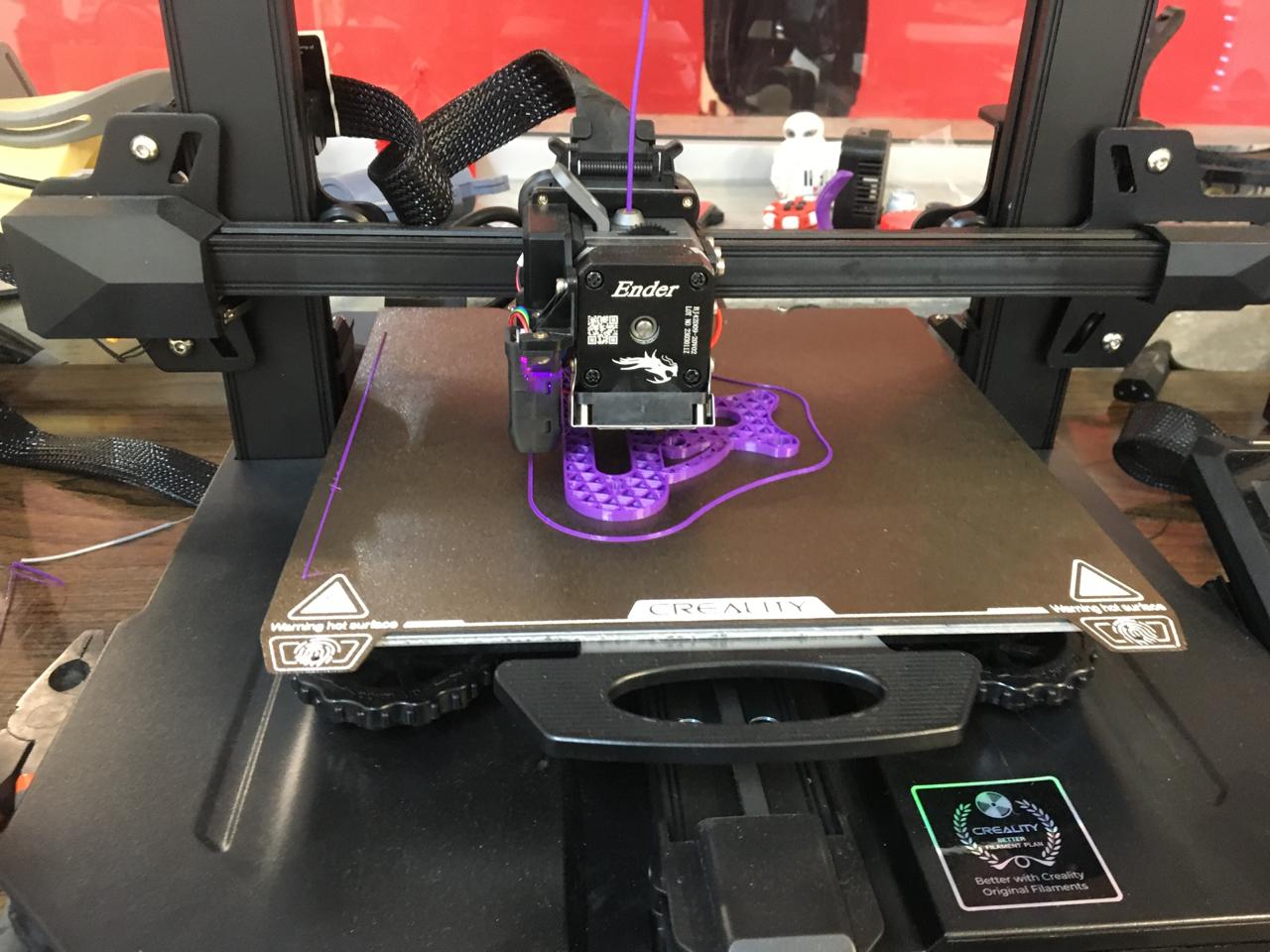
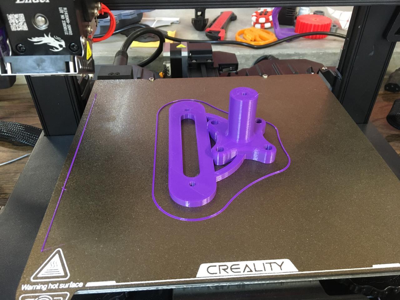
After they finished printing I took them out of the heat beds of the printers, I only had to remove excess from the one I printed on the 3dwox1 and the quality was lower than the one on the Ender 3. On neither of them I had to use supports for the inside because the bridge wasn't that long.
Here's a comparission table between both printers I used but consider that the 3dwox where purchased about 10 years ago and the Ender 3 Pro has about 2-3 years and that might be why I found the pieces made in the Ender a bit smoother, I suffer from asthma and I can't use the resin one.
 |
 |
|
|---|---|---|
| Feature | Ender 3 Pro | 3DWOX 1 |
| Build Volume | 220 x 220 x 250 mm | 210 x 200 x 195 mm |
| Build Surface | Heated bed with BuildTak-like surface | Flexible Metal Bed |
| Filament Compatibility | PLA, ABS, PETG, TPU, and more | PLA, ABS, Flexible, and more |
| Printing Speed | Up to 180 mm/s | Up to 200 mm/s |
| Layer Resolution | 100-400 microns | 50-400 microns |
| Frame Material | Aluminum | Plastic, Metal |
| Nozzle Diameter | 0.4 mm (replaceable) | 0.4 mm (replaceable) |
| Connectivity | USB, SD Card | USB, Ethernet, Wi-Fi |
| Display | LCD Screen with Knob | Touchscreen LCD |
| Software Compatibility | Cura, Simplify3D, Repetier Host, etc. | XYZmaker, Simplify3D, Cura, XYZware |
| Auto Bed Leveling | Manual | Automatic with built-in sensor |
| Enclosed Chamber | No | Yes |
| Filament Detection | No | Yes |
| Print Recovery | No | Yes |
| Price Range | Lower | Higher |
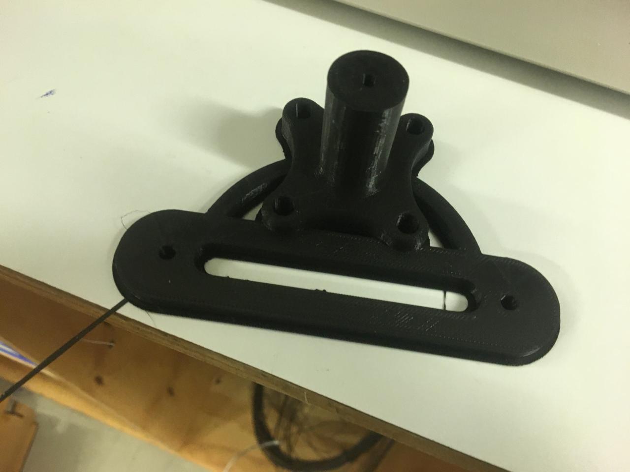
I will be using the purple one because I liked the quality a lot more and on the black one a found a little mistake on the spacing. I gotta say they both have great stiffness. Here are some pictures of everything mounted together.
Also I made this wrist band to try print in place joints, which cant be done with other processes in just one operation.
First I designed the individual pieces, atleast a 0.5 difference between the diameters of the hinge-like joints should be set.
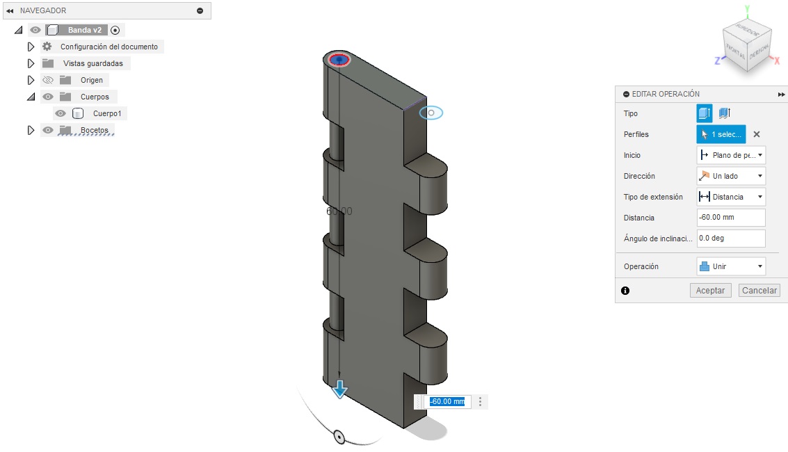
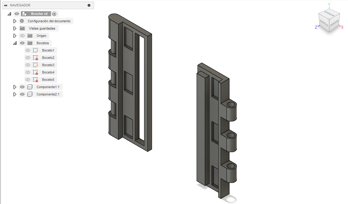
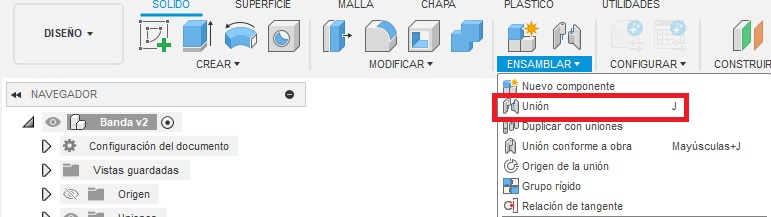
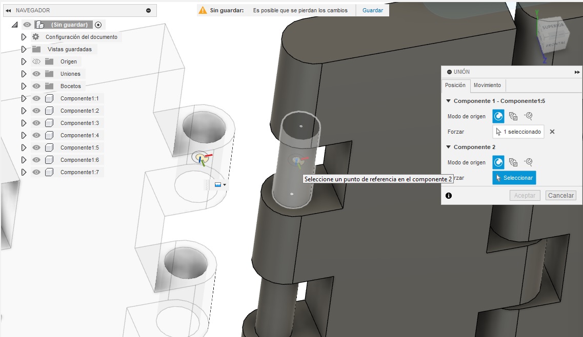
Then I transformed them from objects to components on the left menu. Then I used the joint operation to put them together.
Afterwards I printed it on standar quality. Hoped it work and tested it after it was done.
You can download the step file by clicking here, this type of file will allow you to add or extract components on Fusion360 or SolidWorks, so you can costumize it however you need, to print it just export it on stl.
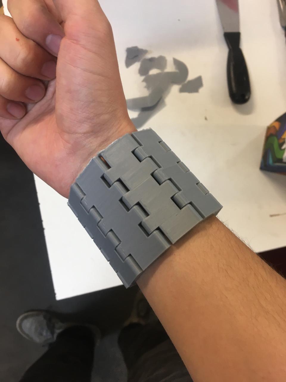
I think it looks really nice and this type of models can be used to make many things like conveyor belts in a single operation.
3d Scanning
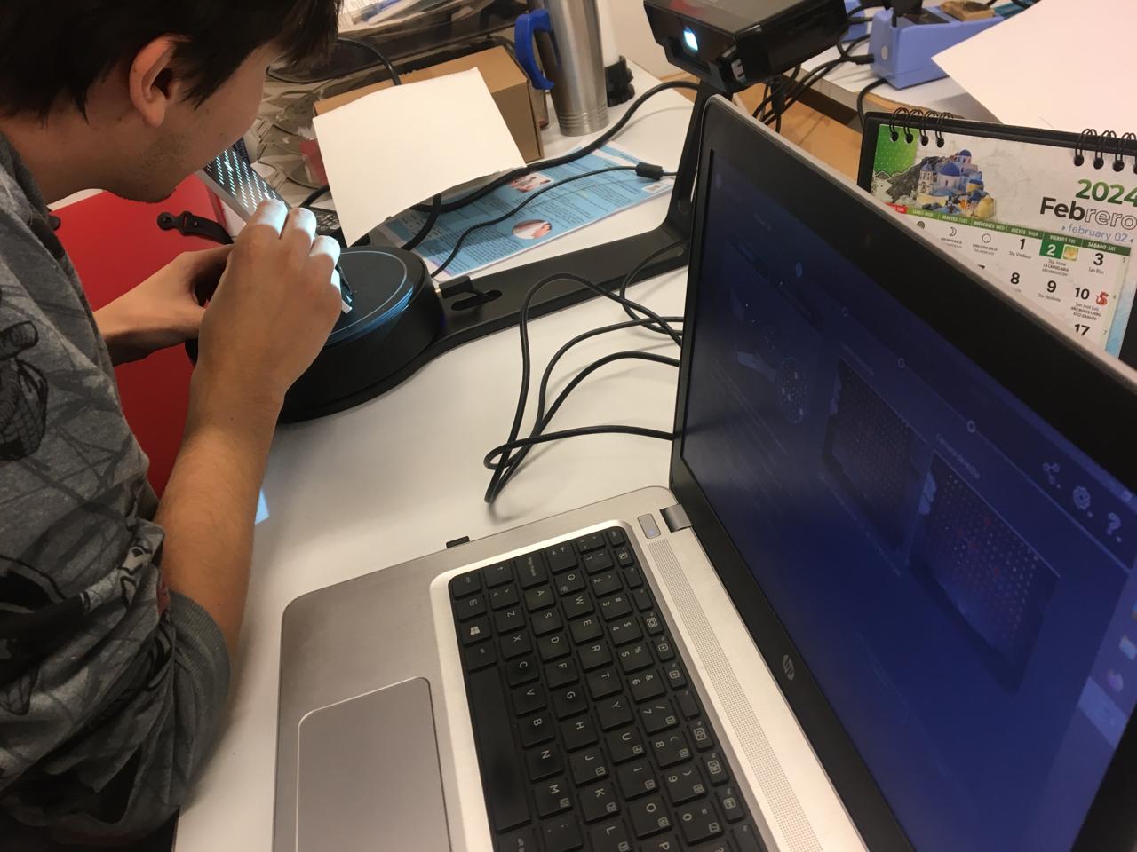
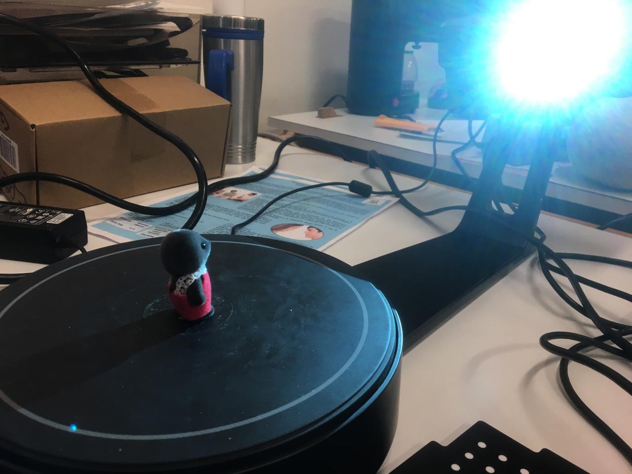
For the 3d Scanning section we used an EinScan-SE and it's respective software EXScan_S. First I plugged the scanner to my computer and the software detected it automatically, once there the machine must be calibrated, to do this the scanner comes with sort of tripode and a sheet of plastic with dots, in this proces the sheet of paper must be seen in it's entirety or as much as possible on the cameras of the scanner which are displayed in the software.
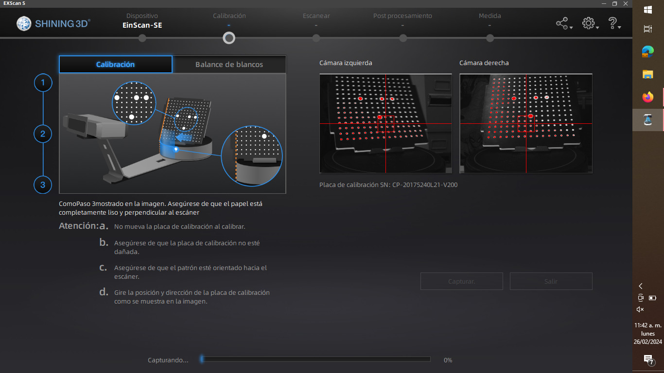
For the calibration process the plastic sheet must be rotated three times as it will be indicated on the software, then the gray scale must also be calibrated.
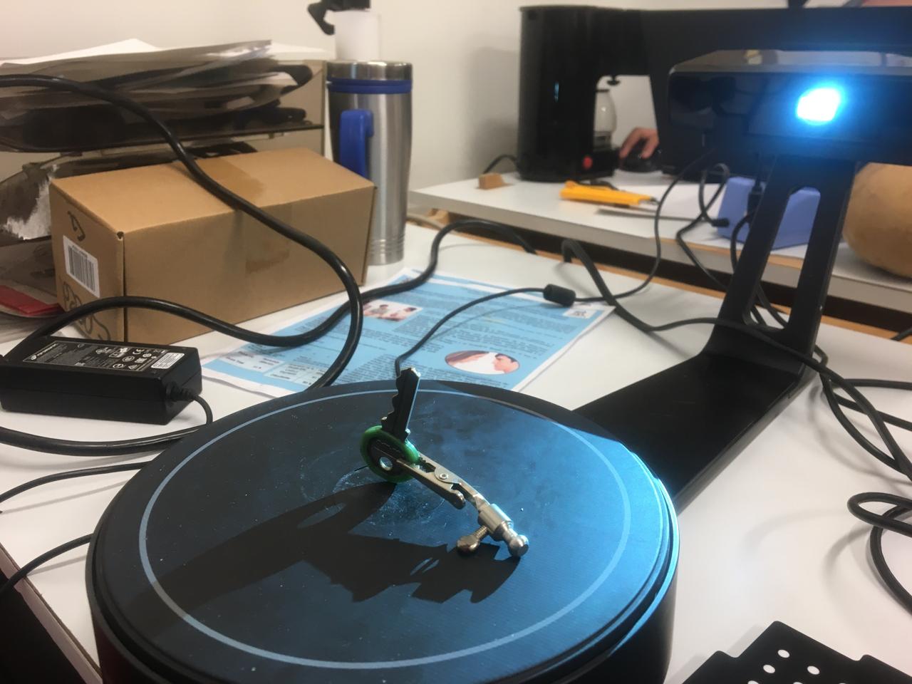
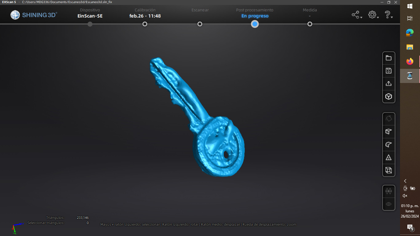
After the calibration process is finished we can start scanning what we want but some considerations must be taken into account, for example I wanted to make a 3d scan of a key which is made with metal, as it's a shinning material, thin powder like make up, magnesia or foot powder should be sprinkled on the piece so the scanner can be more precise, this is because light is shot from the scanner to the piece and sensors detect the photons that bounce back to make the 3d model.
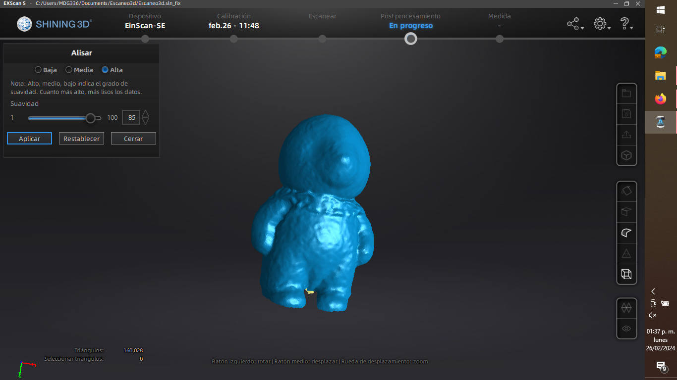
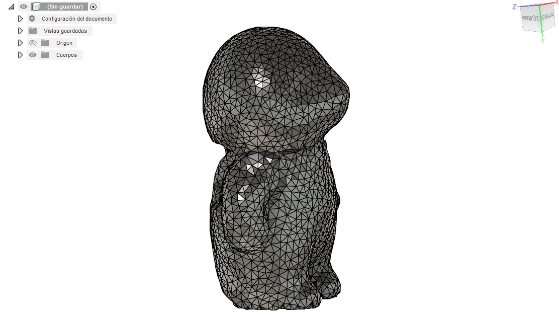
I also scanned this little toy mole, it has velvet so I tought the scanner wouldn't scan it with much detail but it did, I just had to use the smooth operation in the post processing to make it look better, cause it had a very good definition and looked kinda wierd.
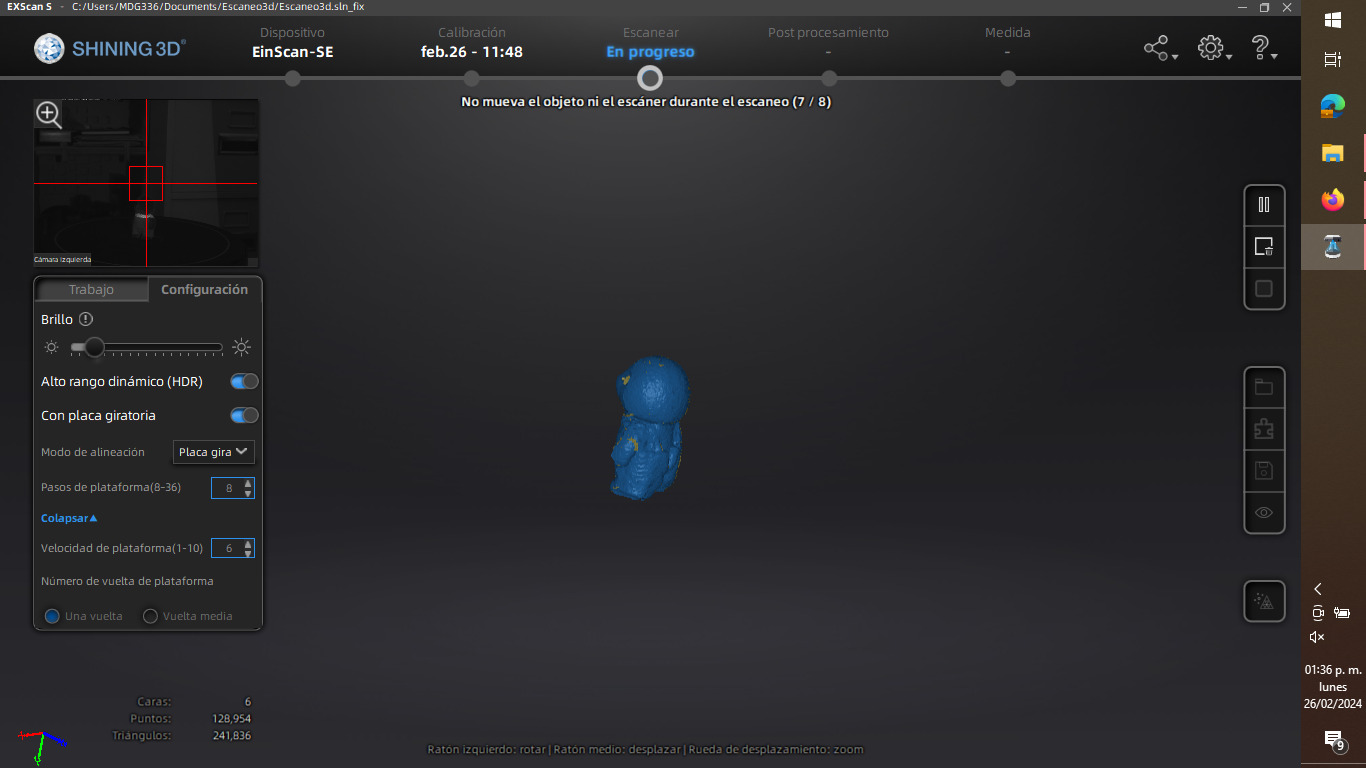
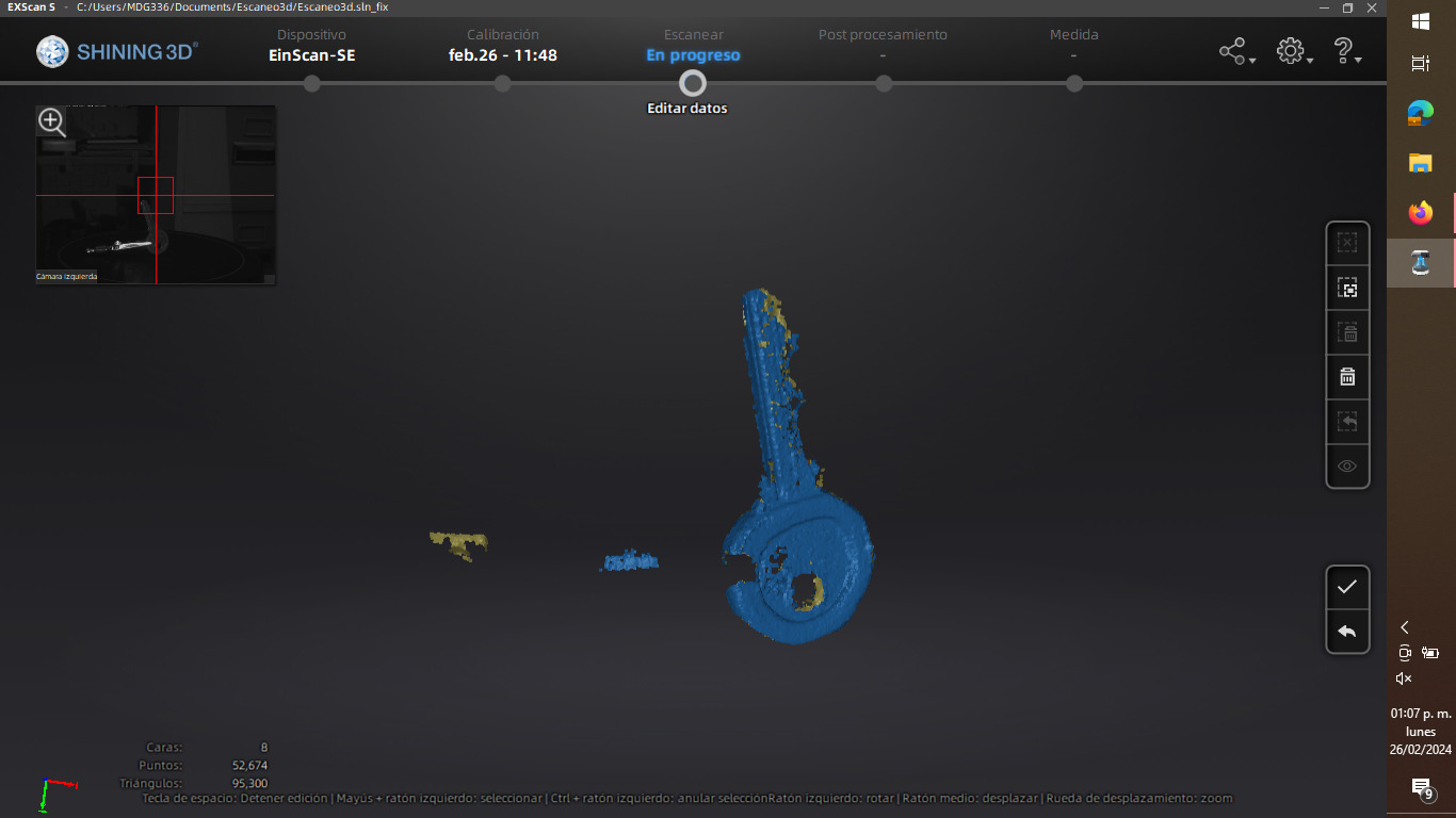
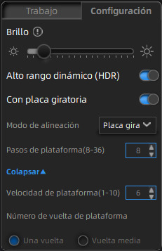
For this process the path that is mostly followed is: Scan > Apply Edition > Global Optimization > Mesh Model > Mesh Selection and detail. In most cases I use the medium mesh to make the file not so heavy, and sometimes to make the scanned object look better details must be added. These were the settings I worked with, the HDR is particularly useful with shinning objects.
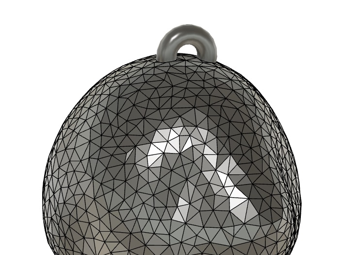
When the scan is first imported and saved in .stl it can look a little weird, because some angles are not scanned, like this:

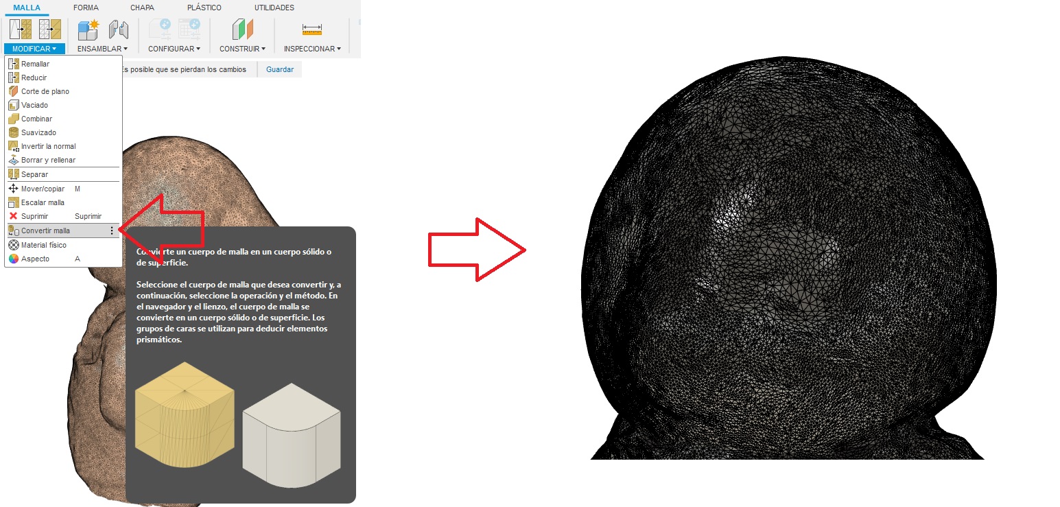
So some post processing should be done. First after opening our .stl in Fusion 360 click on Mesh > Modify > Convert Mesh > Accept. This will turn the stl file from a mesh to an editable object, I think Fusion is the only program that allows this.
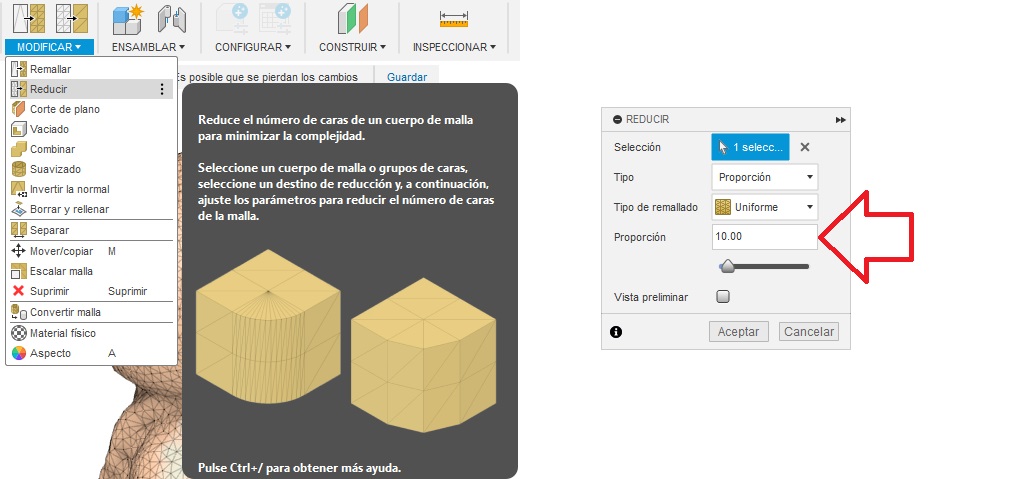
Optionally if your new body has too many polygons like in this case, you can reduce them on the mesh options and do the convertion again. On this operation you have to determine the proportion in which you want to reduce the polygons, 10 works really good.
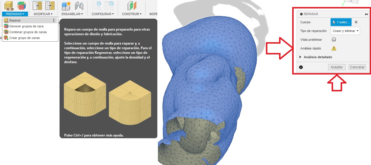
You will end up with a body with less polygons, that is very desirable for either editing from a surface and in some cases 3d printing. Also to close any gaps your scanning may have go to repair, then select your mesh and Fusion will automatically detect the problems and fix them.
Finally your model should look like this. You can download this one by clicking here.
Now it works just as any model made on this software and you can make anything with it, for example in this case i selected a face and made a circle, used the revolute operation to turn it into a key chain.