2. Computer aided design
The assignment this week was to test different softwares for 3D modeling. To evaluate them, I decided to set criteria based on different parameters, that you may find below in a chart. It is also important to mention that I couldn't get all of the softwares in the same computer, since the requirements were more demanding for some programs than others and I didn't want to risk the performance. That's why it is also a parameter.
Softwares for 3D Modeling
| Software | License | Parametric | Requirements | How intuitive is it? | Download Links |
|---|---|---|---|---|---|
| Fusion 360 | Educational | Yes | 4 GB RAM | 75% It has descriptions of tools and feels similar to Inventor. | Download Fusion |
| Blender | Free | With some tools | 8 GB RAM | 10% You really need a tutorial as a beginner. A very different modeling style. | Download Blender |
| Solid Works | Educational | Yes | 16+ GB RAM | 60% It works as other CAD softwares and lets you track the operations you do on the side bar. | Download Solid Works |
---- Fusion 360 ----
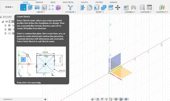
- I started by opening the program and selecting the tool that says “Create Sketch”, it allowed me to choose a face to draw, so I picked the front face.
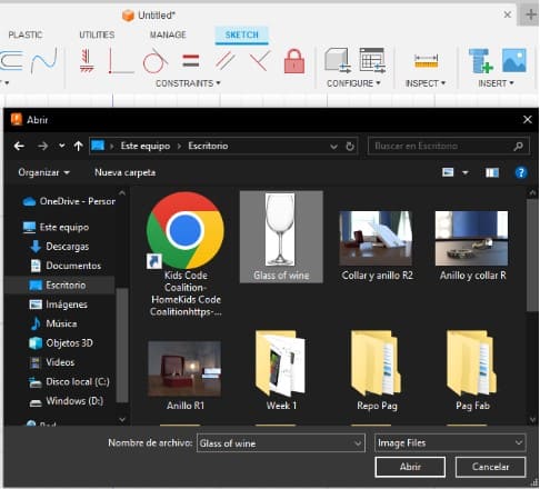
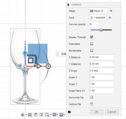
- Next, I Inserted an image for reference from the “Insert” option, choosing the one with the picture, that's called “Canvas”. My picture was called “Glass of wine”.
- Then it let me select the face where I wanted to place my image, and allowed me to edit features like size and position
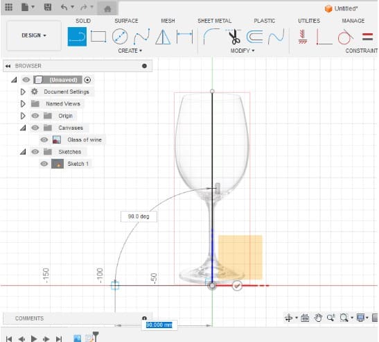
- Once that was set, I double clicked the sketch to be able to edit it. I used the image as a reference, so I would start drawing it's left half, parting from an axis. To draw, I used the "Line" tool, and this allowed me to create connected lines and select their length and angle.
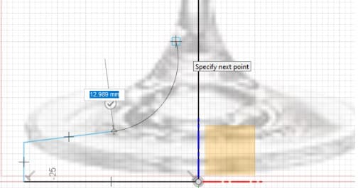
- At this point I discovered that it is possible to turn a straight line into a curve if you drag the end instead of just clicking it. Also, it will make a preview of how round or large you want it to be, even so I only used it for specific curves, not to soften perpendicular unions yet.
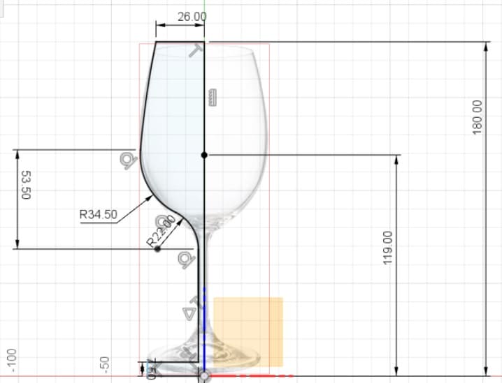
- Once the drawing was complete, it changed color from transparent to a shade of blue, meaning the lines were closed. Then I used the “Dimension” tool, to set the measurements until the lines changed color to black.
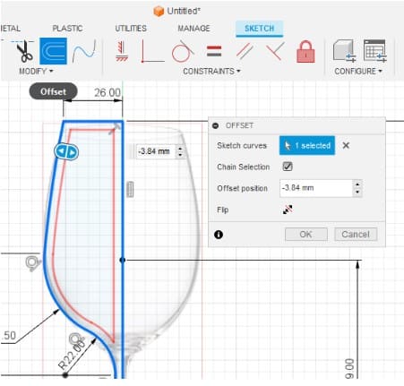
- Then, I used the ”Offset” tool to determine the glass thickness. It made a copy of the original line at a distance, so when I dragged it I could previsualize it.
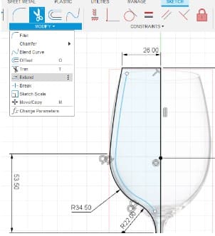
- Right after, I clicked the lines I didn't need and used the tool “Extend” to connect the lines of the offset to the original drawing.
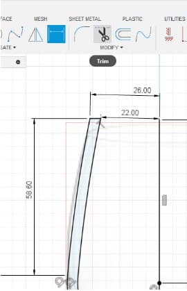
- Then, using the “Trim” tool I kept what would be the solid part of the glass, and dimensioned the drawing again.
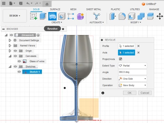
- For the next step, I went out of the drawing and clicked the “Revolve” option. It automatically selected my drawing and asked me for an “Axis” , so I selected the line I drew first.
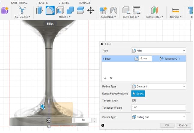
- To soften the edges of the base and the top, I used the tool “Fillet”. It worked by clicking on the edge I wanted and then I played with the measurements to get the roundness I wanted.
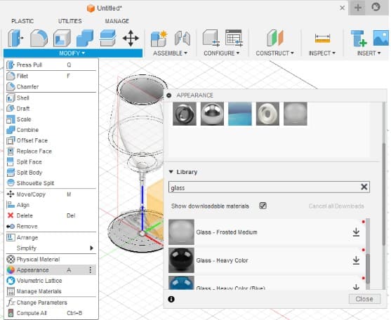
- Finally, I added material to the model, so it would look better. I did this by clicking on the “Appearance” option, then dragged the options to the object to check how would it look like.
- Here it is the final result. I tried to render it, so i changed the menu options from “Design” to “Render” mode. As I had already set a material, the final picture had a more realistic appearance.
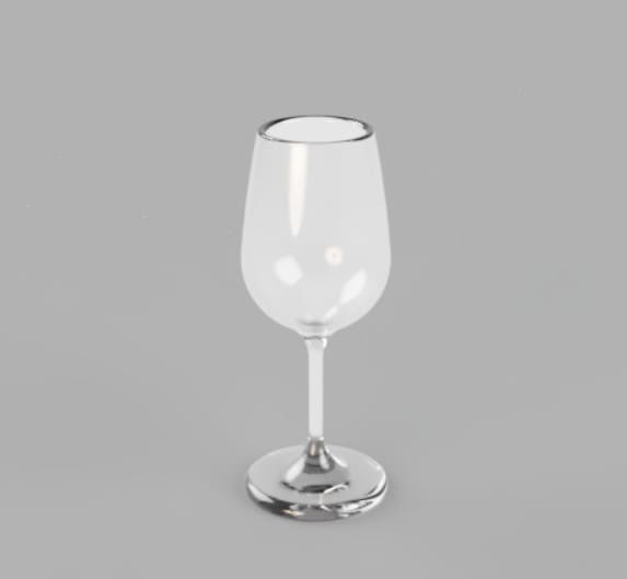
Fusion 3D Model
---- Blender----
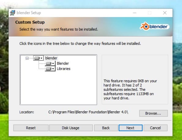
- First, I downloaded it from the website, this is a free software so, the only thing I had to do was to check If my computer had the requirements to support it.
- It went straight to my Downloads folder. There I proceeded to the installation and agreed to the license by clicking on the icon.
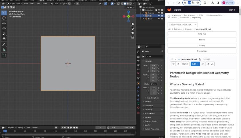
- When the instalation finished, I opened the program to check it out and explore, but I wasn't very familiar to the options and settings, so I followed a step by step guide shared by one of my local professors. This is available on the repository of my Fab, so It's here in case you find it helpful.
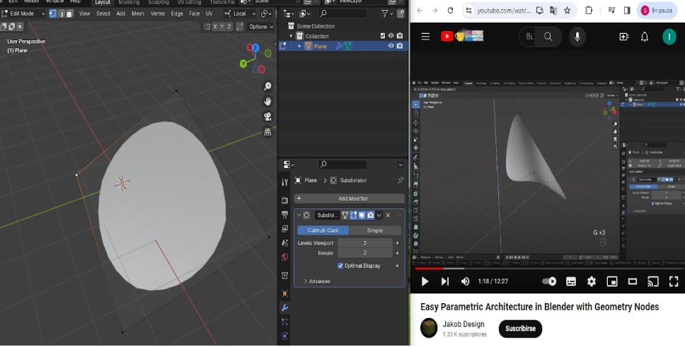
- The site included the explanation about what are the "Nodes", and how they are a key element to work with Blender. I didn't get how to use them quickly so, I worked as I followed a tutorial side by side.You can watch the same video if you open this link.
- I started by creating a shape and deforming it. To add the shape I pressed "Shift + a" , and to deform it I dragged the corners after pressing the G key . I also changed the amount of sections the shape had, so it changed from a square to a more rounded object.
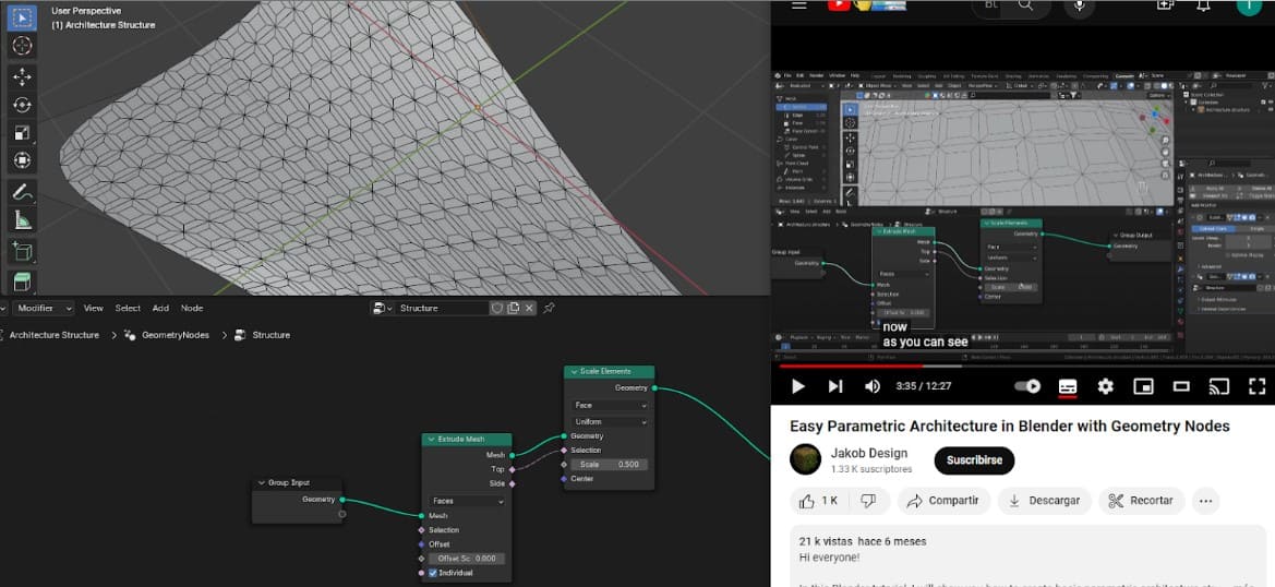
- Once I had deformed the object, I started working with the "Nodes". To do it, I clicked on the "Geometry nodes" option, and then the base nodes appeared.
- Next, I kept inserting different nodes to transform the original shape:
- The "Extrude Mesh" node to give some volume.
- The "Scale elements" node to modify the and to deform the mesh.
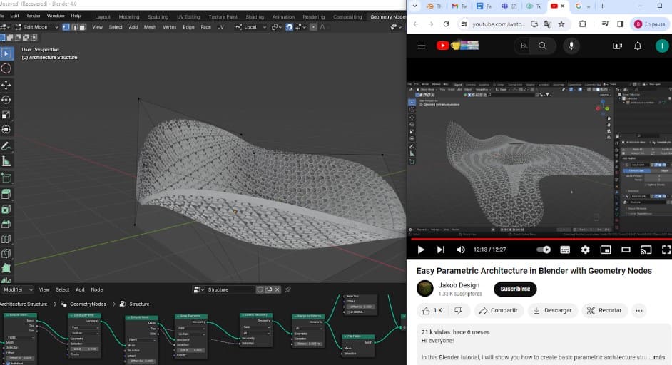
- The "Delete Geometry" node to remove some faces and make it hollow.
- The "Flip Faces" node to change the direction of the surfaces and keep it smooth.
- The "Merge by Distance" node to join surfaces after a given distance.
- Finally, when I had the nodes linked and a sequence to transform the original model, I saved the file.But It was too heavy, so to compress it I followed a tutorial I found here.

Blender 3D Model
---- Solid Works ----
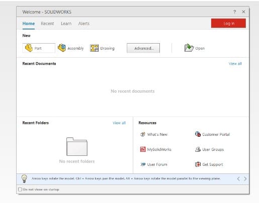
- First I opened Solid and Chose the option to “Create Part
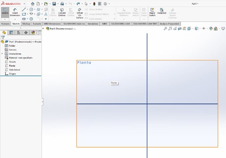
- As I did with Fusion, I created a sketch on the top plane , this feature appeared in spanish it said “planta”.
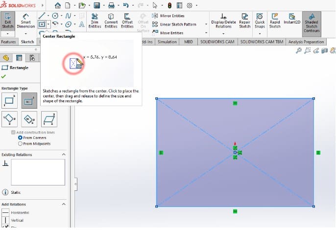
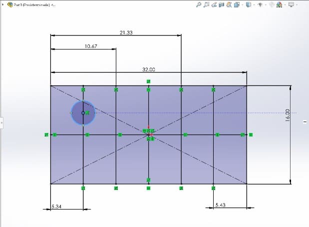
- To work with solid I started by choosing an interesting design, I chose to make a Lego brick. So the first thing I drew was a rectangle with the tool “Rectangle from the Center”.
- I gave it dimensions next, and also added six lines inside as reference. It is possible make operations inside of the dimension box if you don't know the exact measurement but you have some references.

- Right after, I subdivided the element into sections and drew a circle that I would use as a reference.
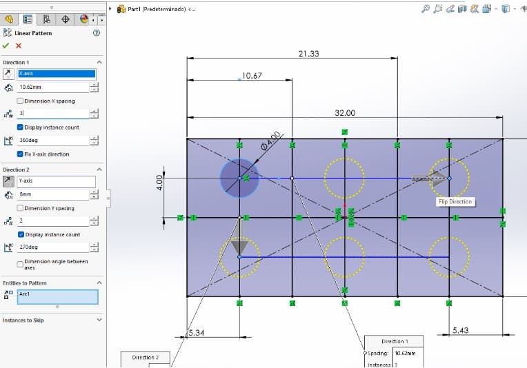
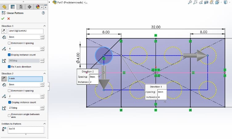
- Once i had this circle, I replicated it with the tool “Linear Sketch Pattern” that helped me to reproduce the circle five more times and fix it to it's place.
- Then I used the “Extruded boss / Base” option to build the volume of the circles.

- Up to this point, I thought It didn't look good enough, so I decided to change the amount of cylinders I had, from being 6 to 8. This made me go back to build the mesh again.
- After drawing the sketch again I did an "Extrusion" for the cylinders and another for the main body of the brick. It definetly looked better this way.
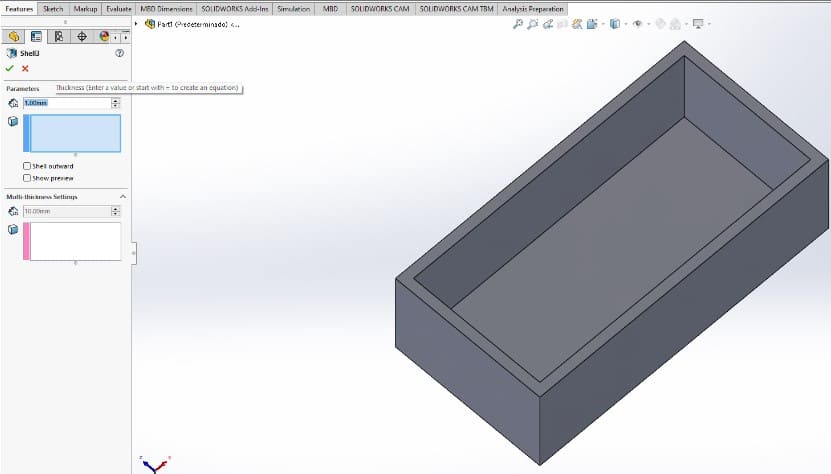
- At this moment, the object was completely solid, so I had to use the "Shell" tool to make the back face hollow as a the real object.
- Once I did, the last change I did was to soften the edges with the tool "Fillet". I took all of the borders exepting the hollowed face and made them slightly rounder.
- Finally, I changed the way the model looked like using the side bar on the right of the document. There I found the "Appearance" tool, where I tested different materials, colors and shapes. As in Fusion, I dragged the options to the object.
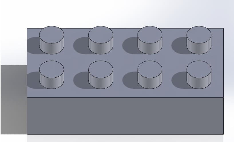
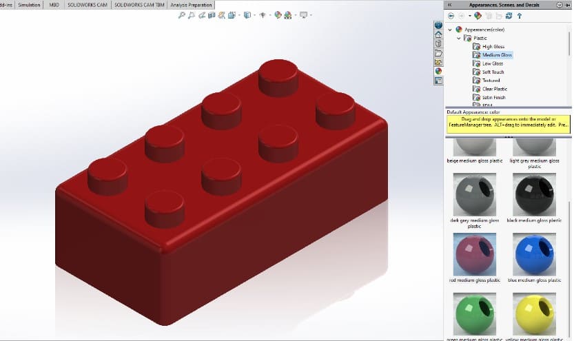
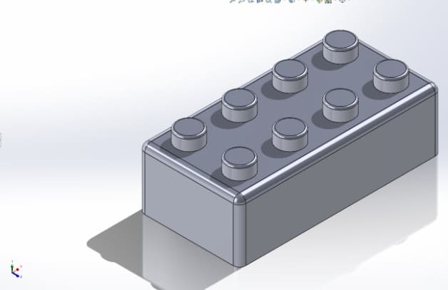
Solid Works 3D Model
---- Blender----
- First, I downloaded it from the website, this is a free software so, the only thing I had to do was to check If my computer had the requirements to support it.
- It went straight to my Downloads folder. There I proceeded to the installation and agreed to the license by clicking on the icon.
- When the instalation finished, I opened the program to check it out and explore, but I wasn't very familiar to the options and settings, so I followed a step by step guide shared by one of my local professors. This is available on the repository of my Fab, so It's here in case you find it helpful.
- The site included the explanation about what are the "Nodes", and how they are a key element to work with Blender. I didn't get how to use them quickly so, I worked as I followed a tutorial side by side.You can watch the same video if you open this link.
- I started by creating a shape and deforming it. To add the shape I pressed "Shift + a" , and to deform it I dragged the corners after pressing the G key . I also changed the amount of sections the shape had, so it changed from a square to a more rounded object.
- Once I had deformed the object, I started working with the "Nodes". To do it, I clicked on the "Geometry nodes" option, and then the base nodes appeared.
- Next, I kept inserting different nodes to transform the original shape:
- The "Extrude Mesh" node to give some volume.
- The "Scale elements" node to modify the and to deform the mesh.
- The "Delete Geometry" node to remove some faces and make it hollow.
- The "Flip Faces" node to change the direction of the surfaces and keep it smooth.
- The "Merge by Distance" node to join surfaces after a given distance.
- Finally, when I had the nodes linked and a sequence to transform the original model, I saved the file.But It was too heavy, so to compress it I followed a tutorial I found here.
Blender 3D Model
---- 2D Modeling: Illustrator ----
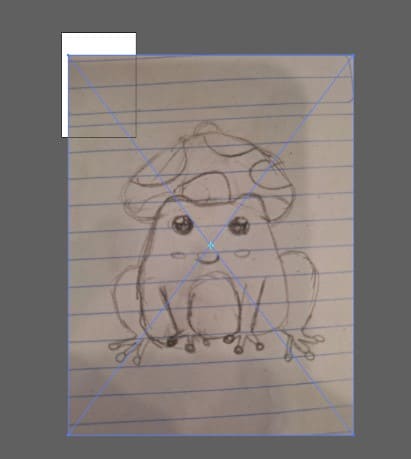
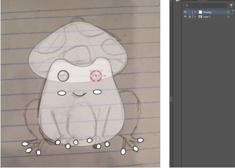
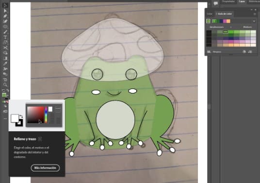
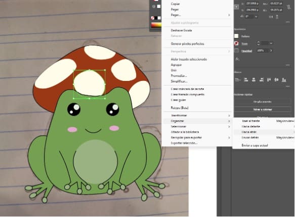
- The first thing I did was to sketch a doodle I wanted to turn into a vector , in my case it was a frog with a mushroom hat.
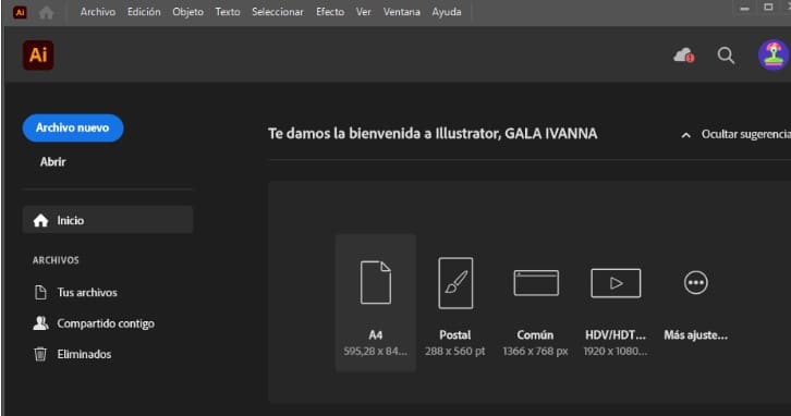
- Once I had it, I took a picture of muy doodle to store it on the computer. Then I opened Illustrator and created a new file size A4.
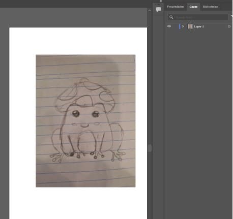
- I opened the doodle archive I had and placed it on the document. I did this by clicking on “File” then “Place”. My image appeared a lot bigger than the worksheet.
- To scale the picture, I dragged it from the corner and held the “Shift” key at the same time to keep the aspect ratio. Up to this point, my drawing was on the first and only layer.