3. Computer controlled cutting
This week I worked with a press-fit construction kit made with the laser cut and and a vinyl cut practice. Here you may find the process divided in steps.
---- The group assignment: The basics of laser cutting ----
To understand better the factors involved with the laser cut, the group assignment consisted in some approaches and tests of the laser performance with different levels of power, speed and materials. Here is a table with some important terms you got to understand to use the laser cutter that we reviewed with the practice, but for further information you may click here .
| Term | Meaning/ Importance |
|---|---|
| Work area | It refers to the space on the cutting table. It's important because restricts the size of the material you want to cut. |
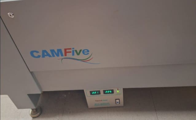
| Machine Power | It indicates the full potential power ot the machine you have. It is provided with watts. The one we have at my Fab is a CAM Five of 100 watts. |
| Laser Power | It indicates the strenght of the laser when it cuts, it's possible to adjust it from the pannel on the program, you may set a "min-max" for your cut, but it is always a percentage of the full power of the laser. |
| Laser Speed | This determines how fast or slow the laser head will move to make the cut. It's important because you combine it with the laser power, so each combination will have different results, for example: if you cut too fast and with little power, the cut will probably remain as an engraving. And if you have too much power and a slow speed you may burn the material. |
| Kerf | It is the name given to the amount of material the laser will vanish when it cuts. The lines of the documents the laser will follow to cut have a "supposed" thickness of 0, but when the laser goes through them, the cuts will have the thickness of it. It is important to calculate it because in the end, the measures in the drawing won't be the same as the finished cut, so it's preferable to give tolerance to the original design, specially if those are pieces for an assembly. |
---- Making a press-fit construction kit: Design Phase----
- Original Piece: "S piece"
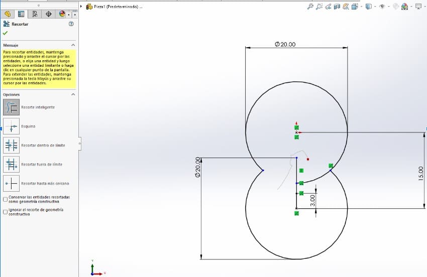
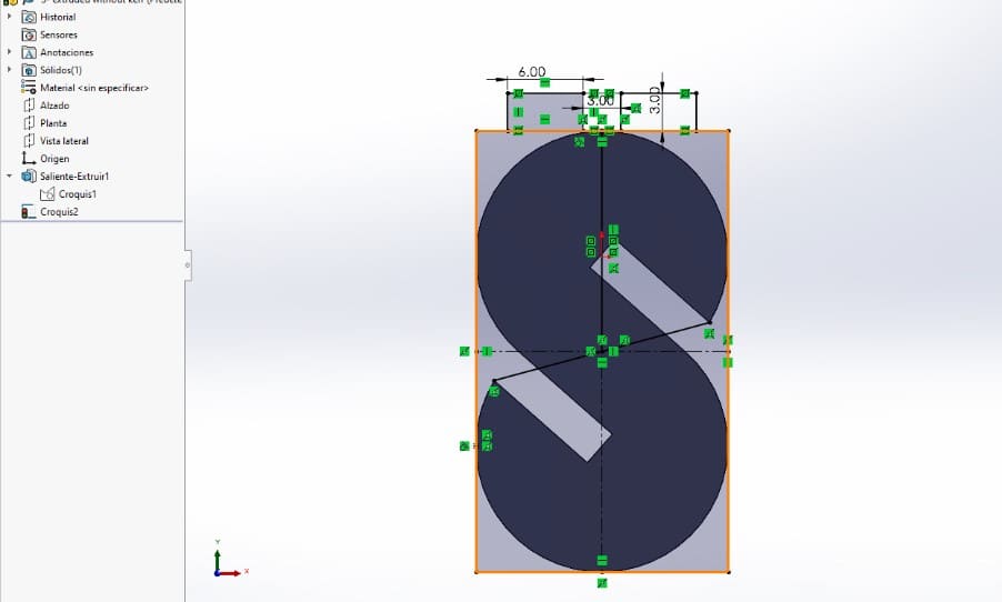
I started by drafting the shapes I thought would allow me to make the kit. My first thoughts were to make something from regular shapes, but the final idea came from how versatile could be to make an s, since it has slots in opposite directions. - To create it the whole project, I worked with Solid Works. There I drew two circles with the same diameter in a new sketch, they were separated by an axis line. Then I defined them and used the “trim” tool to erase the inner lines and connect the shape.
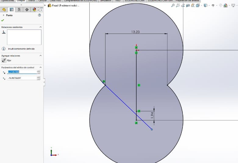
- Then I drew a tangent line from one of the inner vertices. I made the ending point coincident to the axis line I had form the original circle.
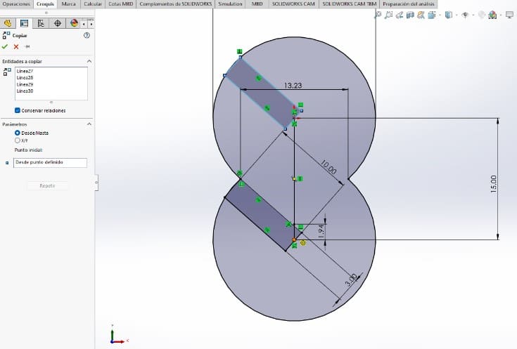
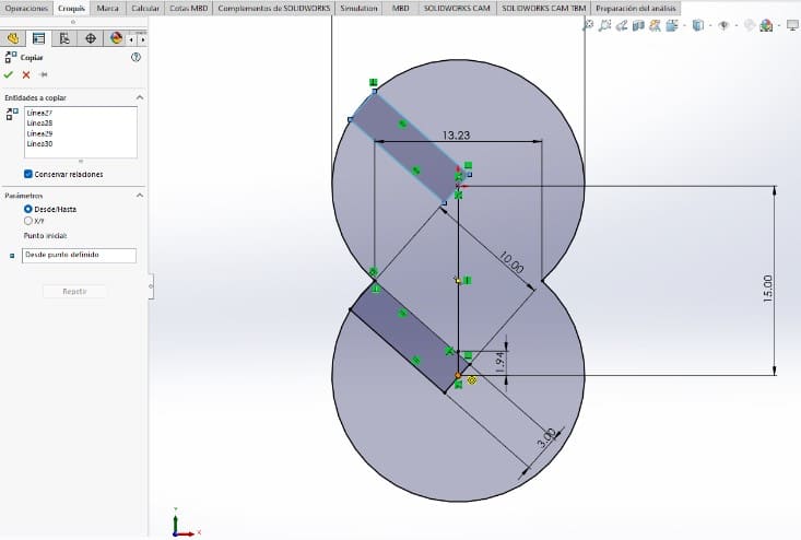
- Following the line, I drew a “three point rectangle” . To define it, I used some sketch relations and gave the rectangle a width of 3 millimeters, (because it was the thickness of the material I would be using). Once it was done, I cloned the rectangle using the “copy” tool.
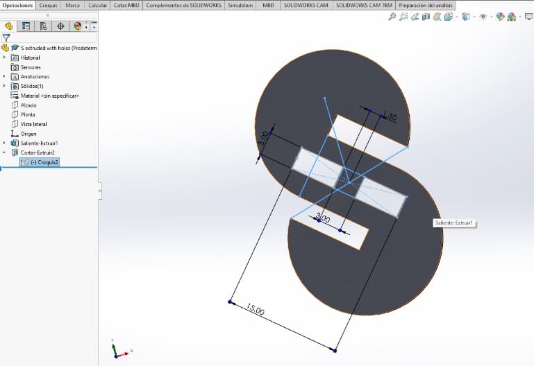
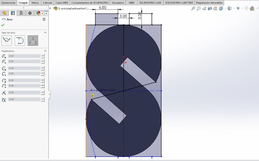
- Next, I used the copy tool again to put it on the opposite side. As my design was supposed to look similar to an S, when I got the rectangles in place, I used the “trim” tool again to cut the exterior edges the shape had.
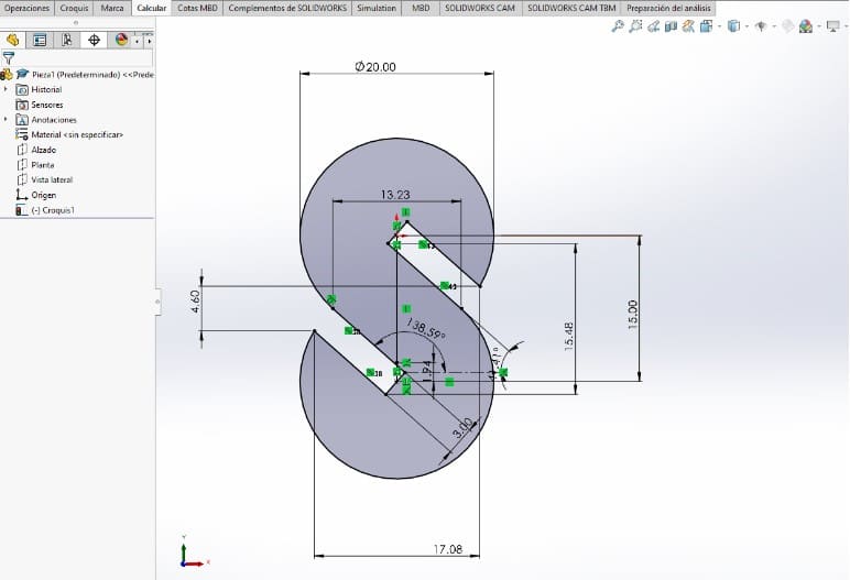
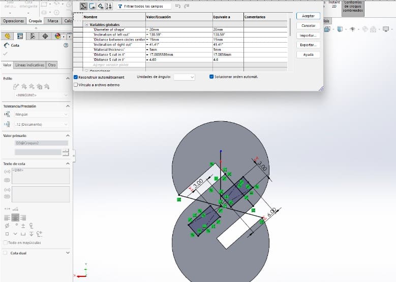
- Once I cut the outer edges, I had to give it more measurements to define it, some I added were: the angle of the slots , distance between the new vertices and distances to a reference point as the origin or the circles axis.
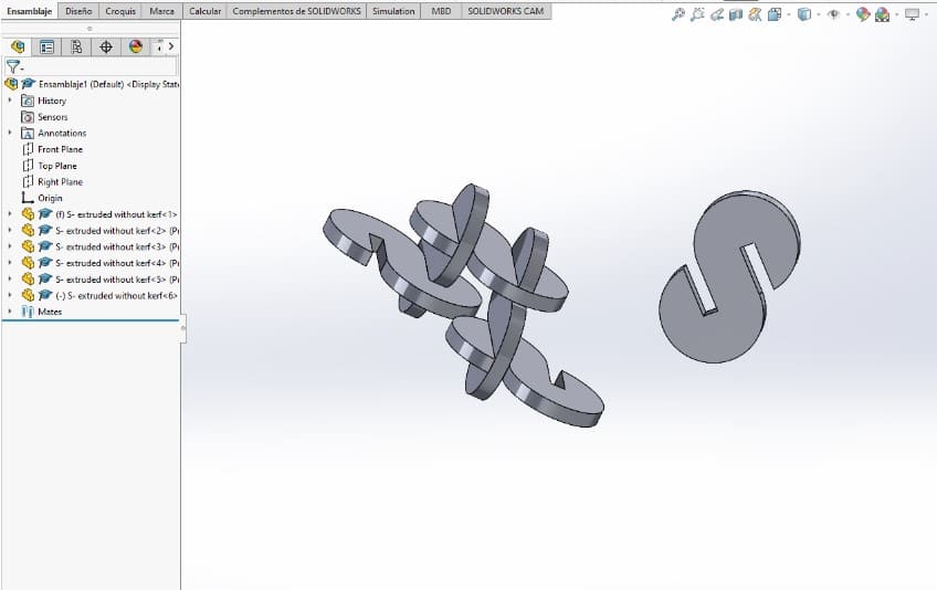
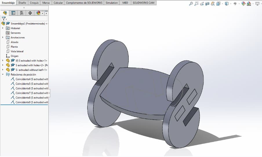
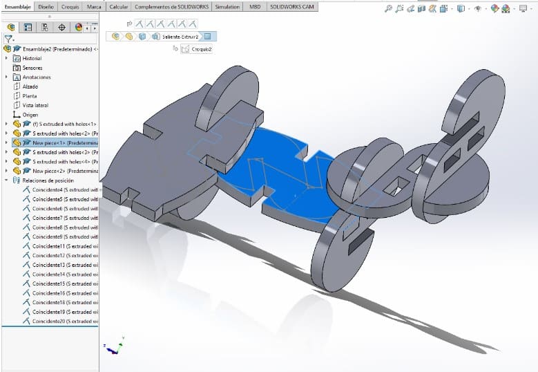
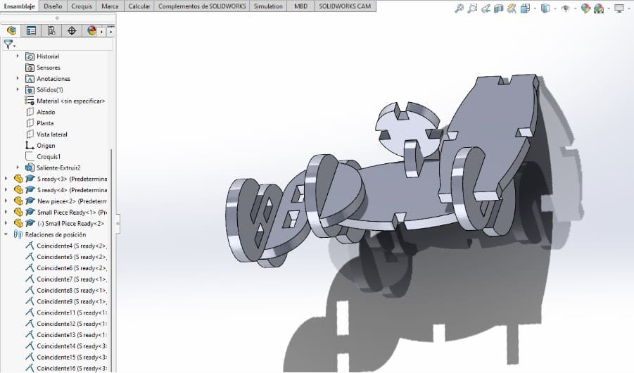
- Having defined the shape, I extruded it with the same thickness of the material I would use, as I worked with 3mm MDF that was the measurement. I saved the first piece at this point, and created a "new assembly" to check how several pieces like this one would behave.

- To build the assembly I used the tool “mate relations , then connected the faces and edges of the piece on a realistic position. Here I liked the result, but i noticed It wouldn't allow me to build much more than chain-like structures, so I decided to make adjustments to the design.
- I created a new sketch on the back of the drawing to make another type of slot for a different piece. There I made a rectangle shape from the “midpoint” of the outer vertices of the shape. I used some ”sketch relations” and reference lines to rotate the rectangle to have the same orientation as the slots .

- Then I drew a square of 3x3mm in the middle to separate the rectangle in two holes for a better connection with a new piece. Then I defined the rest of the sketch and created a new "extruded cut" operation that considered those two holes. Here, the first piece was finished.
- Next piece: "Link piece"
To draw the next part, I kept working on the same piece but a different sketch. This allowed me to follow some measurement and position references from the original drawing. The first thing I did on that sketch was a rectangle that would touch the edges of the original S. - Then I drew the "connectors" on the top and base of the rectangle, giving them the same distance the previous slot on the S had.
- For the next step, I used the "trim tool" to remove the longer lines of the original rectangle, and replaced them with a "three point arc" Once this was done, I defined the shape and extruded it with the same 3mm thickness.
- Then I made a new assembly to check if the new piece worked with the previous one.
- I didn't like the way the curve looked with the assembly, so I retroceded.There I made two more cuts at the middle of the long part, using the same depth and measures as the previous ones.
- After the changes, I checked the assembly and it worked better, but I thought I needed another piece to make the kit more versatile. To finish this piece I saved it as a copy of the first one, so I could keep the changes without affecting the original.
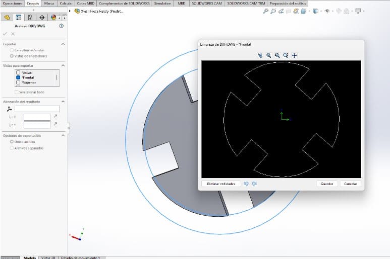
- Next piece: "Small piece"
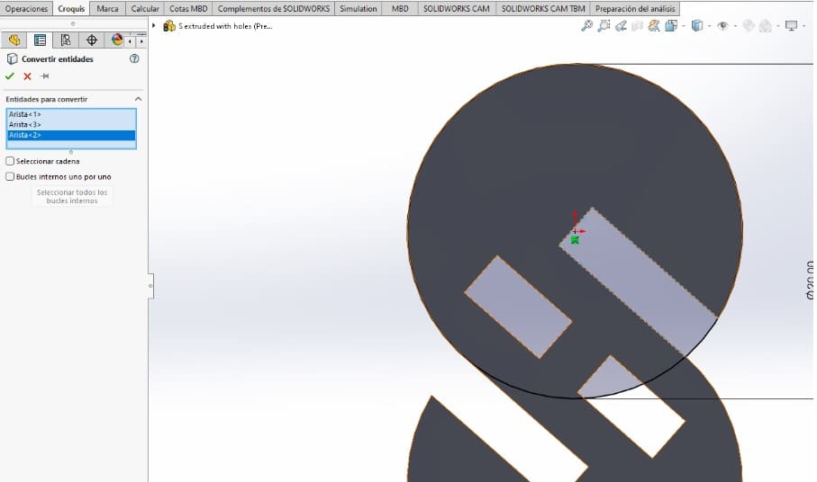
To draw the last piece, I re-opened the original S piece to work with it as a reference. I repeated the process of making a new sketch on one of the faces and sketched a circle with the same measurements as the first one. - Next, I used the "Convert entities" tool to re-use the lines from the original shape. I took the lines from the original right slot.
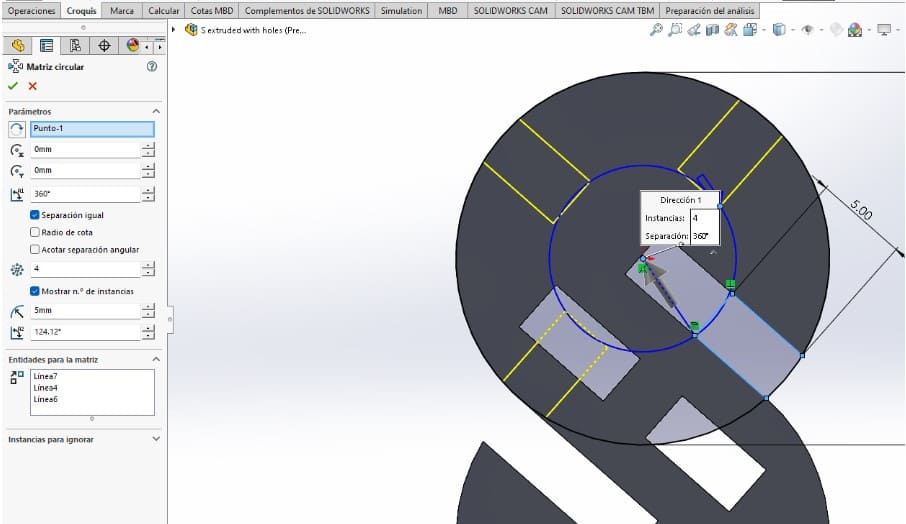
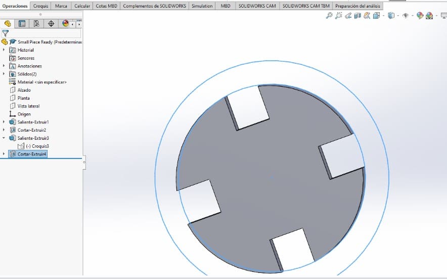
- But then, I changed the measurements and defined them to be the half of the original. Right after I used the tool "circular pattern" to create four more.
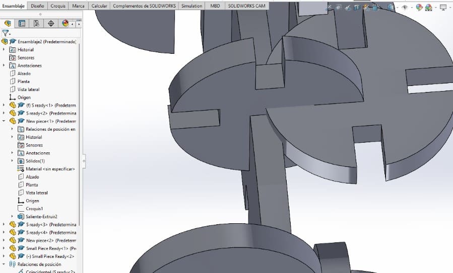
- Once I had this, I extruded the shape the same 3mm as the others and added to the assembly to check if there were no problems. When I did I noticed the size of the circle was too big to assemble with the other pieces.
- To solve that problem, I created a new sketch on the front face and drew a "donut-like" shape, that I used as a gide to make an "extruded cut" that would reduce the size of the cross.

---- How do I make my design parametric? ----
It's important to know that making your design "parametric" will make it possible to adjust the measurements and follow a relation between the original size you had. I will explain it with a document I used to check the Kerf, then how it looked like with my pieces.
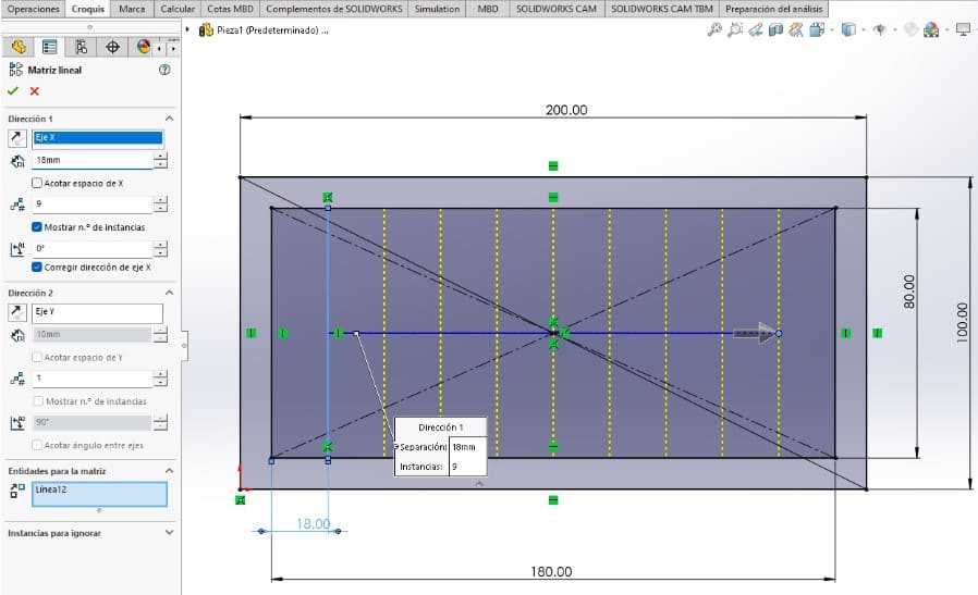
- I drew a rectangle as a frame, with ten bars inside and gave it measurements. (You may make your design parametric once it has dimensions).
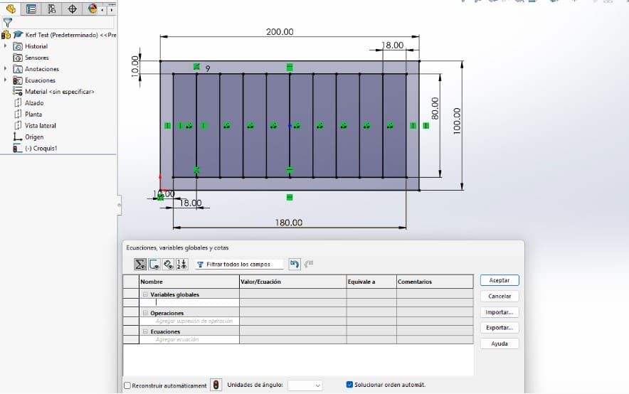
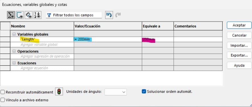
- The first step to make it parametric is to open the "equations" tool. This will appear as a table.
- Then I found the three main columns: global variables, value, and evaluates to. I filled the yellow first with the name of the variable I wanted to create, then assigned it a value on the blue column, and finally clicked on a checkmark so the pink column would fill automatically with the information from the pink one.
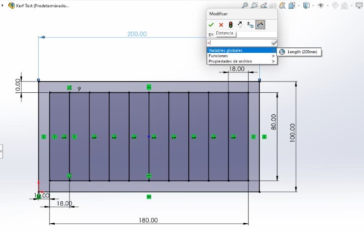
- Once I finished adding the variable, I modified the dimensions I already had by clicking on them, deleting the current measure, then clicking on the option "global variables" and then choosing the one I wanted to link to that measurement.
- Then I did the same for each of the dimensions, once it's done there appears an "equation symbol" next to the measurement.
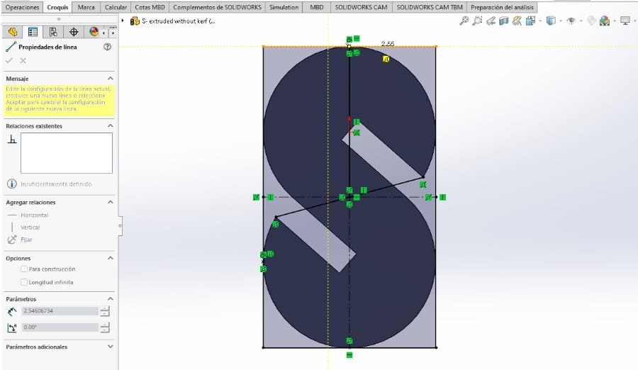
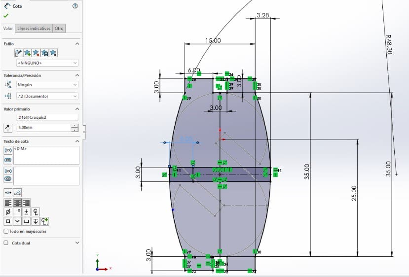
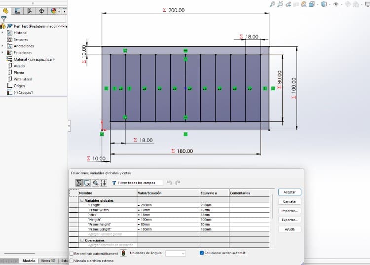
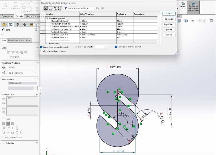
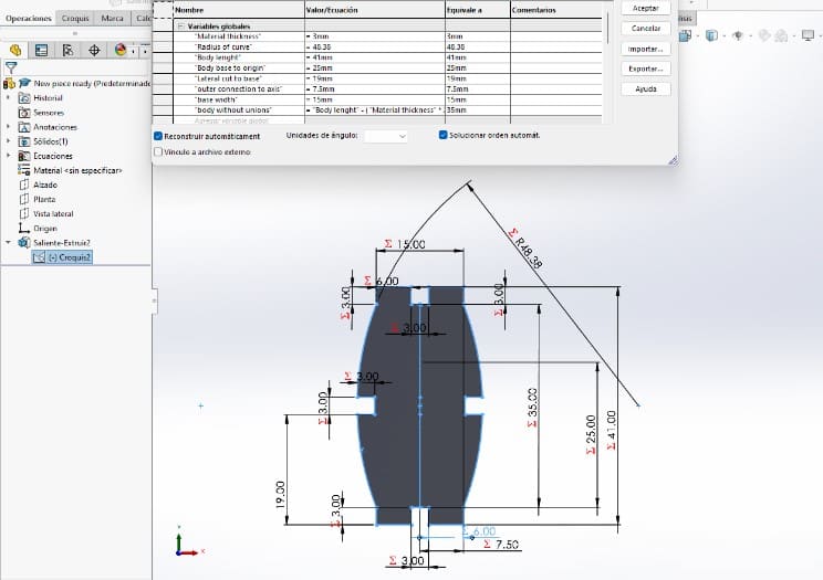
- This is the way the "S piece" Looked like once it had parameters. I also deleted some dimensions and replaced them with sketch relations.
- This is the way the "Link piece" Looked like once it had parameters.
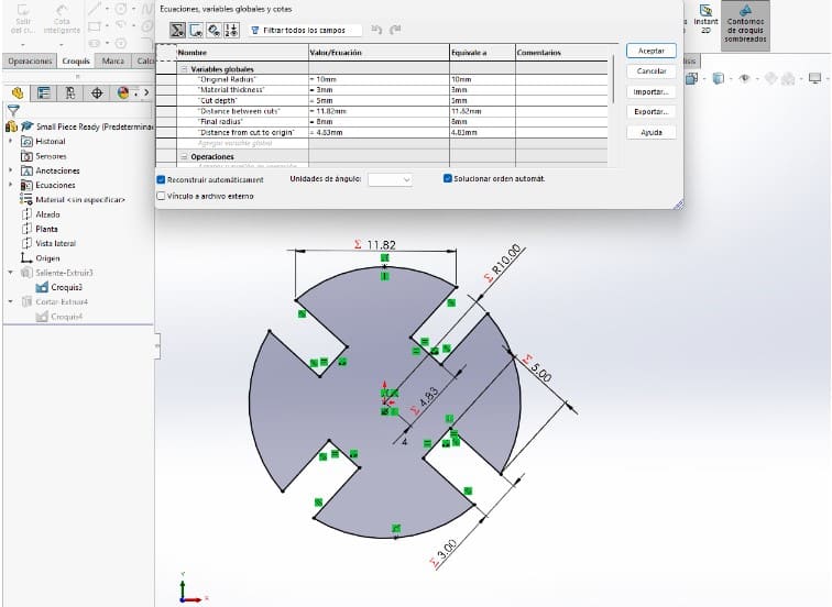
- This is the way the "Small piece" Looked like once it had parameters.
---- Making a press-fit construction kit: Exporting Phase ----
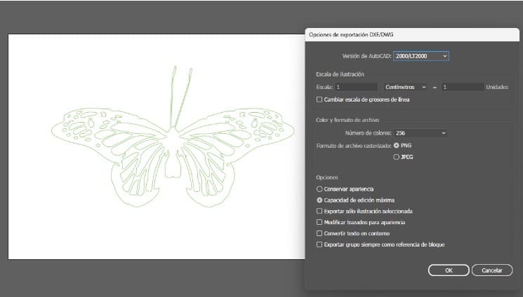
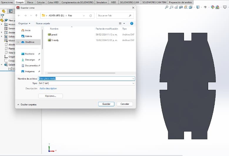
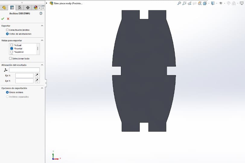
- Once the pieces were ready, I saved them using a DXF format, for the laser cut.
- Then I selected the face I wanted for the drawing, I considered the frontal face for all my pieces.
- When I clicked on the green checkmark, Solid opened a preview of the silhouette that would be saved.When you click on "Save" it goes to the folder you choose. I did the same process with my three pieces.
---- Making a press-fit construction kit: Cutting Phase ----
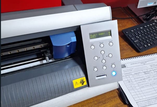
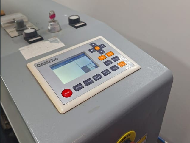
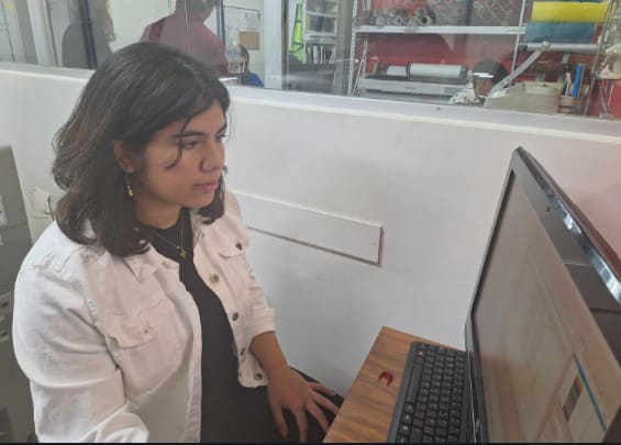
- The first step was to turn on the machine. It had 3 different interruptors: one for the main power, one for the fan and the key. This key also has another one that works with an USB to connect the machine to the program in the computer.
- Then it was time to place the material on the working table, and adjust the laser position (still without turning it on). To modify the laser's position, there are controllers on the machine to move it up and down and on different axes. To be able to move this controllers I pressed the "Z/move" tool. Leaving an aproximate distance of 5mm between the laser and the material.
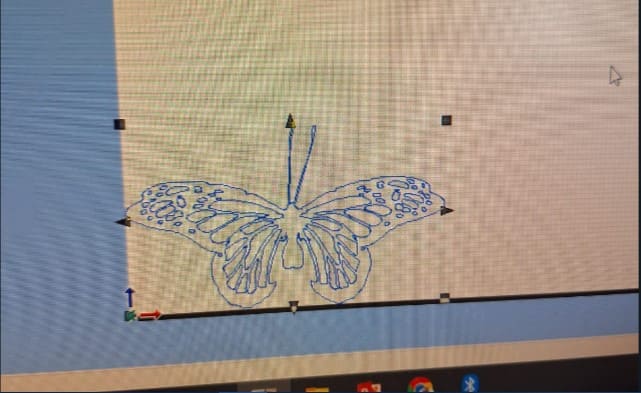
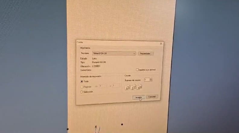
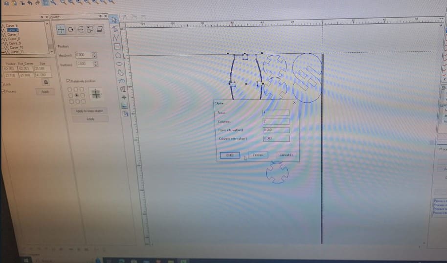
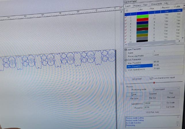
- Once those elements were set, I had to look for the archive I wanted to use and open it into the program. The program it's called "Smart Carve" . To open a file in it, it's necessary to use the "Import file option"
- Then, as I had different parts, I opened all of the files in the same working space of the program. I "cloned" them by clickinc on the right click and then the tool "clone". Also the copy-paste tool worked to set many pieces at once.
- Then I used the "go scale" option to make the laser move through the material and determine if the design would fit there. It did!
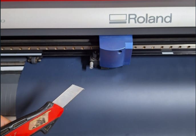
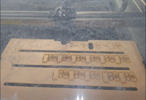
- Next, I turned on the laser and put it to the max. It was time to cut. But here I had my first mistake, because I didn't check if the parameters of the laser power and speed were correct for my material.
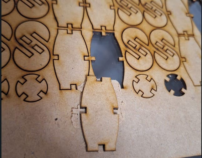
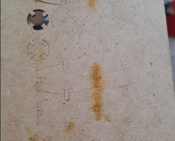
- As i didn't check propertly, I only engraved the material, It barely allowed me to pop out some pieces by pressing them, but that wasn't clean, so I had to repeat it.
- For the next test I only modified the laser power slightly, but the speed remained the same, so it didn't cut again (This is the back).
- I kept testing with different parameters until finally it worked! I felt too happy, because at my first try (the one I made to check the kerf only) I got clean cuts but I didn't remember the parameters, so this time I needed it to work and after 4 attempts it did! Here I leave the parameters I used for 3mm MDF.
- The last step to check my pieces was to check how stable they were, I assembled different structures and it worked preety good.
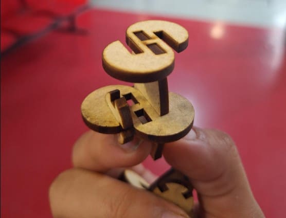
Final Result!
Description for Image 1