WEEK 15
WILDCARD WEEK
What is Lithophane?
It is a technique that consists of creating relief images on a translucent surface, so that the image can be seen clearly once the light passes through it. This is possible thanks to the variations of material in each layer, forming lights and shadows.
When I was told that I could play with the textures of a print, I did not hesitate and wanted to try how it would look, at first because I came to think that with this technique I could make the body of the lamp of my final project, but it would be a lot of material and time involved, so I opted for just making the top part of the lamp.
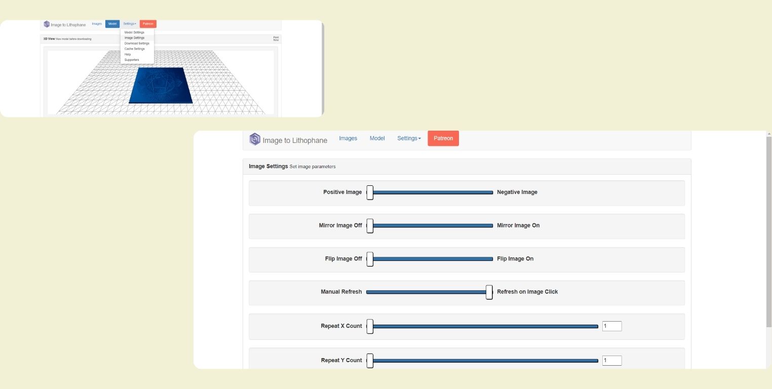
- For this assignment, I was helped by an internet page that converts the image into a ready-to-print lithophane. This is the overview of the “Image to Lithophane” page.
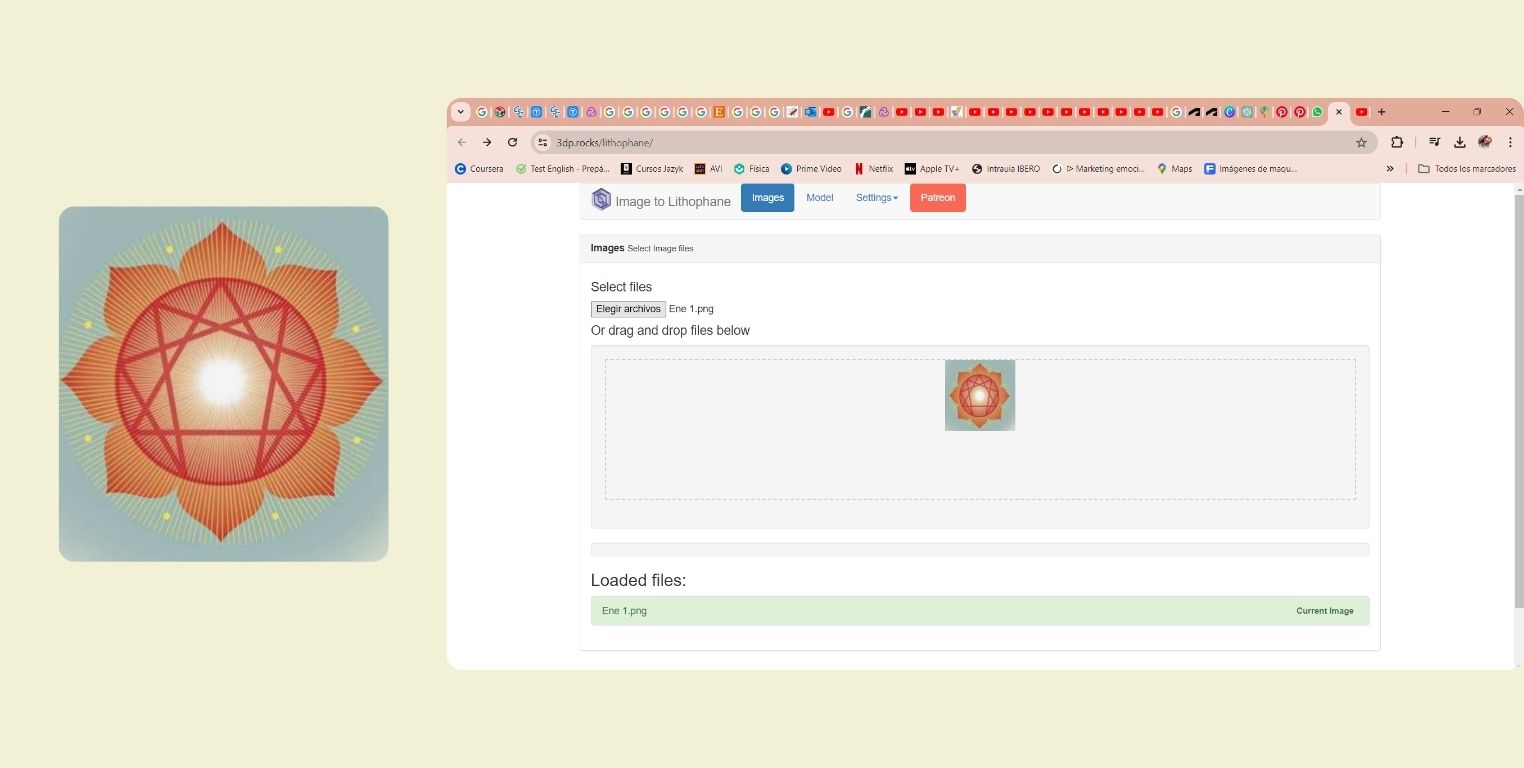
- This is the image I chose for the lithophane, this one I got from the internet, but then I thought it might have been even more interesting if I had made my own with AI, maybe in the future I can do another test with that method. To upload it, in the “Images” section select the file and it is ready.
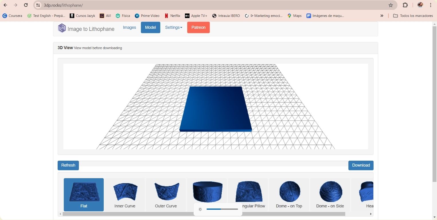
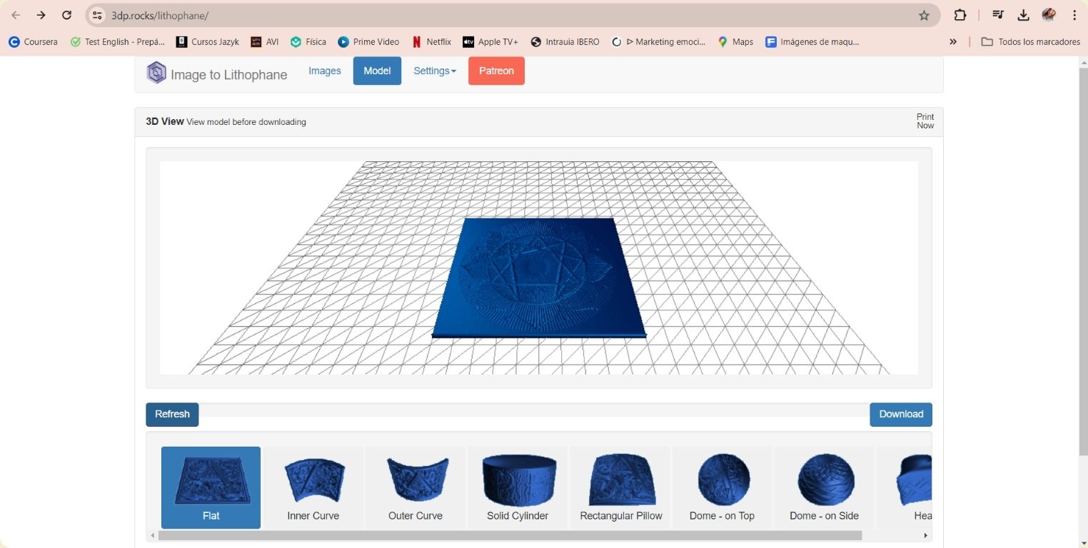
- When the image is uploaded, this is an overview with the design of the image. You can give it different shapes, some more interesting than others. The recommendation of one of my instructors was not to make it flat, but curved, because that way it comes out with better detail, but in this case, for what I want, I needed it flat. To apply each one of the models, it is necessary to “refresh” after selecting it.
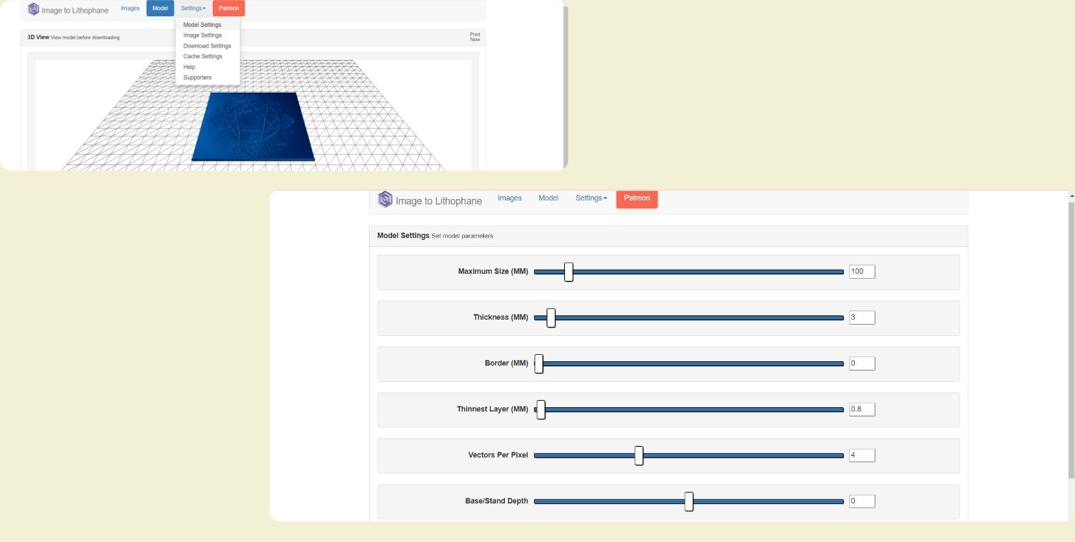
- In the “model settings” menu you can modify the size of the piece, or the thickness of the print, among other things. It is worth exploring every single thing in the menu, it is very fast.
- From the “image settings” menu I just went from a negative to a positive image.
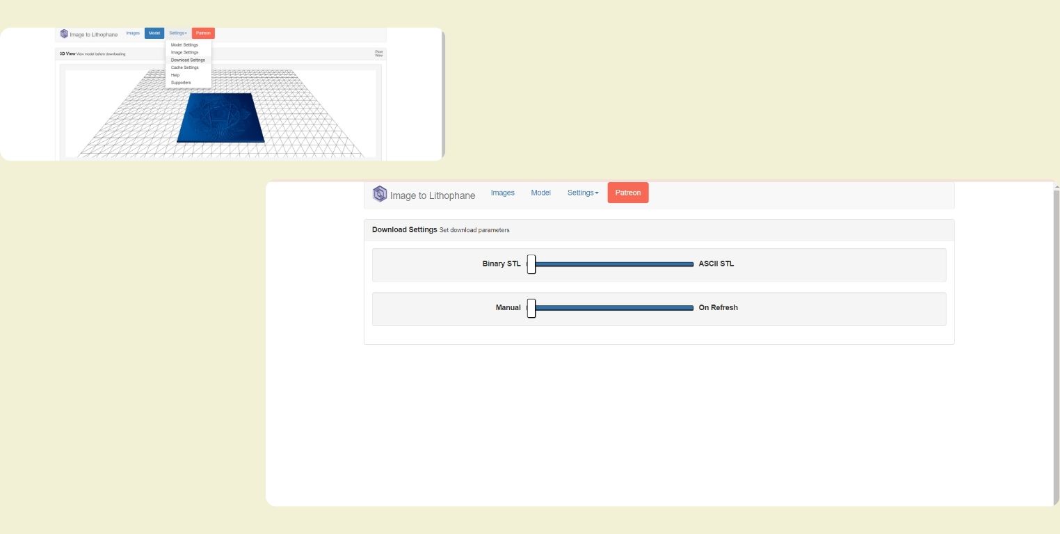
- In the “download settings” menu you can modify aspects of the download, in my case I left the default. Once ready just go back to the “Model” view and click on “download”.
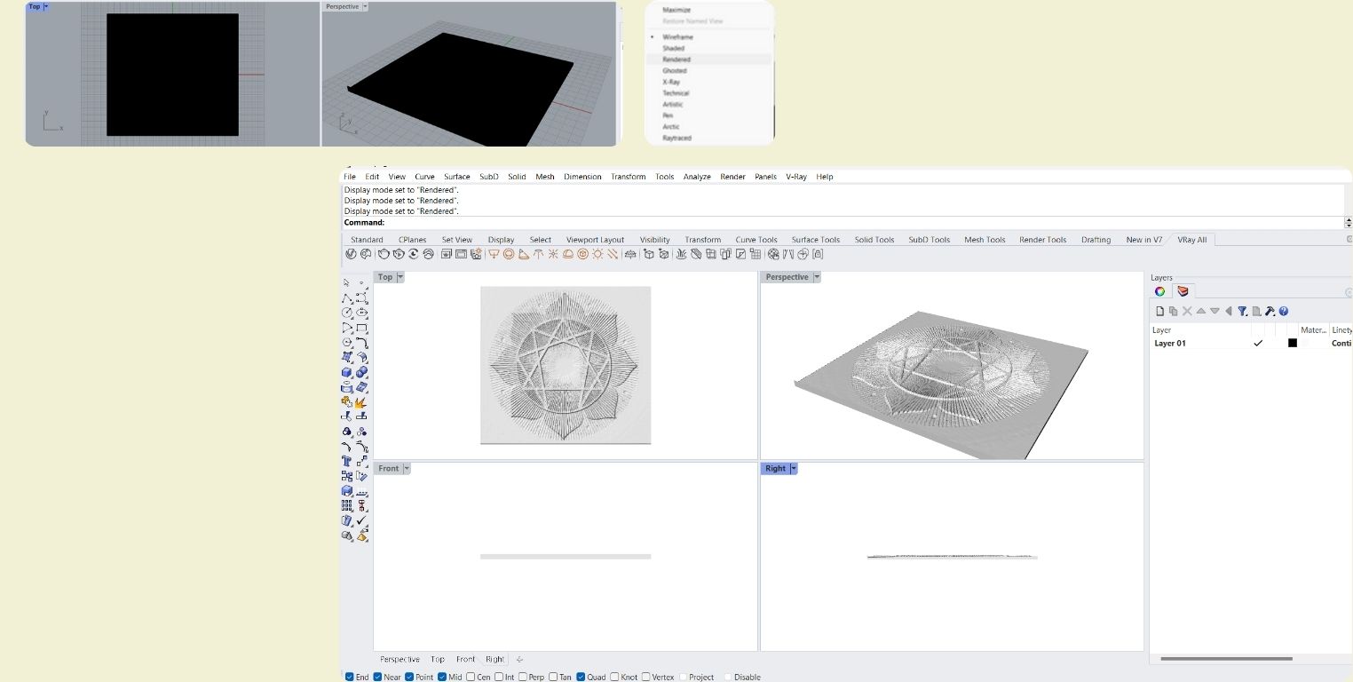
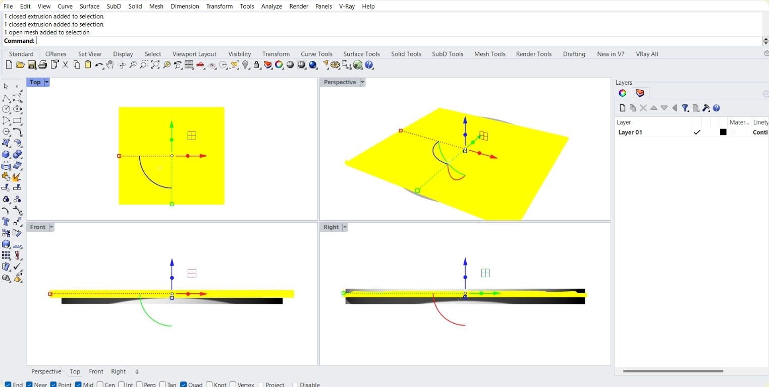
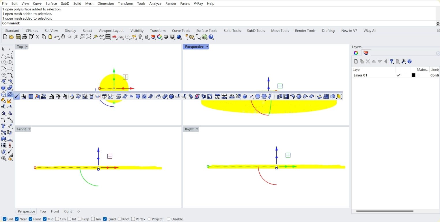
- Open in rhino and change view type to rendered.
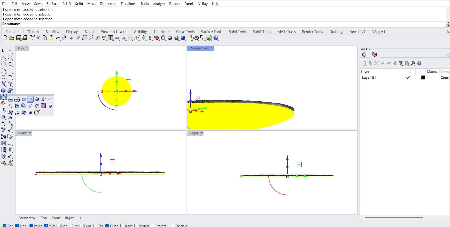
- Cylinder protruding from both sides.
- It is not a poly surface or solid, but a mesh.
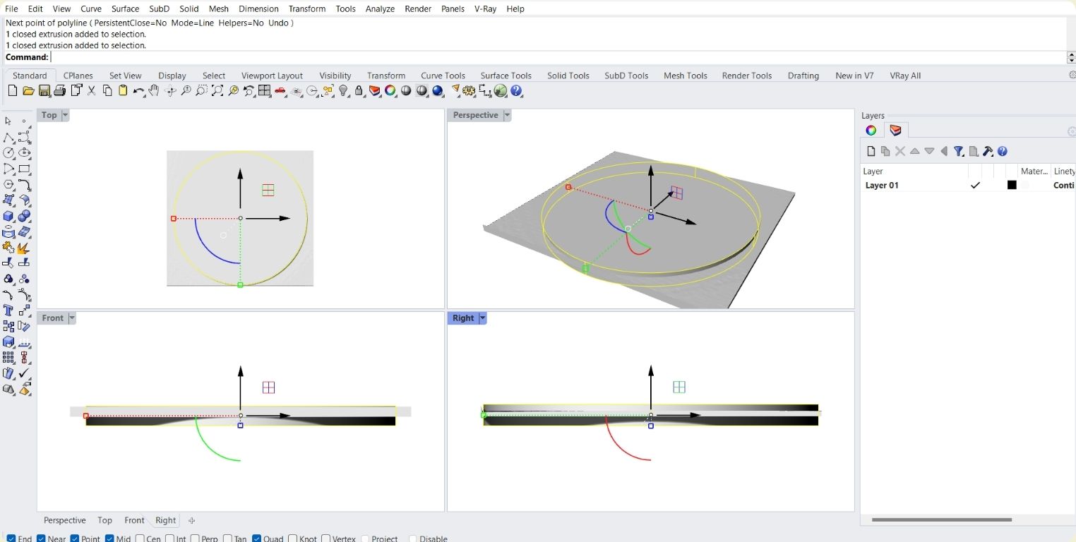
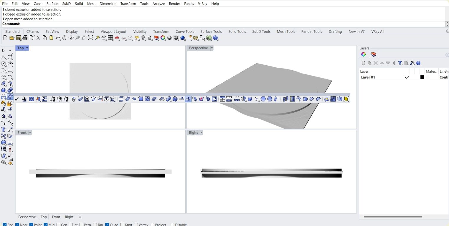
- I used the Trim tool within the mesh tools.
- I got the circular shape I wanted. I had a circular base, but not the wall, and they were grouped.
- With a cutting plane I separated them visually to explode the mesh, and then join the bottom and the top separately.
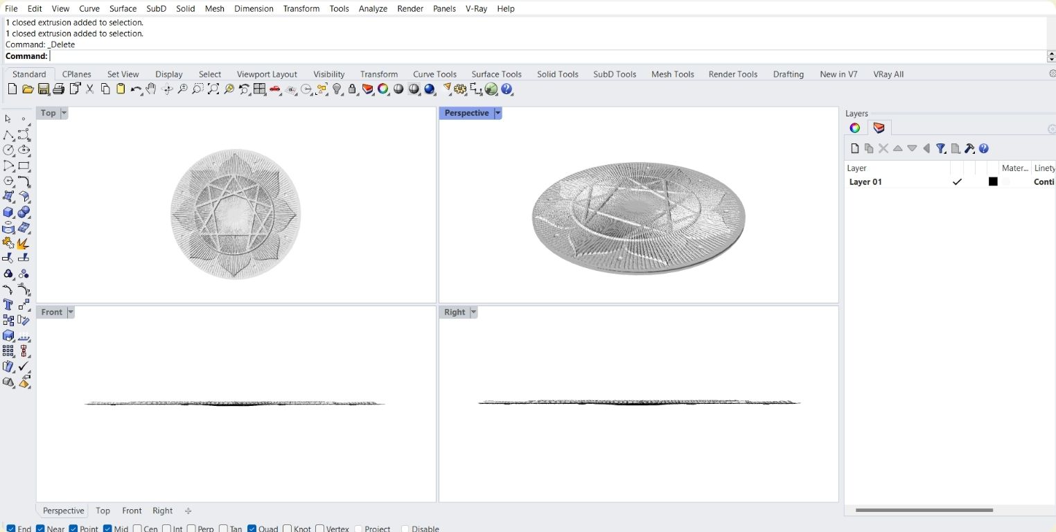
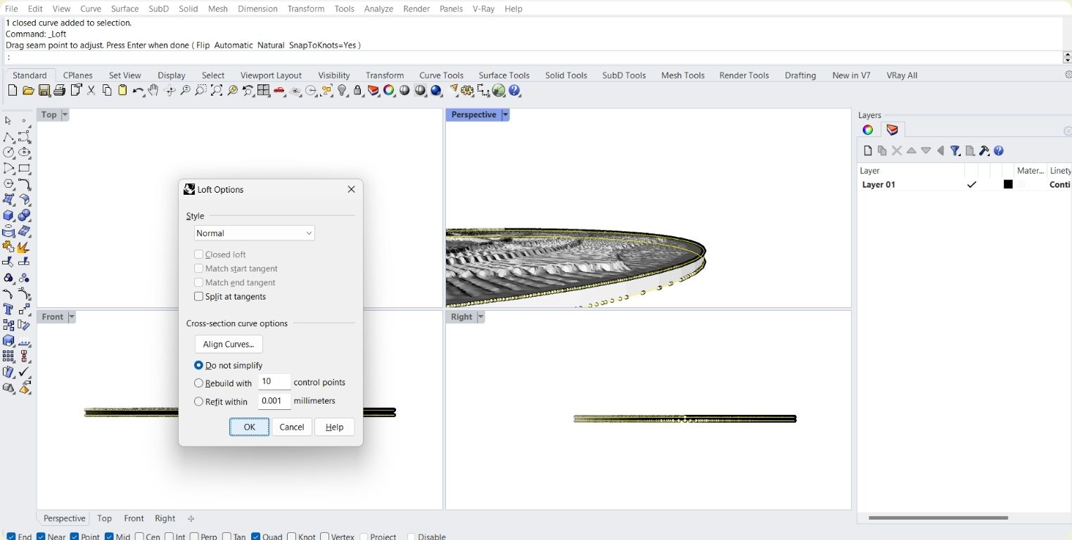
- I duplicated the edge of the two pieces.
- I selected both edges and applied a loft to them.
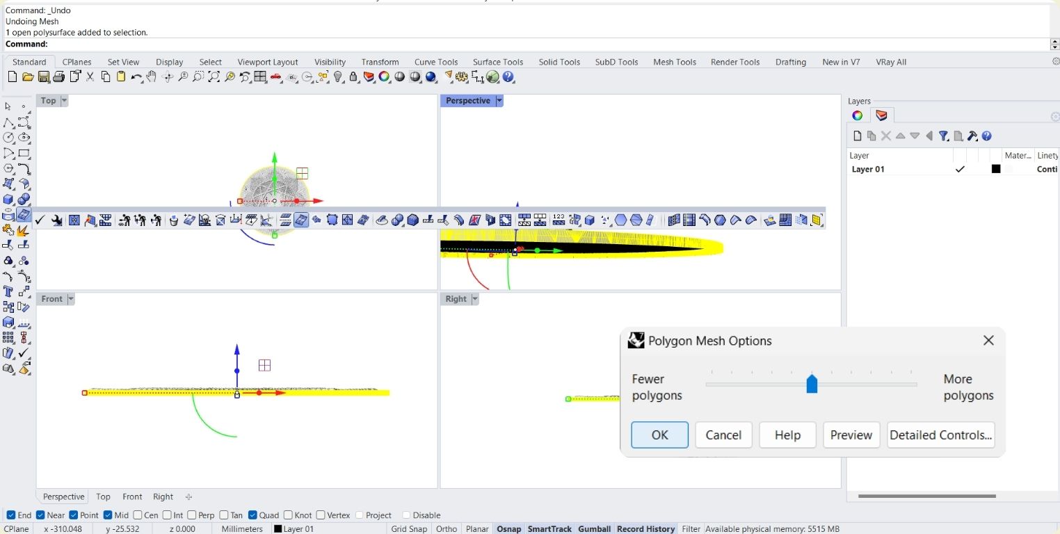
- I converted the polysurface into a mesh.
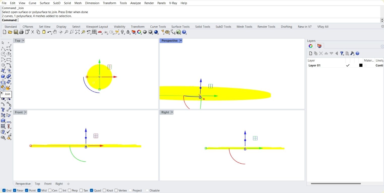
- I selected all and selected join.
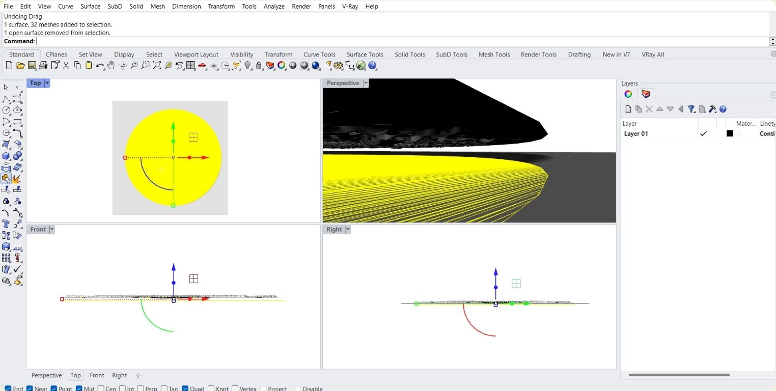
- Now when I selected it, it appeared that it was an open mesh, so I checked with a mesh tool to verify, after that it became a closed polysurface and ready to be passed to Cura.
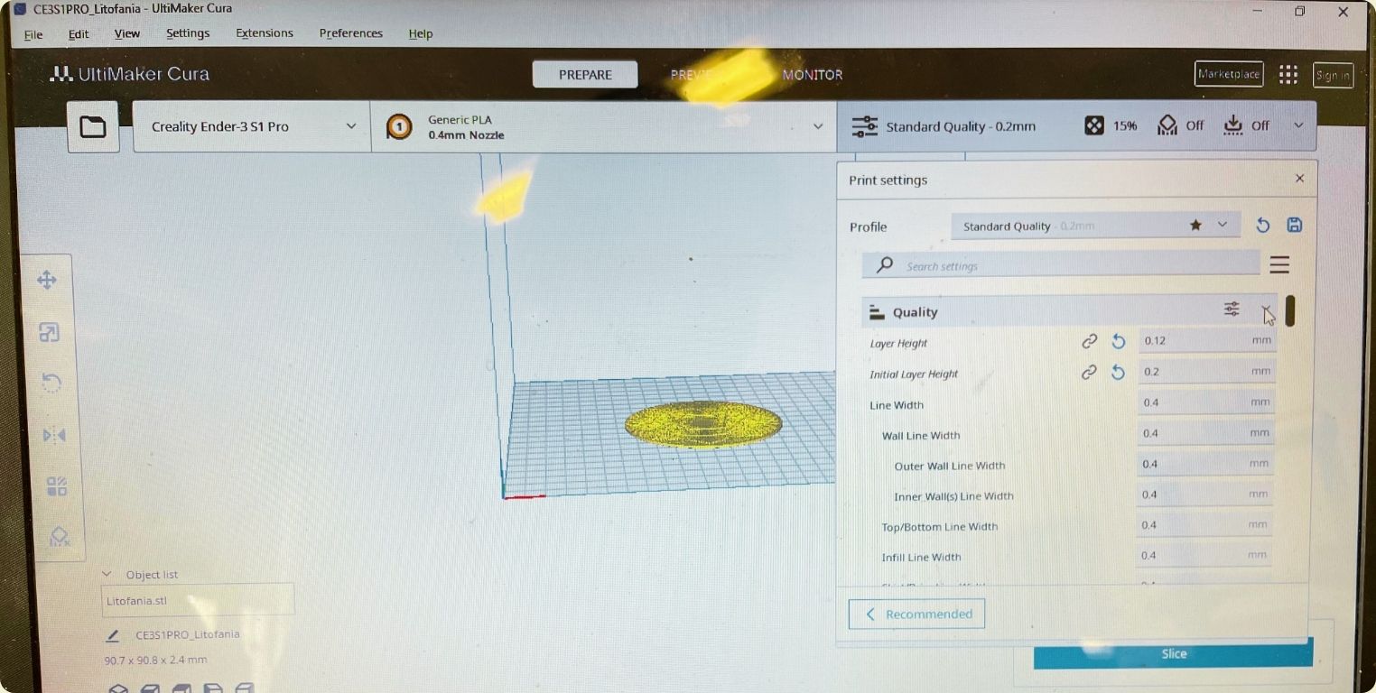
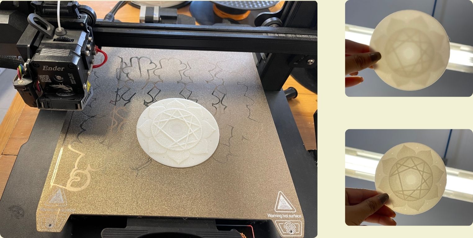
- Already in Cura, I modified the height of the layers to 0.12, and 0.2.
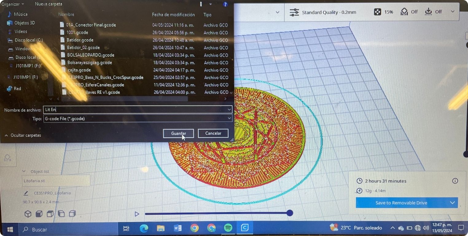
- I gave a skirt adhesion method and saved the gcode. Where it says the time, also appears the grams and meters of material that will occupy the impression.
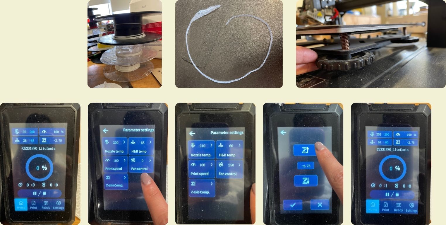
- For the impression it is necessary that it is made in white material, so that the shades can be appreciated better when it is put on a light source. Sadly we didn't have much in the FabLab in Puebla, but the remaining ones saved me. Here I realized something that was happening, and that is that when the printing started, on a specific side of the bed, the layer of material did not look uniform, so I had to calibrate the bed in the 5 points of the bed. After that, I only managed to get the same effect on the whole bed. Then I lowered it a little in the Z axis, I also increased the temperature of the material and lowered the bed temperature, and finally, I modified the fan control as well.
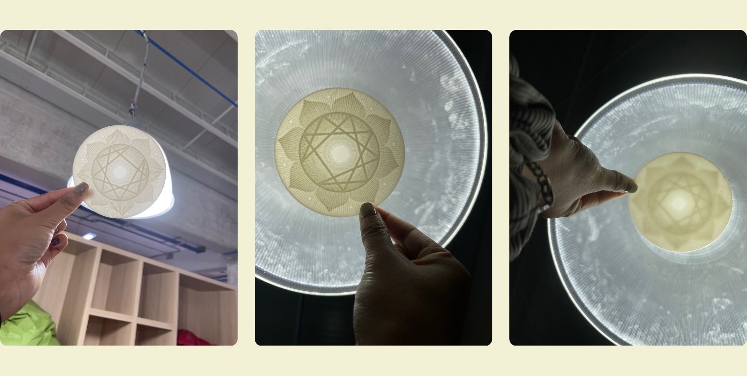
- I prayed that it would turn out well, and it did. The print came out pretty good, and I still had material left over. I did a quick test on the lamp in the living room, and it looked pretty good.
- Later at the university I found this lamp, and I wanted to test it again. I really liked the detail that can be seen. Here you can see more that from one side you can see the details better than from the other.
Conclusion
I found this technique to be quite interesting and easy to work with. However, I think the magic happens when it comes to an image with excess detail. In this case I opted for a photo of the representative shape of the enneagram, which does not have so much complexity, so even without light I think it can still be appreciated... Or even playing with the different surfaces to make lithophany can be quite interesting. For now I am satisfied to have something that could contribute to my final project.
Thermoforming
I would like to integrate here the thermoforming work I did for the final project, because there I learned to use another machine in FabLab Puebla. I did this practice in order to obtain the base on which the neopixel strip will be placed. With this in mind, let's start with the tutorial.
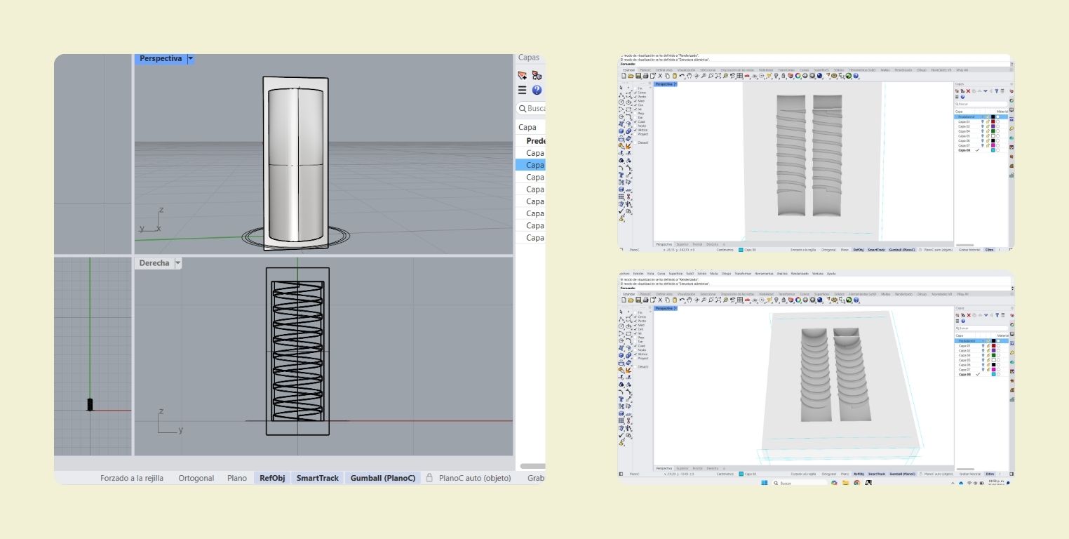
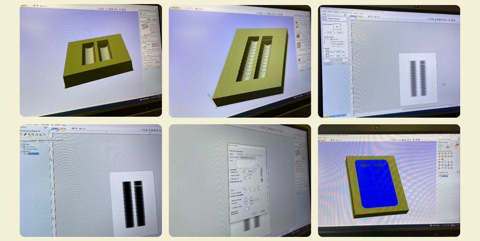
In Rhinoceros I modeled a cylinder, which inside I made some slits in the shape of an ellice, then I split the cylinder in two and joined it to a rectangular base of about 20 by 25 cm with a depth of 3 cm.
Then I ran it through VCarve to configure the cut and finish of the piece, the idea is that the 5mm indentations were the best possible portrayed, basically I was looking for a finish like the wax I used for the molding and casting week, but now with MDF. In this process I was helped by one of the local instructors to make the Router only cut to the center, where the piece was, and that the tool was not at risk in the peripheries.
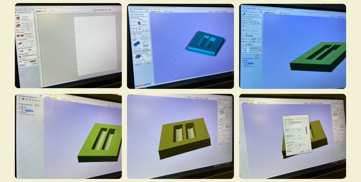
To do this, a day before I glued two 1.5 cm thick MDF pieces of wood to obtain my cutting piece and then place it on the cam table. In the same way I got the pieces and their respective adapters to the Router nozzle.
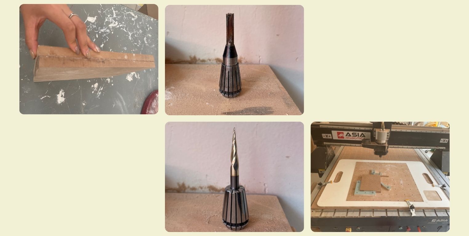
With the help of the monitor I guided the cutting and finishing. Between these processes I also had to change the tools I would use for each one, allowing me to learn a little more about this process, as I had not had the opportunity to change the nozzle adapter before.
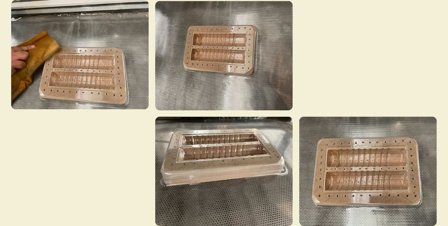
Once the cut was ready in the Router, the next step was to make some small holes around it with the router, for this I had to get another piece of wood that I could put underneath and hold both with the help of some presses so that they would not move. This is necessary because with this piece I had planned to do a thermoforming that would give me the final piece of the internal base, and when doing thermoforming, especially for details it is necessary to have perforations in which the air can be sucked better.
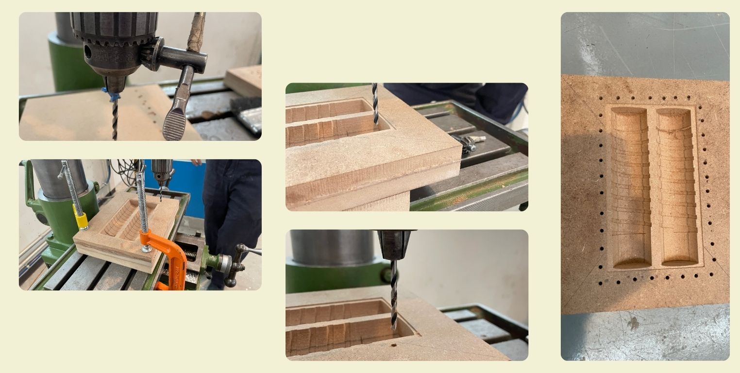
Once the larger perforations were ready, I moved to a work table where I clamped my pieces again, and with the help of a mototool and a thinner drill bit I made the perforations in the middle of the indentations. In the last photo in the lower right corner you can see that I also sanded the corners a bit to ensure that there were exit angles and the part would come out of the thermoforming.
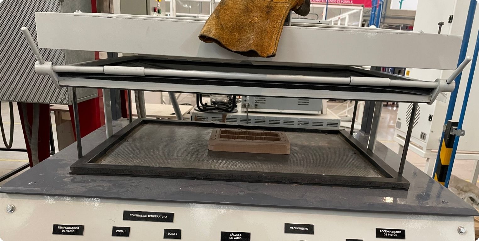
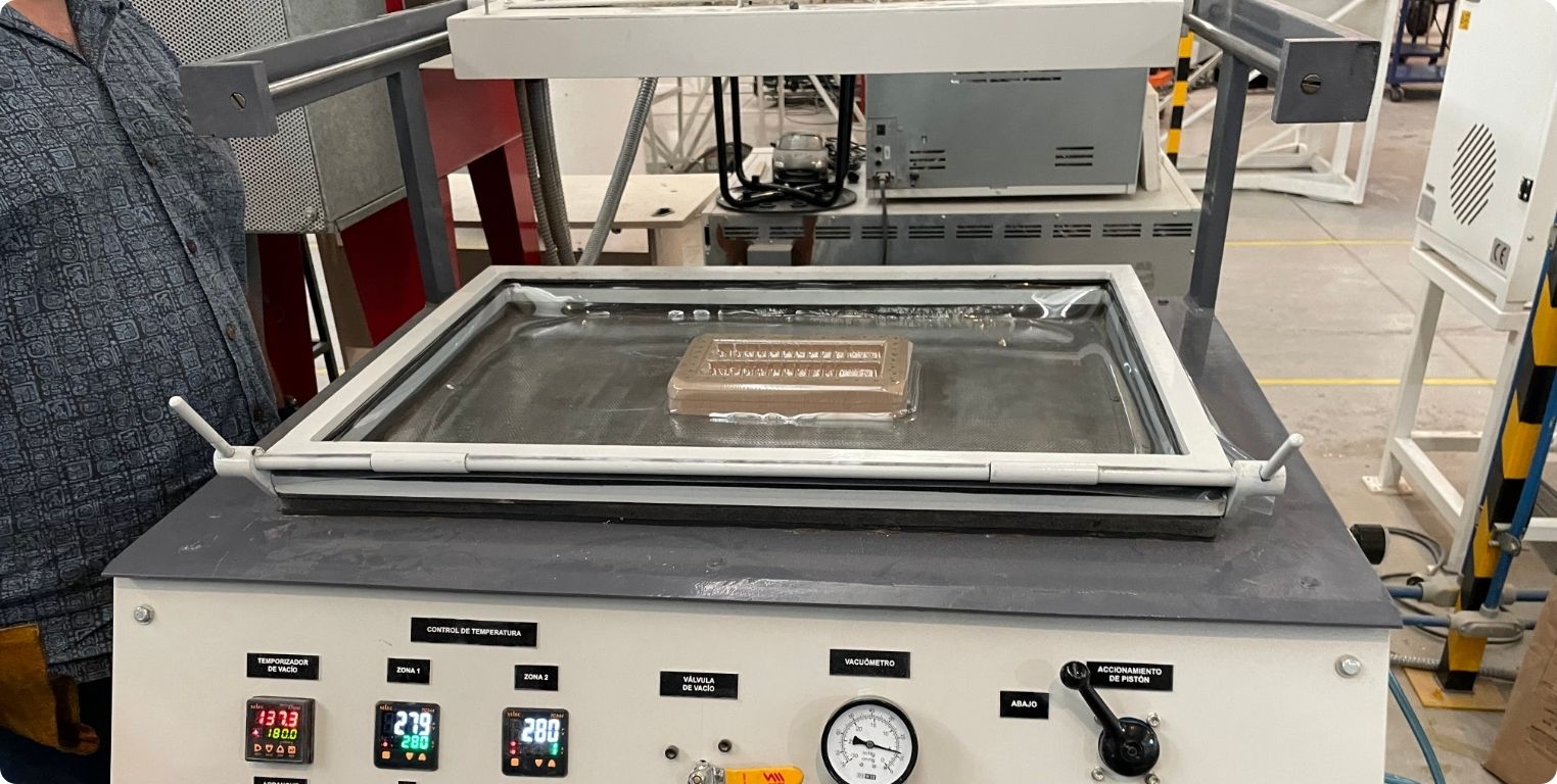
In the thermoformer the first thing to do is to place the material on the base and secure it, in my case I used PET, because it resists heat quite well and the neopixel strip could be heated a little, so it would hold quite well.
I was also helped by a guide made by the local instructors at all times, although I must say that they also accompanied me in this part of the process.
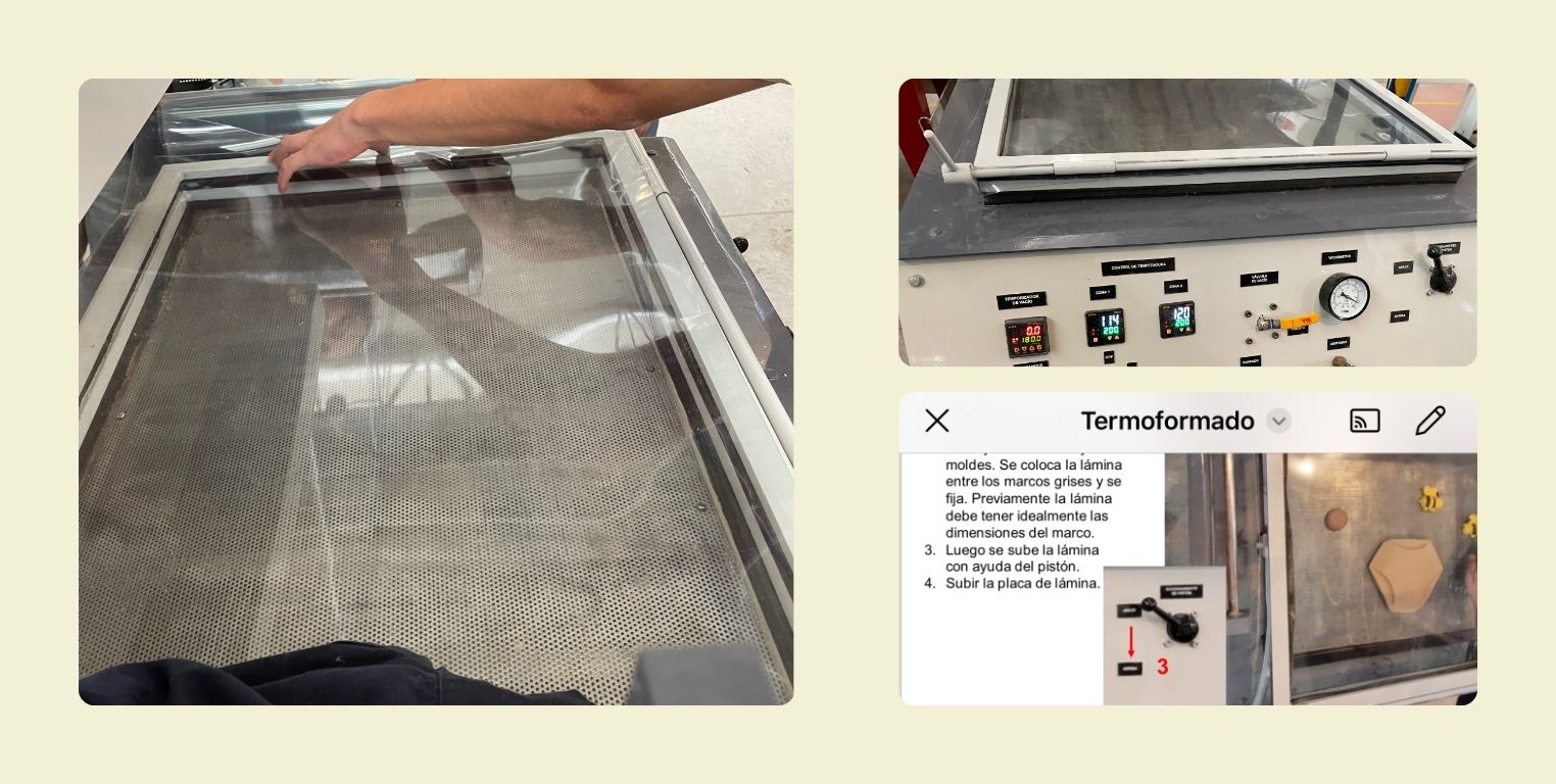
It is important to set the temperature on the two screens of the thermoformer so that it heats evenly, at the beginning it is set and a countdown starts in which the machine gets ready.
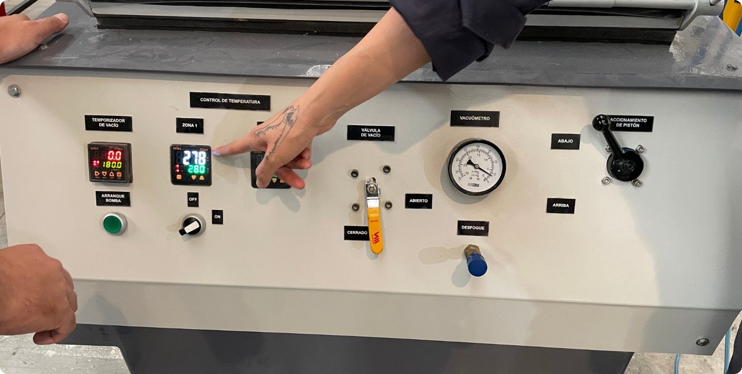
At this time the top white part should be at the bottom, and for the moment it is not necessary to raise the material.
After a while it can be raised to begin to place the piece to be portrayed with the machine in a position that helps, it is usually recommended that the piece leaves a considerable margin at the ends.
When it has reached the countdown, the white base is moved so that it is on top of the material and begins to heat it. This must be done carefully, as this is the part where the heating elements are already hot, so it is best to wear gloves.
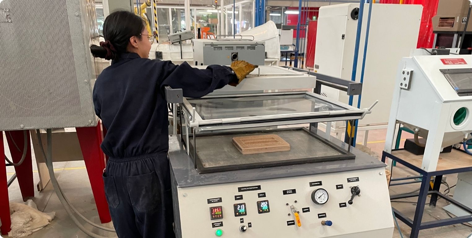
I left a glove there for when I have to remove the base again.
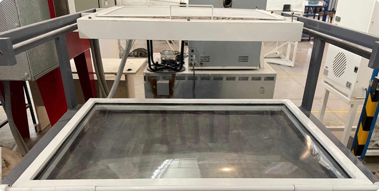
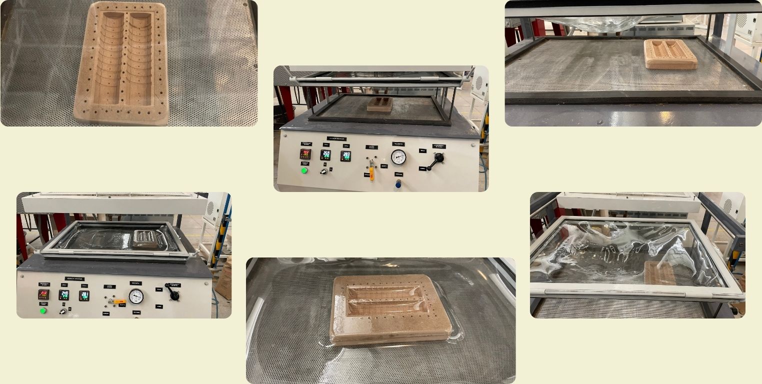
You have to wait until the material starts to hang considerably as in the photo.
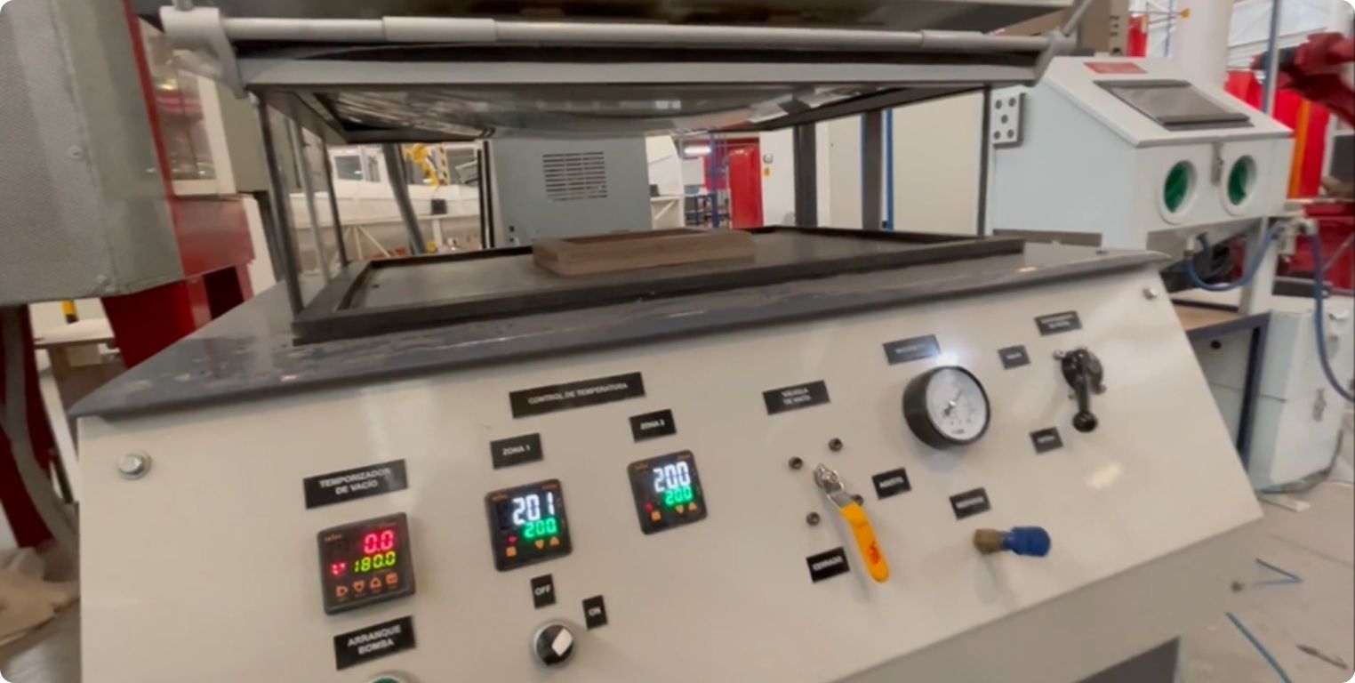
Once it is ready, the material is lowered by raising the black lever.
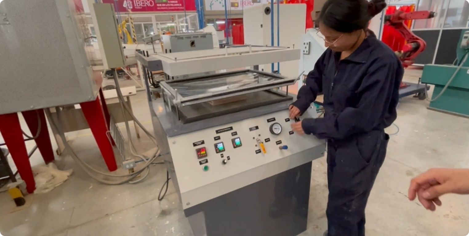
And to start the vacuum it is necessary to raise the yellow lever.
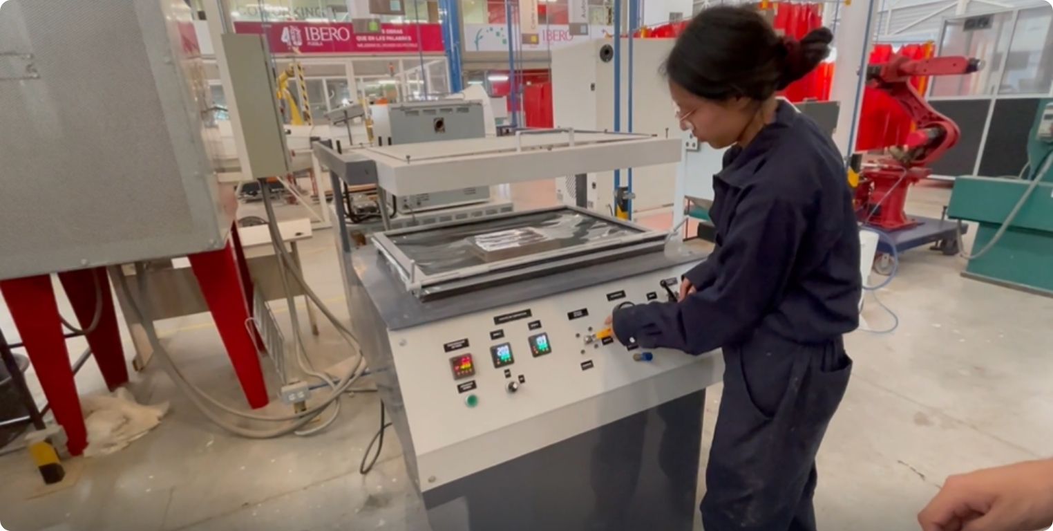
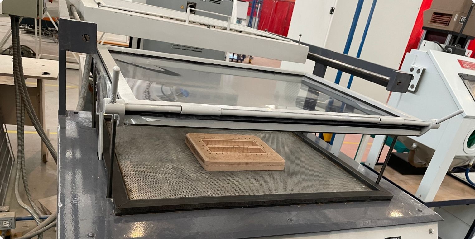
Something like this is seen after all the vacuum is gone. It is necessary to wait until it cools down, and for that the top white base is removed again.
This is what a part looks like after thermoforming. With the help of a glove you can check if it is cool enough to remove it from the base.
And although I explained it in a simple way and it seems that it came out the first, the truth is that not, here some photos of the trials and errors that had to happen before it came out successfully.
I also share with you a little video of me in this process.
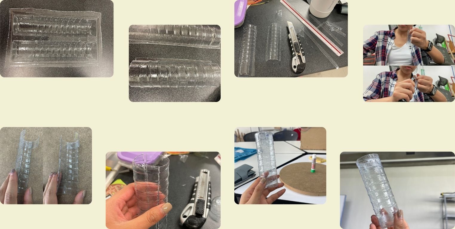
The last thing to get the base (finally), was to remove the MDF piece, and start to cut little by little the two halves of the cylinder, and then join them into a small but nice PET cylinder. That's how it was ready for the neopixel strip.
Final Proyect