WEEK 13
ENBEDDED NETWORKING & COMMUNICATION
During this week we learned how to communicate microcontrollers with each other, and there can be different ways, in the local class we had they explained 3 ways to do it so we could decide which one to use for this week, below, I attach a brief description of each one, and I also invite you to click here so you can see this week's group assignment.
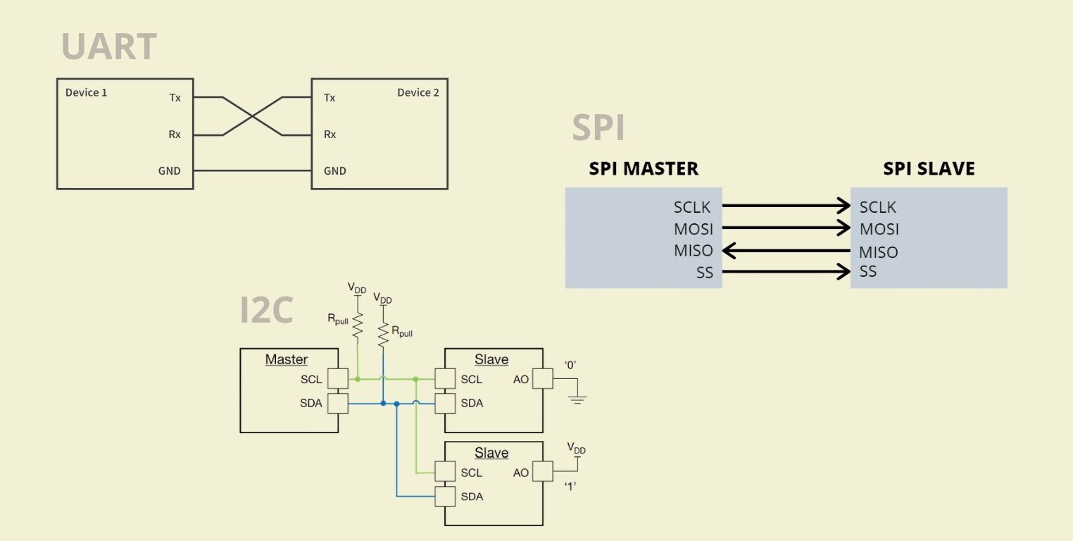
UART (Universal Asynchronous Receiver/Transmitter)
Data is transmitted and received bit by bit through a transmit line (Tx) and a receive line (Rx), for this it is important that the devices are configured with the same baud rate (bits per second).
Advantages:Simple and widely supported. Only requires two wires for communication.
Disadvantages:Can be less efficient for long distances and higher data rates.
SPI (Serial Peripheral Interface)
Uses a clock line (SCK) that synchronizes data transfer, a master to slave (MOSI) data line, and a slave to master (MISO) data line, plus a slave select (SS) line to select the device to communicate with. Data is transferred simultaneously (full-duplex), allowing bidirectional communication in real time.
Advantages:Very fast and efficient for transferring large amounts of data.
Disadvantages:Requires more cables (4 or more) and management of multiple slaves can be complex.
I2C (Inter-Integrated Circuit)
Uses two lines, SDA (data) and SCL (clock), to communicate multiple devices on a shared bus. The master controls the clock line and starts communication by sending a start condition. Data is transferred in 8-bit packets, followed by an acknowledgement bit (ACK) from the receiver. Supports multiple masters, although most implementations use a single master for simplicity.
Advantages:Allows communication with multiple devices using only two wires.
Disadvantages:Slower speed compared to SPI and can be more complicated in terms of addressing and protocol.
As I didn't want to suffer too much this week I thought I could do something simple with 2 XIAO's, an RP2040 and an ESP32C3 so that, when pressing the button of one, it would turn on the led of the other. And for this I first verified that the leds and buttons of both worked by running a code to turn on the corresponding led.
The code is very simple, the pins for the buttons and the led are defined, in the case of my boards does not change, only in the RP2040 I added the other two leds that the board has, then I configured the leds as outputs and the button as input, and finally I added a condition that when the button was pressed, it would send a signal to turn on the led.
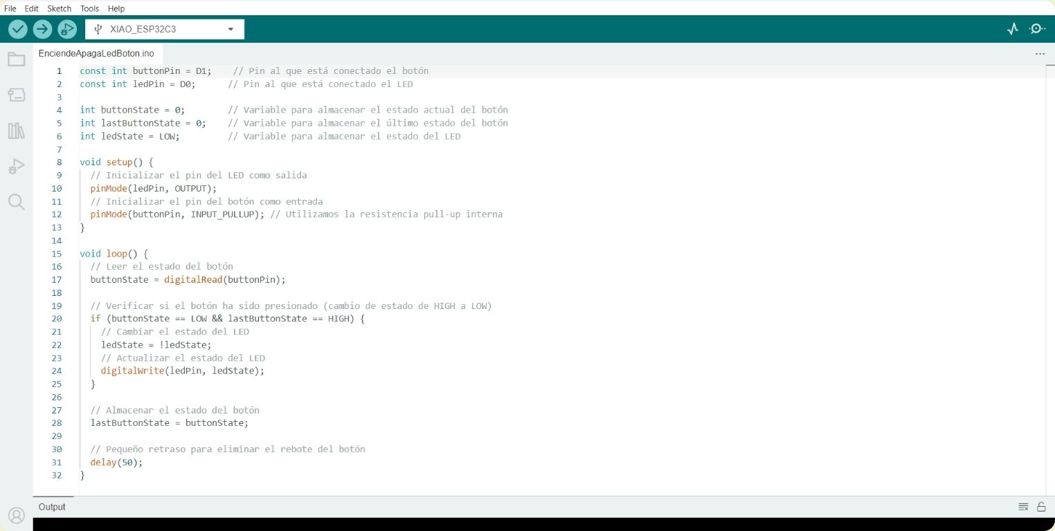
I know I should have chosen another color of led, because the green is almost imperceptible, but here is the quick video of how it looked.
I used this same code to verify that the 3 leds on the RP2040 board would turn on, I just modified it to add the new leds, while everything else remained the same.
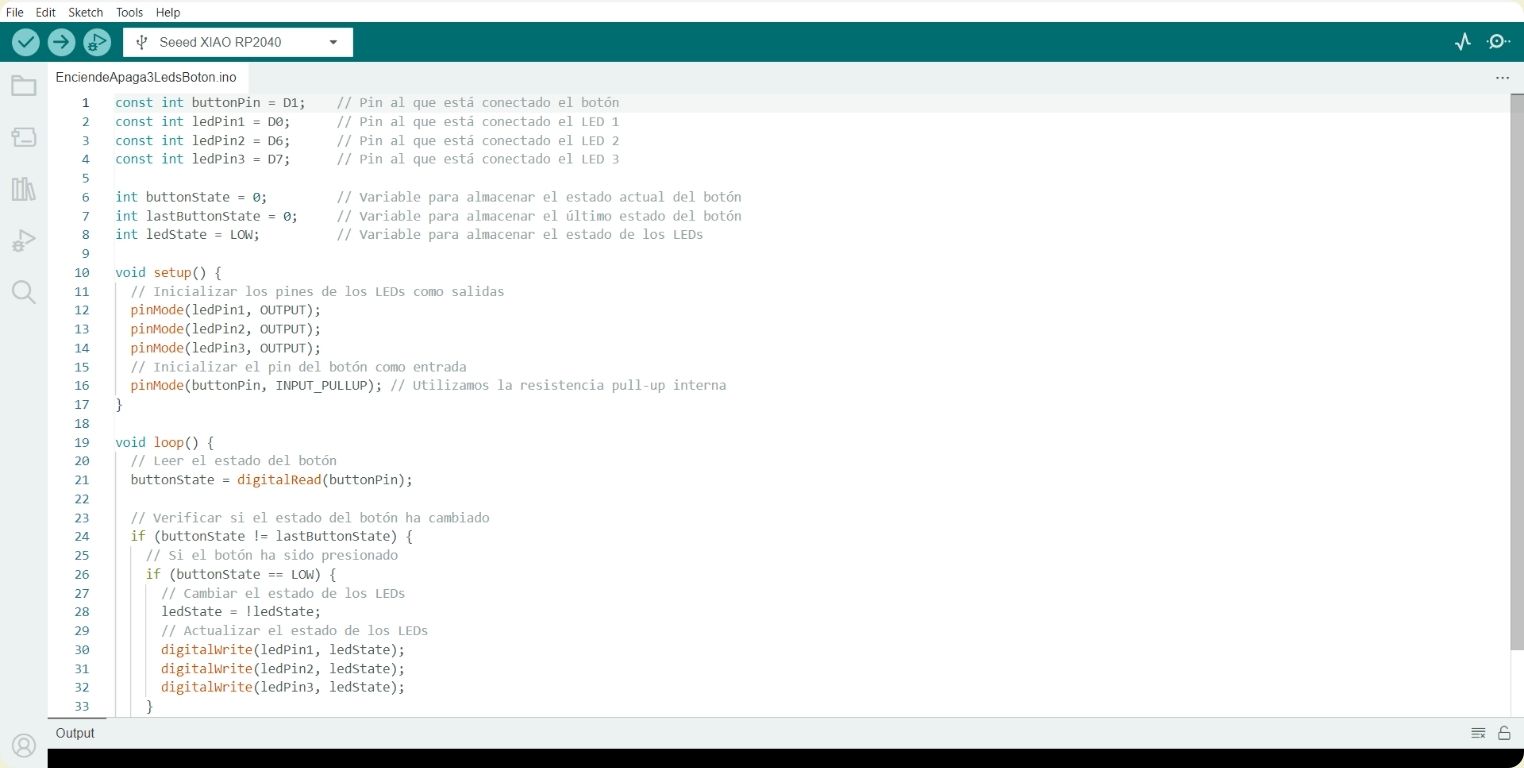
And here the video of how they turned on the RP2040, whose leds are a different color than green as in the previous board and are seen without problems.
I2C CONNECTION
I chose this type of connection because it is fairly simple to understand, but also because my other choice might have been a UART, but I didn't have the pins for it, so I went back in time a bit to understand how it worked. Basically there is a master and a slave (or several), which receives an indication from the master, in this case I wanted that, when pressing the master's button, the slave's leds would turn on.
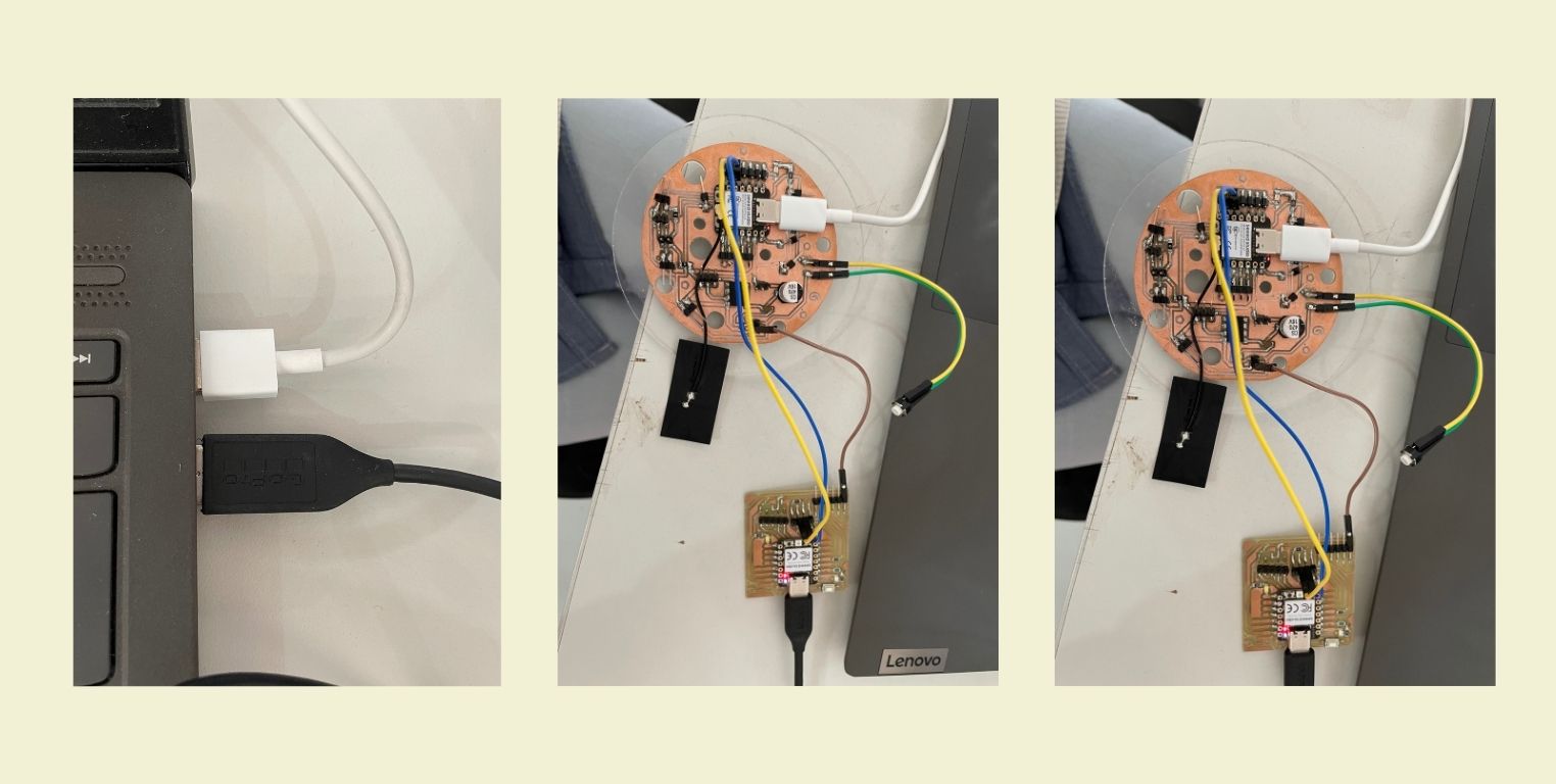
At the moment of connecting SDA and SCL, the schematic drawings of each of the boards were very helpful, as well as the diagrams of each of them.
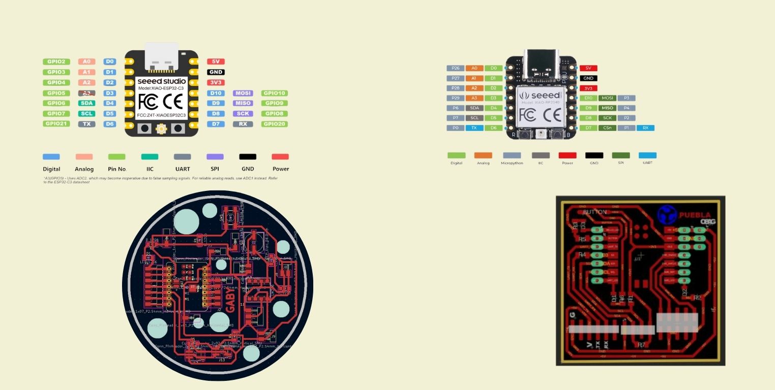
Here a little picture of how everything was connected, SDA, SCL and GND. I quickly asked ChatGPT if the voltage didn't have to be connected as well, but he said no, that both boards must have their own power connection, in case I had used a microcontroller without USB-C connection I probably would have connected voltage.
Before continuing, there is something basic to understand, and that is that for slave and master you have to make a different code, each with the respective indications, I tested the XIAO RP2040 as master and as slave, likewise with the XIAO ESP32C3.
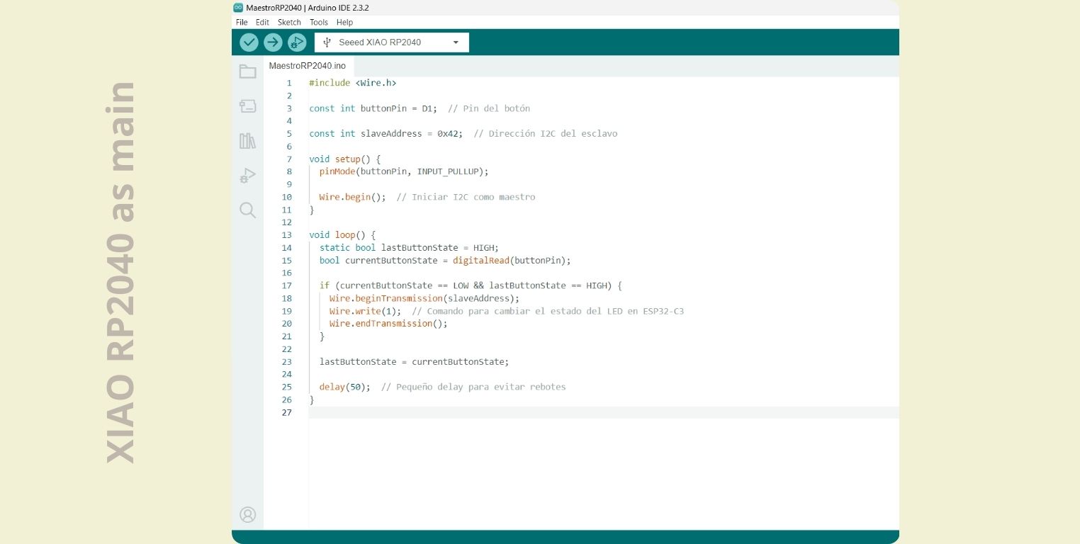
XIAO RP2040 as master and XIAO ESP32 as slave
For the XIAO RP2040 as master I first included the Wire.h library that will help the communication, and I indicated the pin to which the button would be connected, followed by the slave address, 0x42 in this case. In the void setup I declared the button as input, followed by the wire.begin indication to start the I2C connection in which it will act as master. In the void loop what it does is to read the state of the button, and in case it is pressed, then send command 1 to the ESP32C3 so that it changes the state of the led.
In the case of the XIAO ESP32C3 as a slave I included the previously mentioned library, besides indicating the pin to which the led is connected, as well as the direction of communication. The difference comes in the void set up when the LED is declared as output, in addition to indicating the state of the LED as off until before receiving a signal from the master. In the void loop it identifies the command that the master is indicating, and it is given the condition that, if it is 1, then it changes the state of the LED.
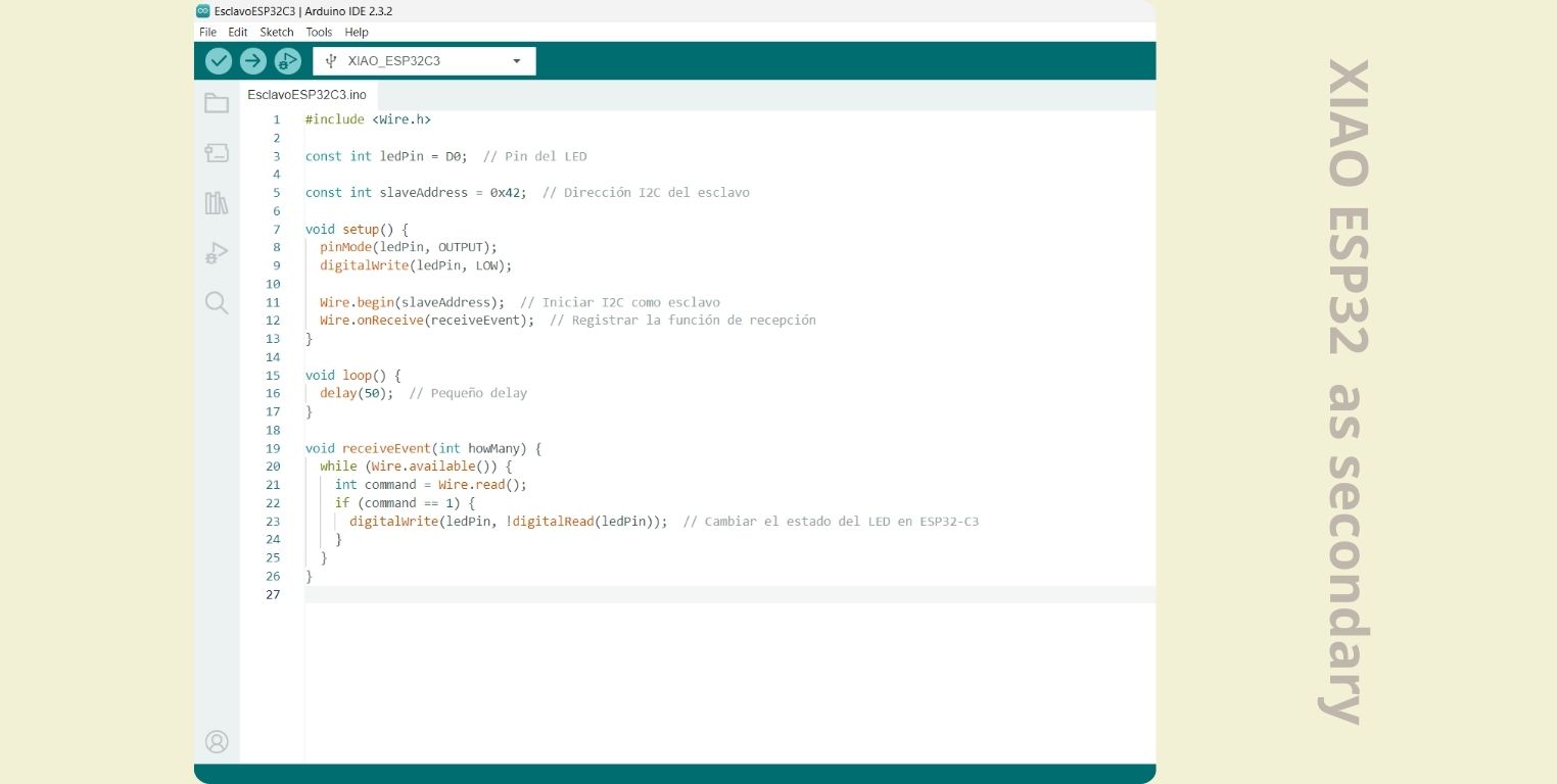
The codes being different for each one, they are uploaded separately, and after both have been programmed you can test them, here a small video.
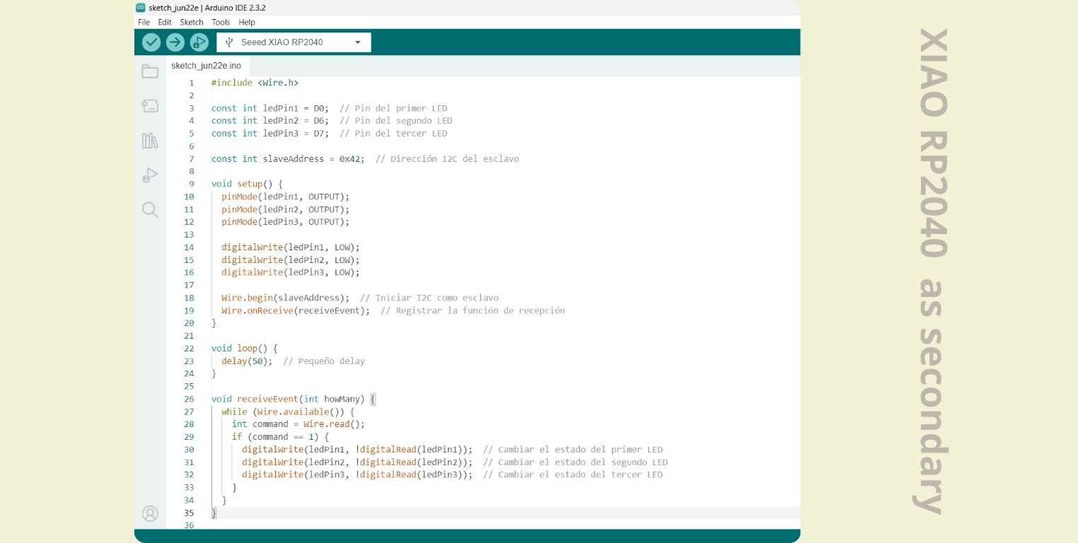
XIAO ESP32C3 as master and XIAO RP2040 as slave
Now I did the same, but reversing the roles of the boards, in the case of the code for the master, this was practically the same.

The most drastic change was in the slave code, in which I added the other two leds that were connected to this one, but it was not really a big deal, I just declared them separately to make the code clearer.
Here is the video of the result.
Conclusion
To tell the truth, this week I saw it very difficult, and more because since we had the class and did the group assignment I let some time pass until I did my individual assignment as such, and although it was something very basic for me it is already quite amazing to see how the two boards interact with each other. In fact, I would have liked to try having some sort of connection of this sort with my final project, however, due to time I could no longer. Hopefully in the future I can continue to explore and now with different types of communications, without letting the pins stop me.