WEEK 5
3D SCANNIG AND PRINTING
This week is about 3D printing, but first what is 3D printing?, we can say that it is a way of production by addition, and how is that done?, well, practically you put a thin layer of material on top of another to completely build the object. In this way you can easily and quickly obtain objects that with other types of processes would be very time consuming, difficult and expensive; in addition, although there are many materials in which it could be printed (from resin to a mix of wood fiber and PLA), the most common is the use of PLA (or some other type of plastic), which makes it a fairly affordable process compared to traditional ones.
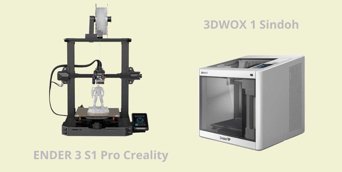
In FabLab Puebla we have different types of printers, but for my specific delivery I used 2 types in particular: an Ender 3 S1 Pro Creality and a 3DWOX 1. I invite you to see the specifications of both in the link of the group practice. And although I didn't take those printers as a reference for the design of my print, I thought it was relevant to mention it.
Doing something that can't be done subtractively?
At the Universidad Iberoamericana Puebla we are educated always taking into account the social aspect, and with it also the impact we can have within that same context, so this particular assignment reminded me of the professors who taught me that every process has a purpose, and we must take into account what we use them for, that way we ensure that we do not generate extra waste, or spend clean energy on something without much sense. But what's the point of all this, because this week I had to print something in 3D that could not be manufactured subtractively, only additively, it is a big challenge, but it also reminded me that you have to know how and for what you use technology and certain processes, as well as being aware and responsible with it. As Dieter Rams says, "good design respects the environment", so we have to be aware of how we produce in order to contribute to the conservation of the environment.
With this in mind, I wanted to design something that I could use without much trouble. At first I thought of a Fidget Toy that I could use for my anxiety, but upon further thought, I realized that I could make my own jewelry. I'm a big fan of accessories, and while for some it might not be useful, for me it's a form of expression, wearing jewelry is part of me on a daily basis.
JOIN ME TO DESIGN!
There are important aspects to take into account when designing a 3D model that will be printed later. Some of the ones I learned during the group practice were the following:
-
To make a hole you must take into account that it must have a minimum diameter of 0.2 mm for it to be made without any problem.
-
If you want the pieces to rotate, they must have a minimum of 0.3 mm of separation between each one, otherwise there is a possibility that with the heat of the layers they will stick together.
-
There is something called "overhang", and it refers to the distance a piece can hang without deforming, the longer and less supports it has, the easier it can be to deform. Actually, it is solved with design because you can use chamfers or roundings that take this into account and provide support to the composition. Although we can also add supports in the program that is set up for 3D printing.
My design process consisted of modeling a pendant for a necklace and a bracelet, both processes in Rhinoceros, because it really is very easy to create organic shapes, and I wanted to play and try a little.
Let's start with the pendant!
When I knew that I wanted to make a spiral structure in a general circular or oval shape, I remembered that a friend in the past had made the model of some earrings with this principle, and on that occasion she told me that she had done it with a YouTube video, so I gave myself the task of looking it up. Now, looking at it from the future I think I made a good decision because it helped me to reduce some time, and for someone who is doing a project for an association and his thesis at the same time as the FabLab, time is really precious.
Here are the general steps I followed for the elaboration of my design. I actually modified it continuously (you'll see why below), but if you recreate it from scratch, take into account the tips I'm leaving at each step (I wish I could have read this before).
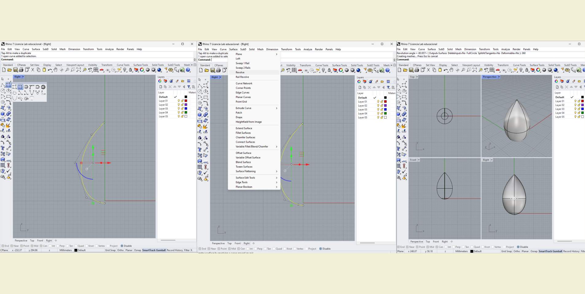
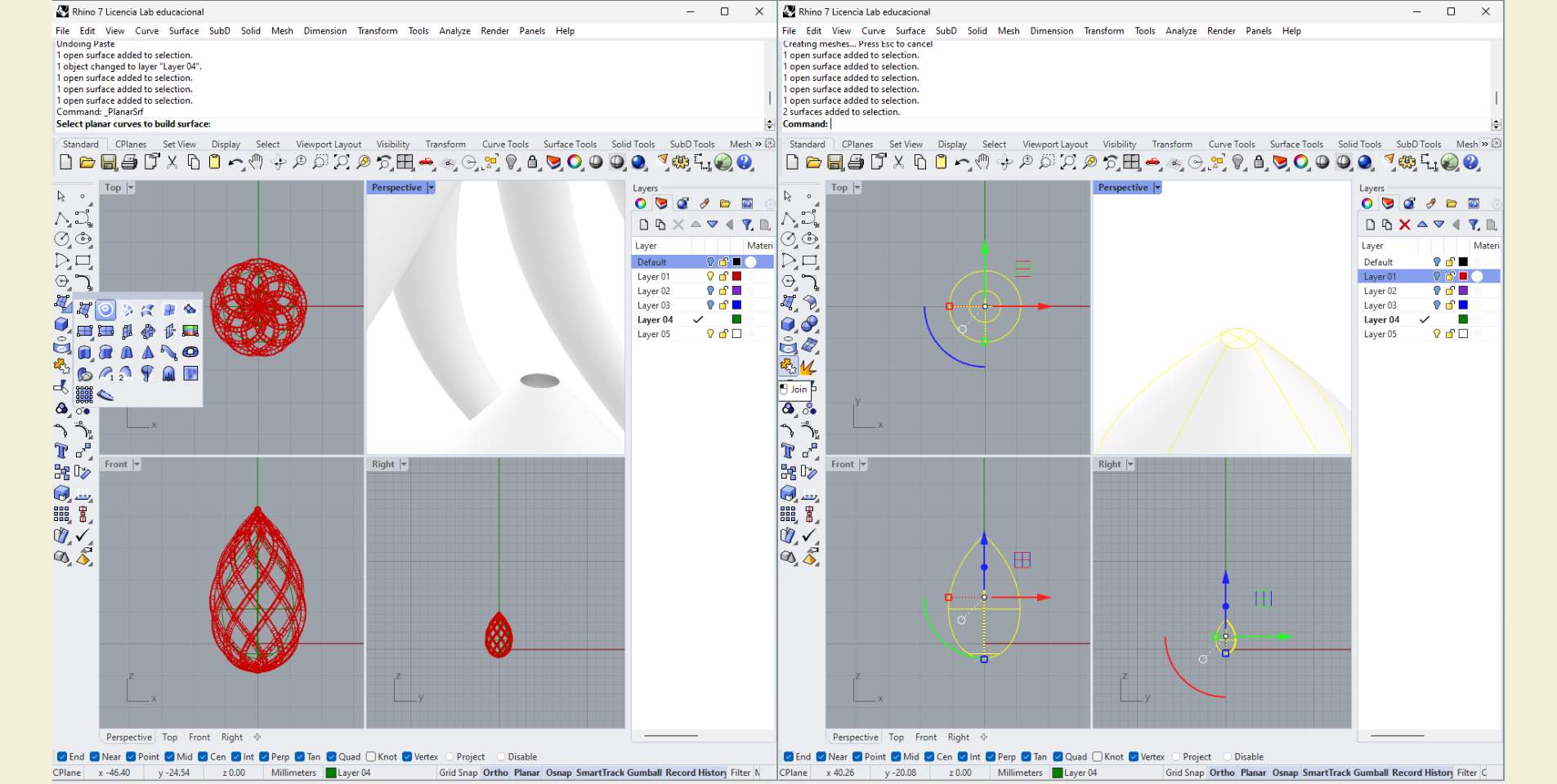
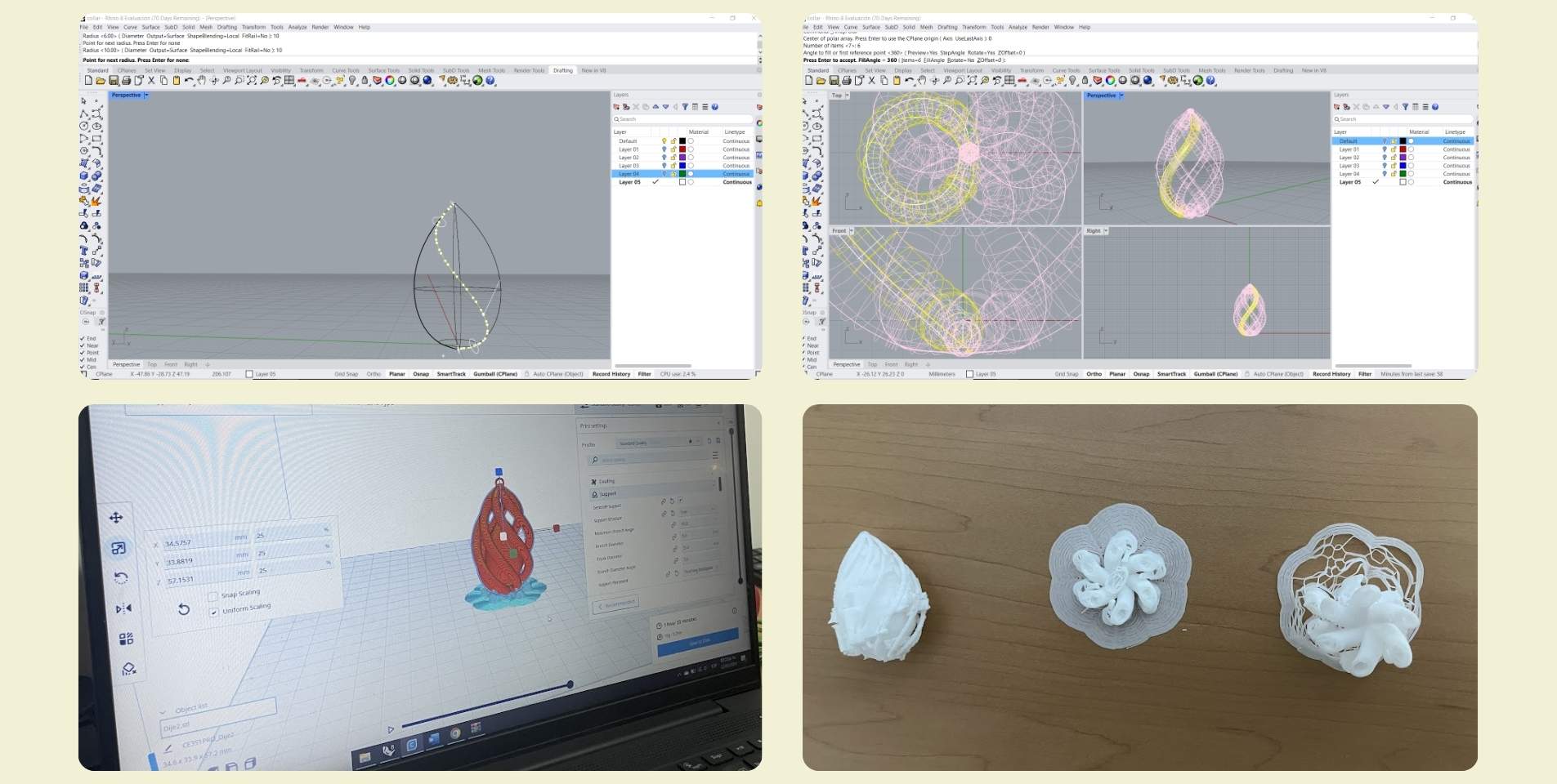
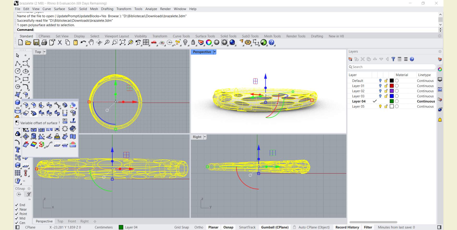
In a new file, from "Small Objects millimeters" (before you start, take into account that you can do everything taking into account the dimension you want at the end for your piece), the first thing is to draw a curve. This curve is going to be revolutionized, so you have to think that, from a side view, it can be seen as half of the overall piece. In this case I followed the shape of a drop of water, I didn't think much about it. Then I revolutionized this same curve with the origin at 0 (this is because the curve I drew was as close to the origin as possible, in the modeling it is practical to have everything centered at the origin) and at 360° to have the base and general surface of the shape I wanted the pendant to be.
Sometimes it happens to me that I don't see the surfaces, and it is because you have to change the view type, not in all, generally only in Perspective you can change to "Shaded" or "Rendered".
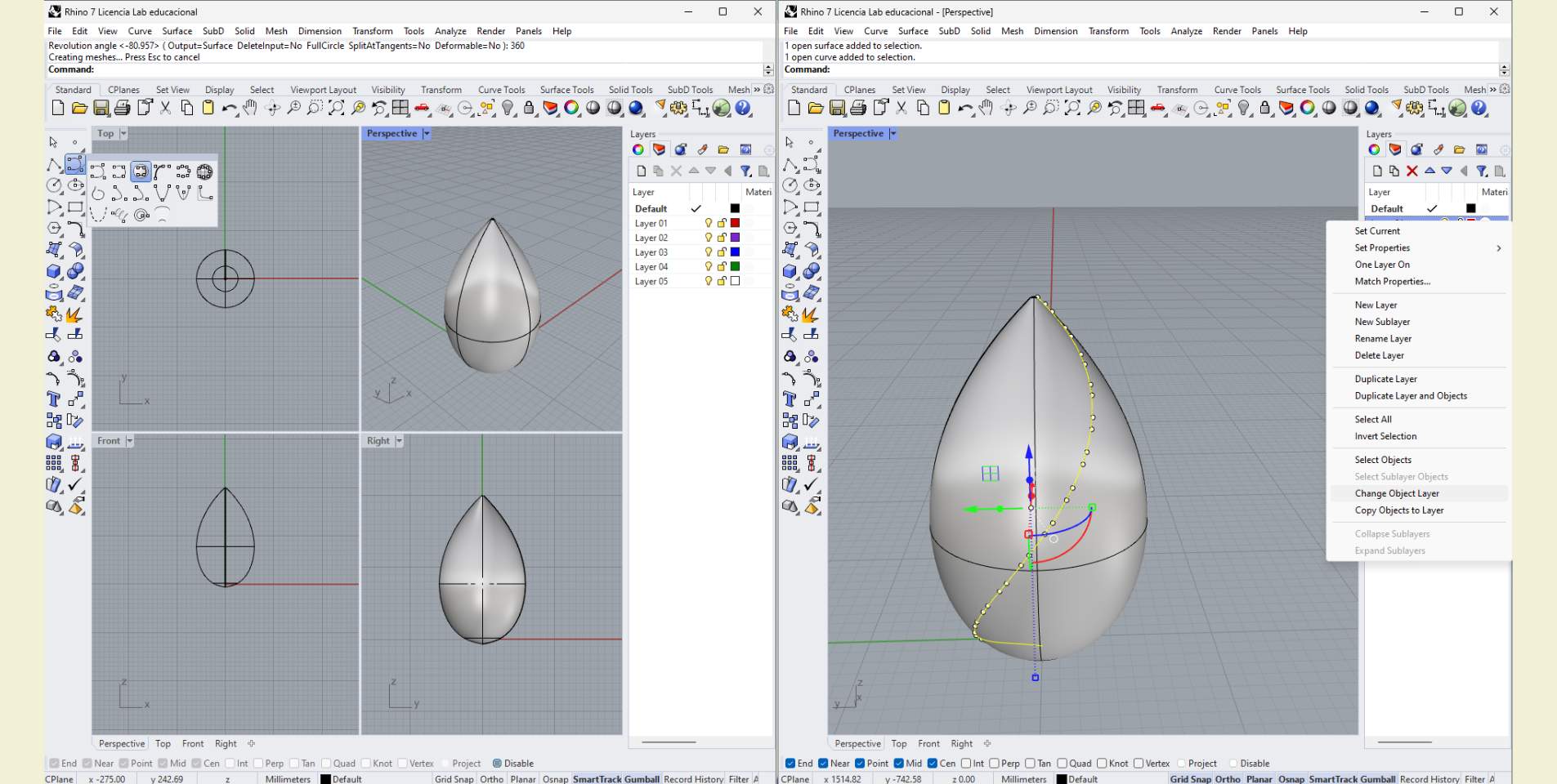
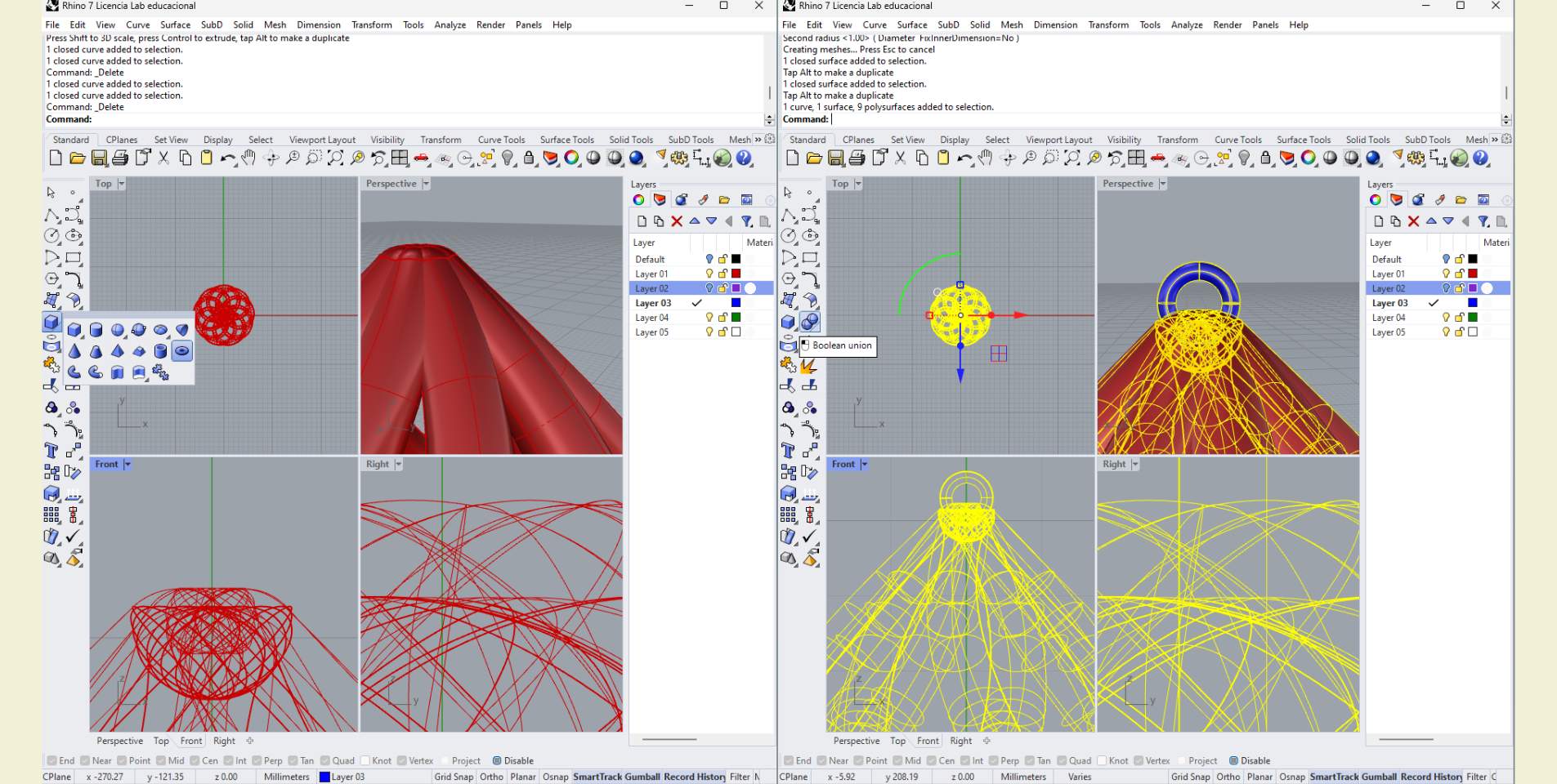
The second thing was to draw an "Interpolate surface curve" from end to end of the surface I did before, so that I got a curve that has a spiral shape. Then I selected this curve and changed it to another layer, and left visible only the one where I changed my curve.
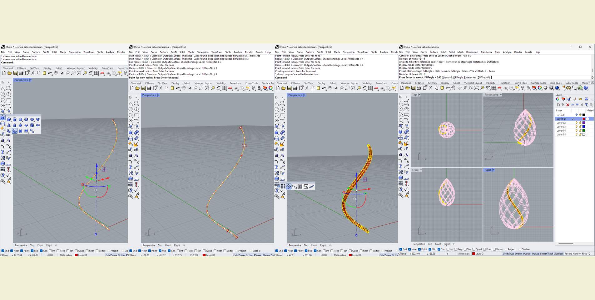
What I did with this curve was to make a "Pipe with rounded tips". And as at the beginning the truth is that I was not making it to original scale, I just made sure that the dimensions of the ends were thinner than the rest of the body, for example, in the pictures below you can see that the ends had a diameter of 3, while the rest of the body had a diameter of 4; maybe it is not a big difference, but I thought it was enough, I would not recommend such a big difference in these values so that the structure is perceived uniform and not so drastic. Once ready what I did was an "Interpolate Matrix" with center at 0, at 360° and a number of items between 6 and 9 (this was calculated according to the thickness of the Pipe, because the thicker it was the less showy it looked with more items and vice versa. Why I don't just say the exact things?, well because I modified it several times. In fact, in my original file you can see many layers that I made with the modifications, but as these modifications I made for the print proofs, let's not get ahead of ourselves yet.
The next step was to make the eyelet for the chain to enter. For this I used the "Toroid" tool. In the photos of this step you can see that I did not make it so big, in fact, it is thinner than the spirals that form the drop structure for the pendant, however, it is advisable to make it as wide as possible so that it can be printed without problems. The next thing I did was to apply a "Boolean join" to everything.
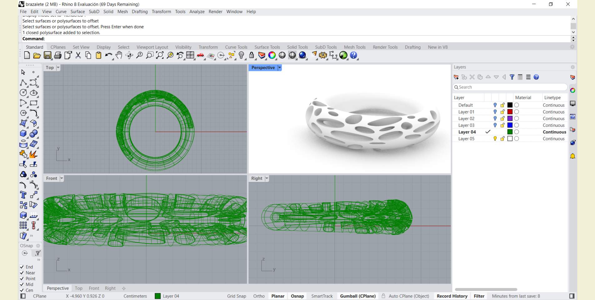
Now that the piece was almost ready, what I did was to scale it in 3D to the size I wanted. To do this I made sure that the overall width of the piece did not exceed 3 cm for two reasons, the first is to take care that it is small for a necklace, and second for the time we had to print per person, in the FabLab Puebla we are many, so we had a limit of 2hrs printing time, so I had to take into account that printing also takes time and therefore could not be too large.s
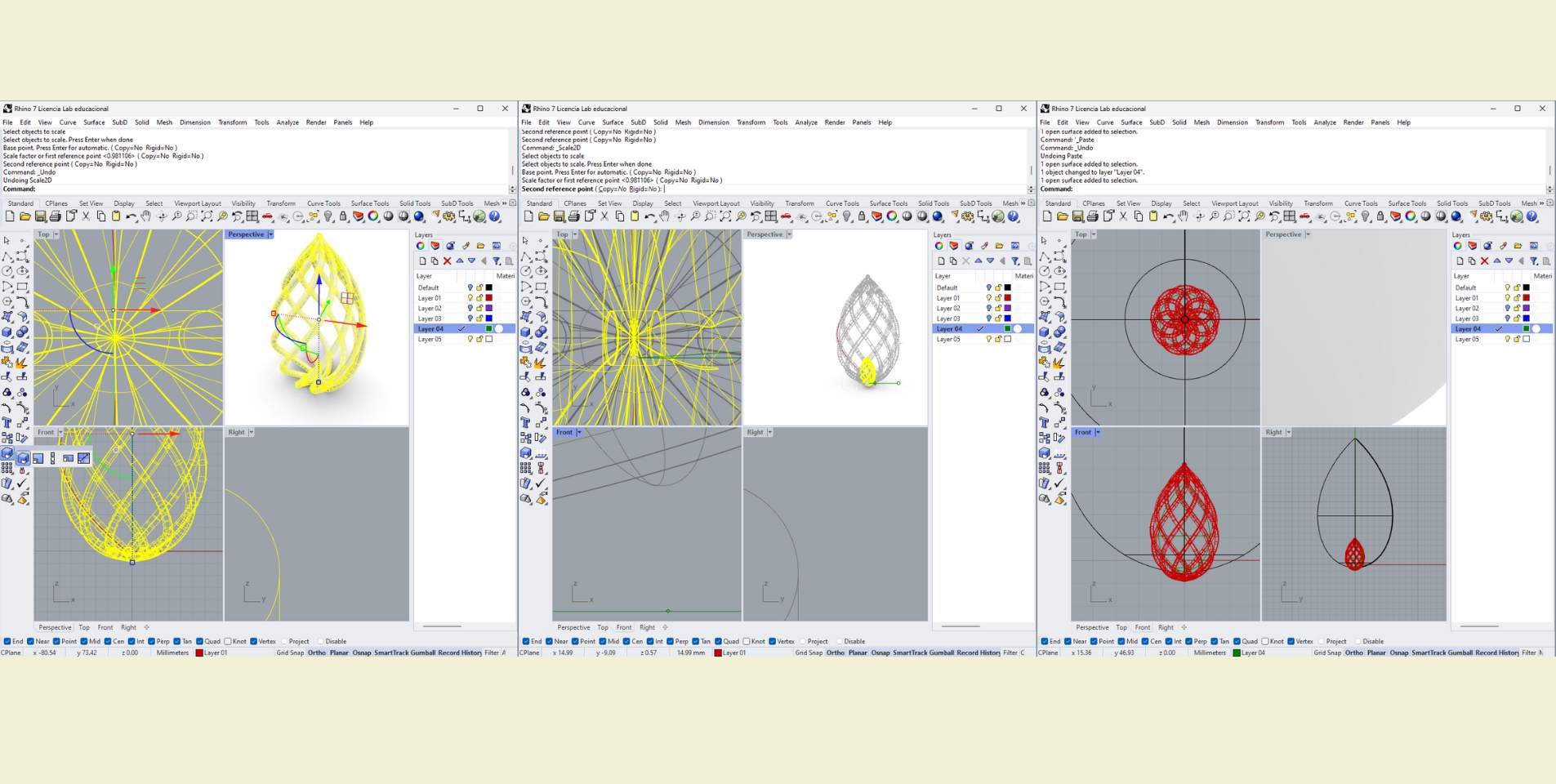
When it was almost ready I thought it might be a good idea to have a little drop inside the whole structure, it was a nice detail. So what I did was to copy the main surface and then reduce its size to fit, and the next thing I did was to cover the holes that the surface had with a "Patch". This step can be made easier with a sphere, and you could modify the shape to make it look like a drop, in fact, this is what I did in the end, I just didn't modify the sphere.
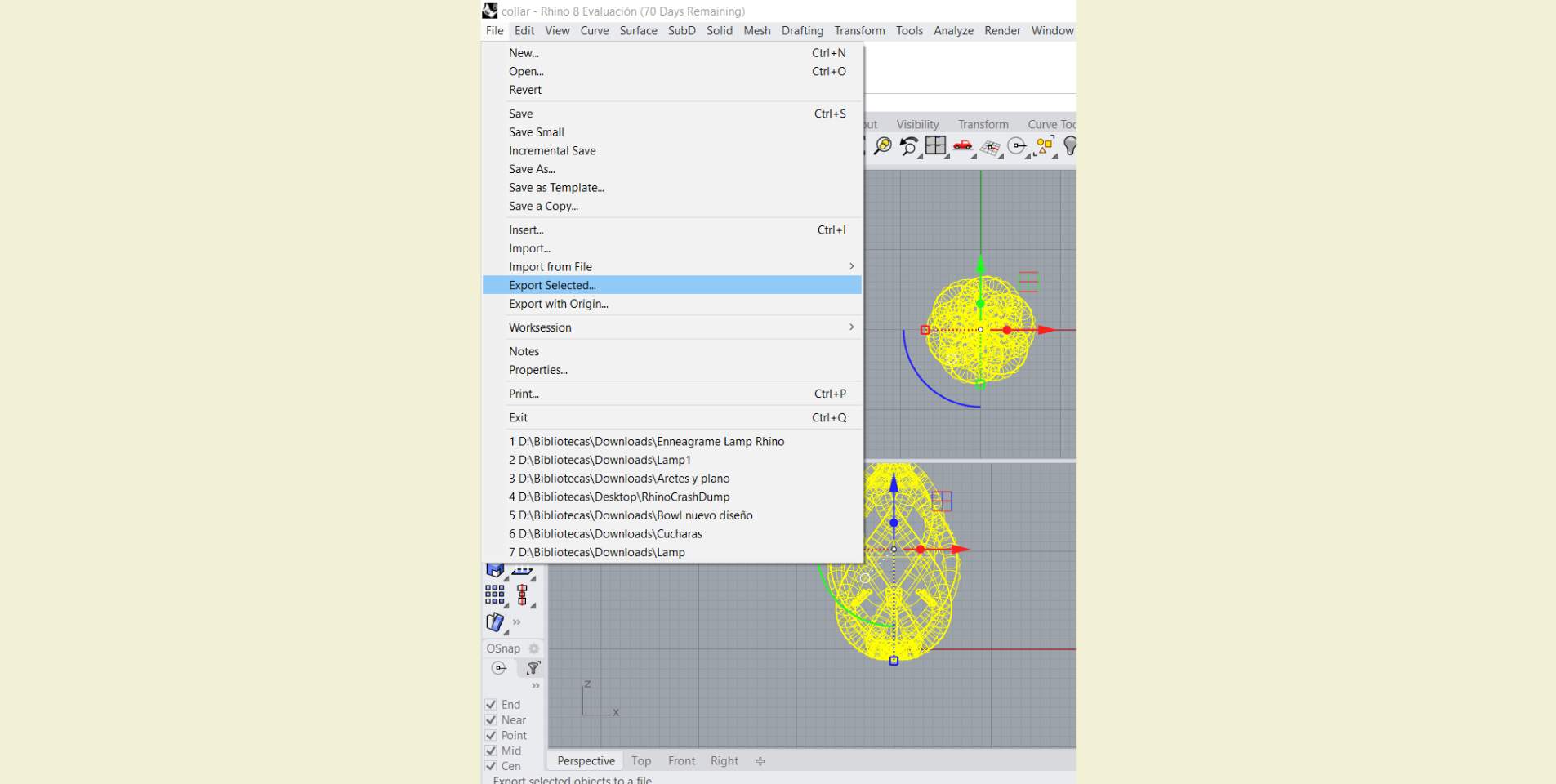
And well, the last step is very simple. Once you select the complete part the program tells you that you are selecting a solid, then you can "Export selected" in STL format and then pass it to a 3D printing configuration program.
LET'S CONFIGURE WHAT WE NEED FOR PRINTING!
For this process I used the  UltiMaker CURA
program, a free software compatible with a wide variety of 3D printers that allows you to configure
your prints so that they can go from the digital to the physical plane. It's not too hard to figure
out, in general it can be quite intuitive, but I would say that it does take some time to play with
all the tools to experiment and learn.
UltiMaker CURA
program, a free software compatible with a wide variety of 3D printers that allows you to configure
your prints so that they can go from the digital to the physical plane. It's not too hard to figure
out, in general it can be quite intuitive, but I would say that it does take some time to play with
all the tools to experiment and learn.
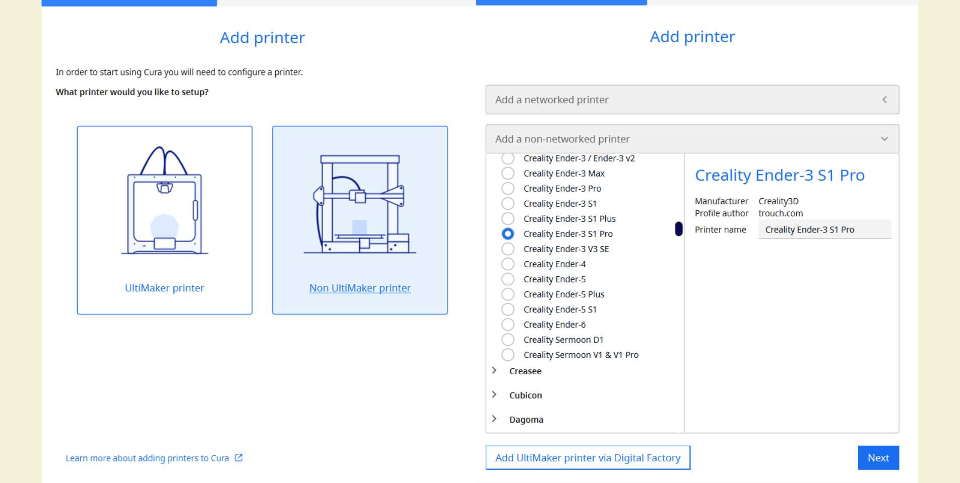
The first thing you have to do when using CURA is to tell it the printer you are going to use, in the case of FabLab Puebla we told it that it was a printer that was not connected to the internet and we chose the Ender 3 S-1 Pro printer.
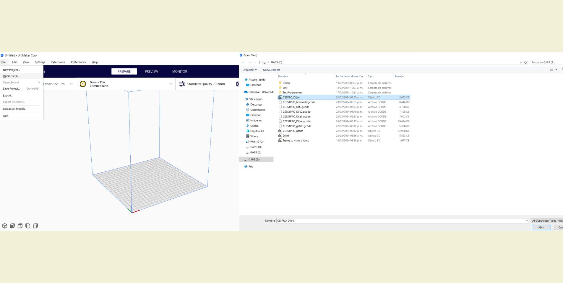
Another basic to start is to know that to open a file in CURA is as easy as going to "File" and click on "Open File(s)". So there is no loss. And not only do you have to take into account the printer you are printing on, you also have to look at the type of material you are using, that is selected next to the printer.
How do you determine the quality of a 3D print?
During the group practice I learned that this concentrates a very large set of characteristics (all configurable in CURA) that you have to take into account, some more, some less. Below, I put a table with some important features that can be taken into account for this step.
| Quality | Refers to the height of the layer | It is not recommended to exceed 80% of the diameter of the printer nozzle because then the layers could not stick. |
| Walls | Refers to the green and red lines that separate the outside from the filler | If sanding, do not do less than 2. |
| Top/Button | These are all layers parallel to the print bed. Roundings also enter here | For this reason it is recommended to activate "Enable Ironign" because it leaves a smoother finish on those parts. |
| Infill | Refers to the fill density and pattern parameter of the part | Don't go over 50%, that's really enough to have a solid part. |
| Material | It is the specific area to adjust the printing temperature and the printing bed temperature for each material | It is essential to change the parameters depending on the material to be used. 6 |
| Support | Refers to the supports that are put on the piece to hold it during printing | For organic pieces with difficulty to enter it, the tree support is recommended because it is easier to remove, but in general the regular support is recommended because it is faster, but it is somewhat difficult to remove |
| Clerance | It is the space between the support structures and the printed | You should hace a space between 0.2 mm to 0.5 mm |
ASPECTS TO KEEP IN MIND
- Always print on a flat side, or as flat as possible to have a good base.
- You have to change the parameters for each of the materials.
- For conical structures it is recommended to make the last layers cooler.
- Within the Infill patterns, "line" is the most optimized and fastest, while "cross 3D" is for flexible parts.
- If "Enable Retraction" is activated, printing defects such as the "hairs" that sometimes remain can be eliminated.
With the above table and list you can start setting up your first prints! I really recommend a lot of testing, time and as I said weeks before, think that it will take you twice as long (sometimes even more).
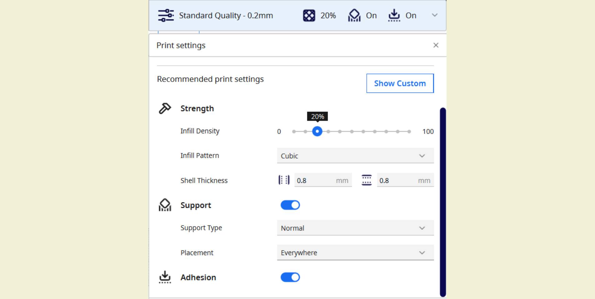
My first test with CURA during this week was very fast, I had help and everything was very express, and so they made me the suggestion to use the general recommended parameters of the application, something that could work, but it is also good to play with each parameter yourself.
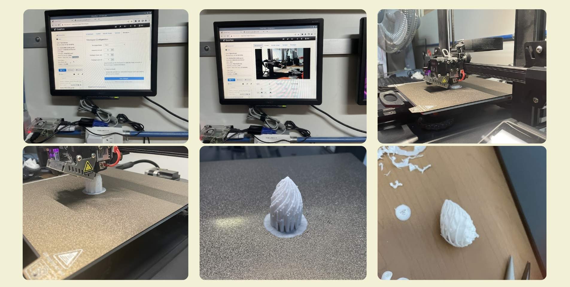
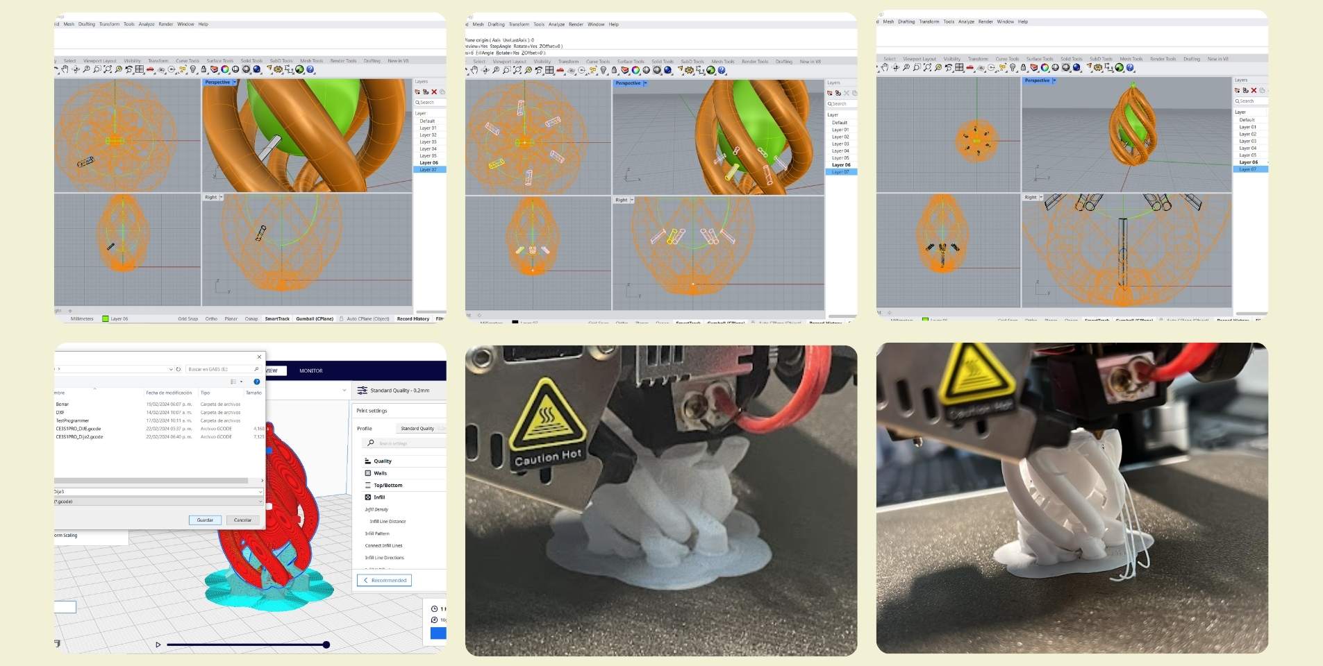
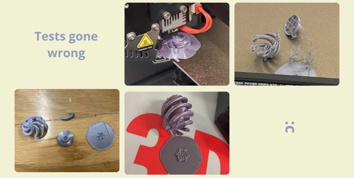
Going ahead a little bit about the impression, it started well, and the truth is that it was quite fast, in half an hour I was already there (but to cry :c). The truth is that this first impression was not his fault as such, but mine. When scaling my design I did not take into account that the thickness of the structures that form the drop would also decrease, and in fact I think I even had enough that they were printed, however, the eyelet for the chain at the beginning I had made it smaller, so it did not come out in the print. Another aspect was the fact that I used a regular support on everything, this helped the printing to go quickly all the way through, but when I removed the supports this was almost impossible, and the external structure started to break before I removed all the support, so I had to go back to the design part.
GOING BACK TO DESIGN
What I did then was to go back to Rhino, and make the diameter of the "Pipe" of the drop structure larger. And in Cura, instead of using support throughout, I selected "Touching Buildplate". However, this sadly was another fail, because I didn't realize that the drop inside had no support, so there came a moment when the printing had to stop after a while because the drop started to be made in the air... Something super basic, but that I didn't realize until I sent to print for the second time this new file. Up to this point I counted 3 attempts with 2 different files.
So... I went back to Rhino, because I didn't know how to add a support under the floating drop in Cura (I learned how, I explain in the subsection below :D). So what I did was to make my own supports in Rhino, thin enough to remove, but thick enough to come out in the print still. I put 6 cylinders underneath the drop diagonally and one more vertically. That day I really thought I was done and had made it, the print up to the time I left was going quite well; however some time later I got the message that the new print had died again :c (insert sad music), this time it was the top part that peeled off.
-
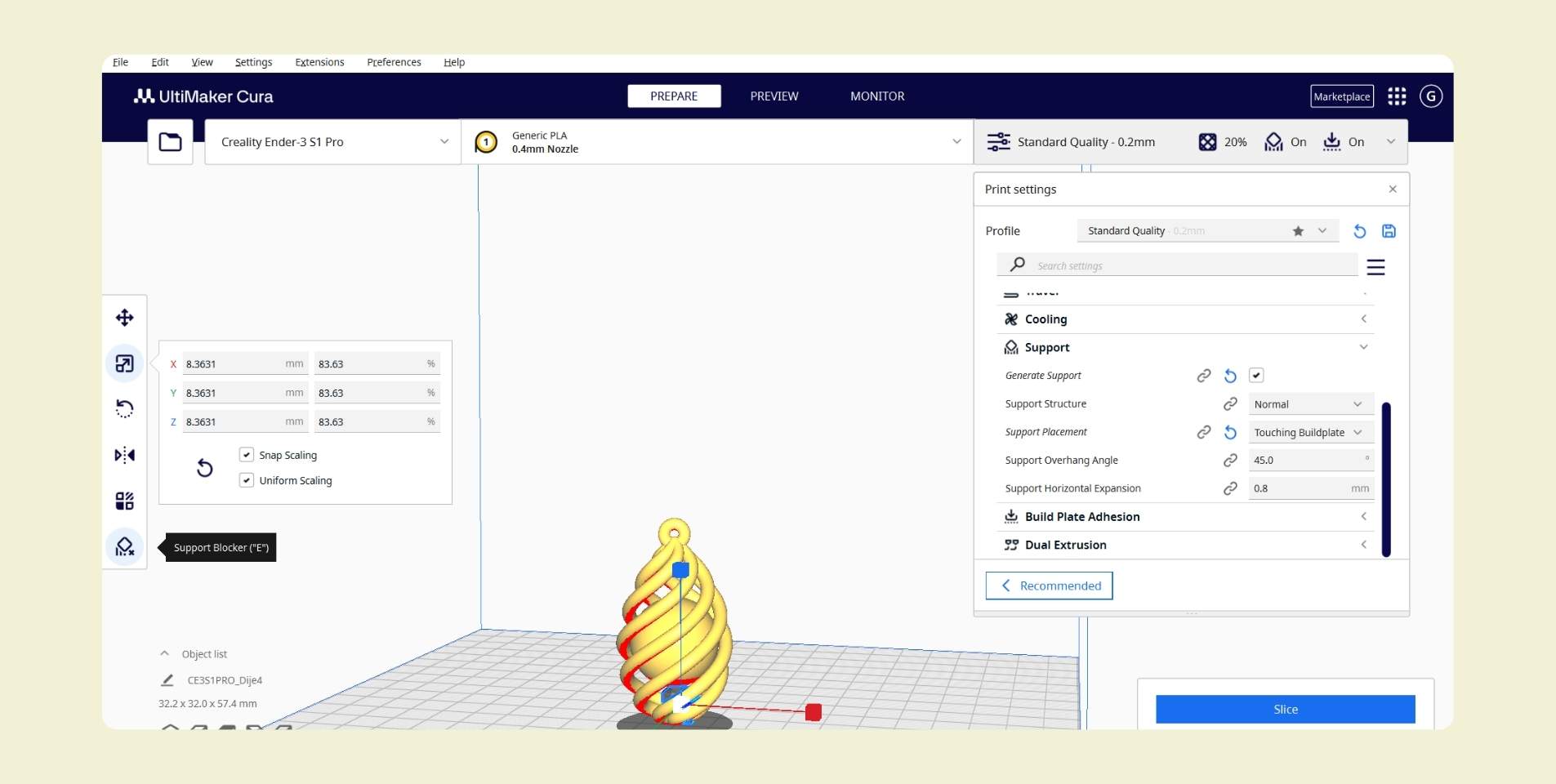
Actually instead of doing what I did in the previous step it could have been solved by selecting my object and clicking on "Support Blocker" and then where I wanted the block. In case you have to adjust, with "Move you can move" and it seems to me that in general the size is default, but with "Scale" you can resize it. Something easy and simple, that I didn't learn until after 4 tests :c
For the next proof I reflected on what had happened with the previous ones. The first print was complete except for the eyelet for the chain, while the others had not finished printing because there were no supports or because the layers were peeling off, and the big difference between these last three tests and the first one was not the redesign in the modeling software, but the support I had used, so I wanted to do my next test with a support on the whole object, however by doing this I exceeded the time limit of 2hrs, and even my advisors told me that the design did not need it because the layers could stand without problem one on top of the other, so the design was already fine.
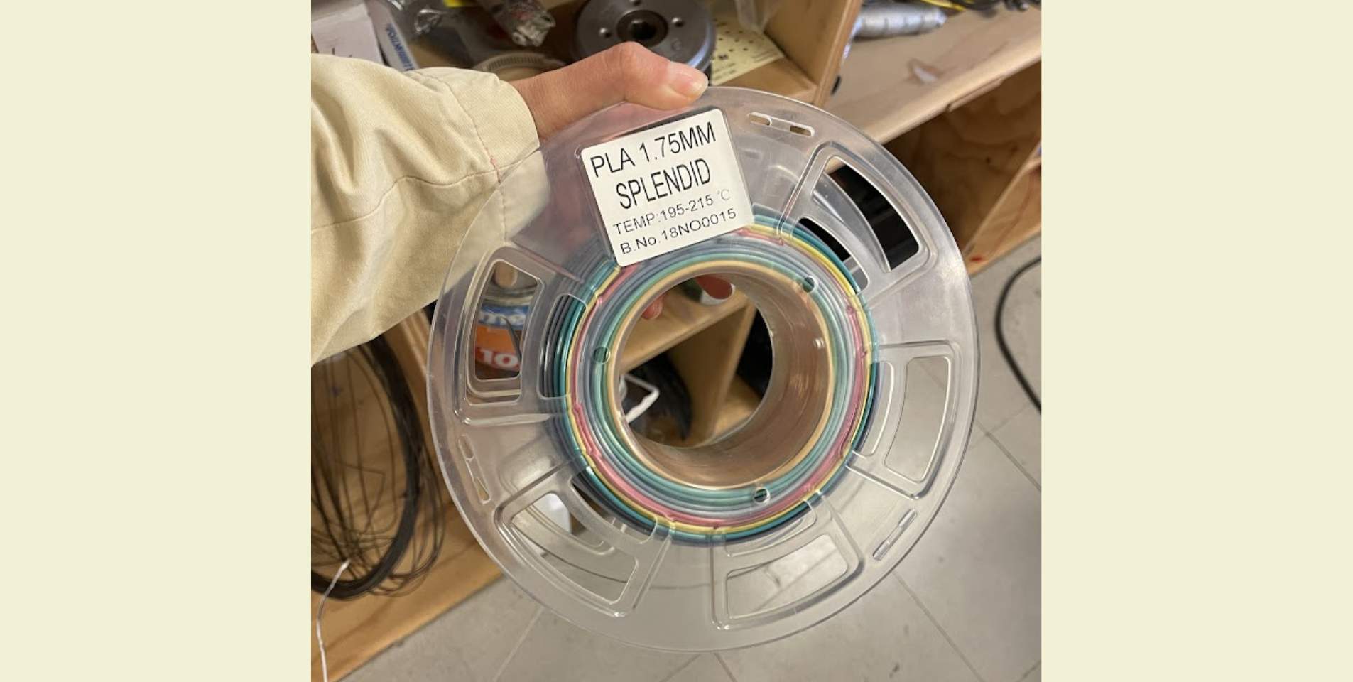
I didn't mention it before, but for the past tests and the following ones I used PLA, the one for the first tests was white, while for the following ones I used a PLA of mixed colors, and I wanted to try it because I thought it could help my piece to have a nice finish.
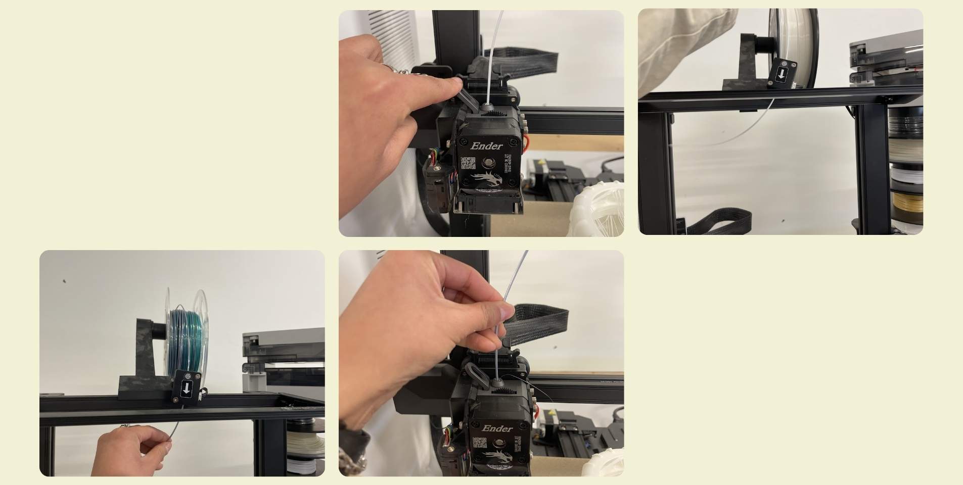
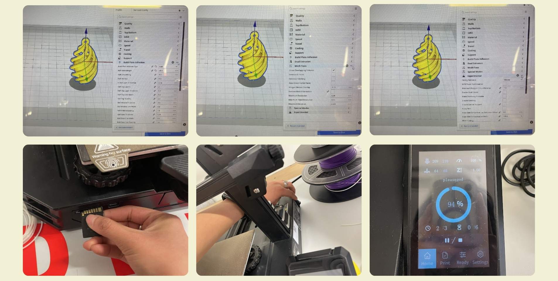
How to change the filament in a printer?
Before I show the following tests and the final result, I'd like to mention that I also learned how to change the filament. I know it's super basic stuff, but this has to go in the right way so it doesn't get tangled and can be managed effectively. When I first changed it it was cold and many hours unused, so I simply removed the filament while pulling the latch. When done after printing this doesn't work as easy because the filament at the tip is melted, but you can still do it from the printer screen and it just ejects it, I really think this is the best option.
Back to the printing tests... This happened on another day, and I really don't have the exact count of the times I tried to send the print again. I got quite a few tips and advice from my advisors, they helped me in every test because it was either peeling off the print bed at the beginning, or the layers were peeling off when the print was more advanced, so here a few things that may help:
 Between each print you should clean the bed with alcohol, and you
should not touch the print area with your fingers because it could get dirty and would not help
the print to stick well.
Between each print you should clean the bed with alcohol, and you
should not touch the print area with your fingers because it could get dirty and would not help
the print to stick well.- It is recommended that if you can not be watching the print all the time, at least one should wait until the first layer is done correctly to ensure that it has a good base and will not peel off in the future.
- Previewing the support in the program is also important, so you make sure that the parts that need support have it.
- Depending on the material and shape of the part to be printed, the speed and temperature must be taken into account. For more complete parts a higher temperature and a lower speed is better.
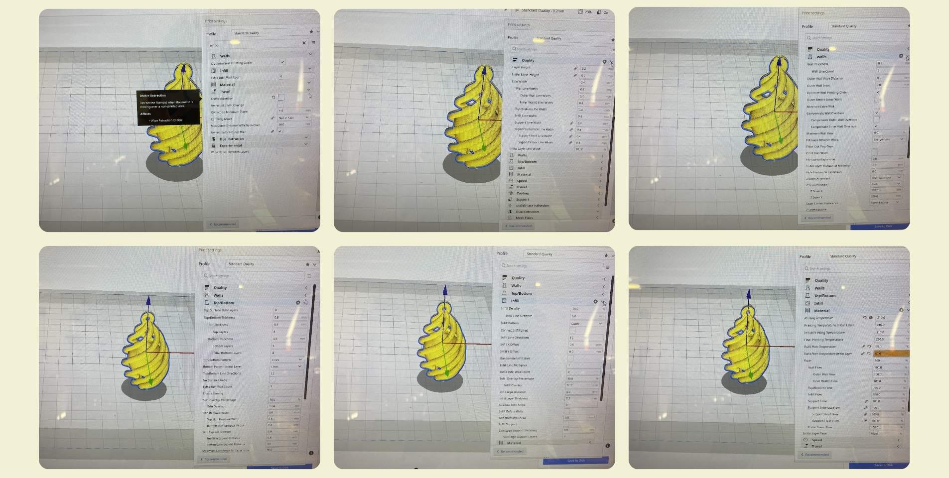
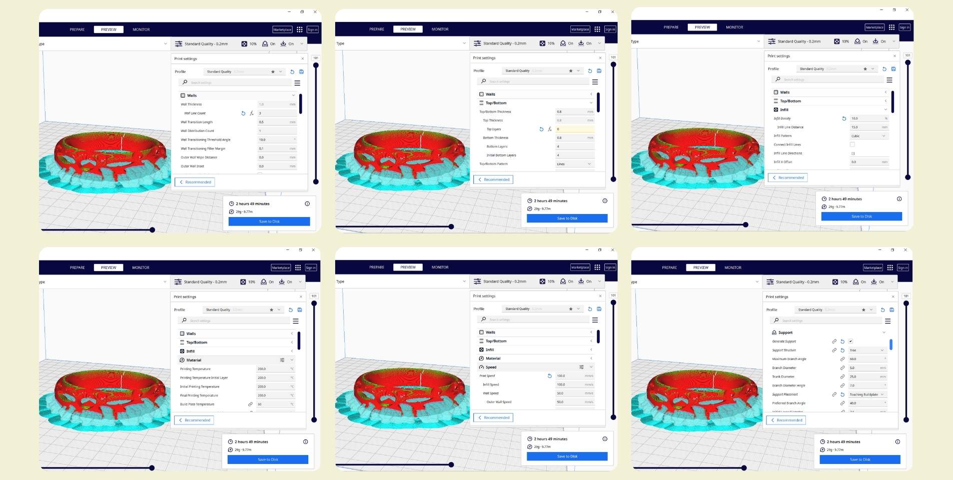
In order not to make a long list, I prefer to attach the photos of the configuration I made for my printing, the final one that did come out.
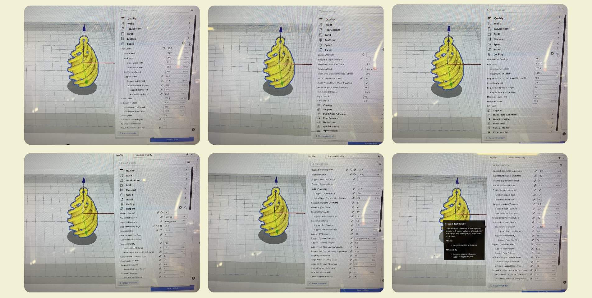
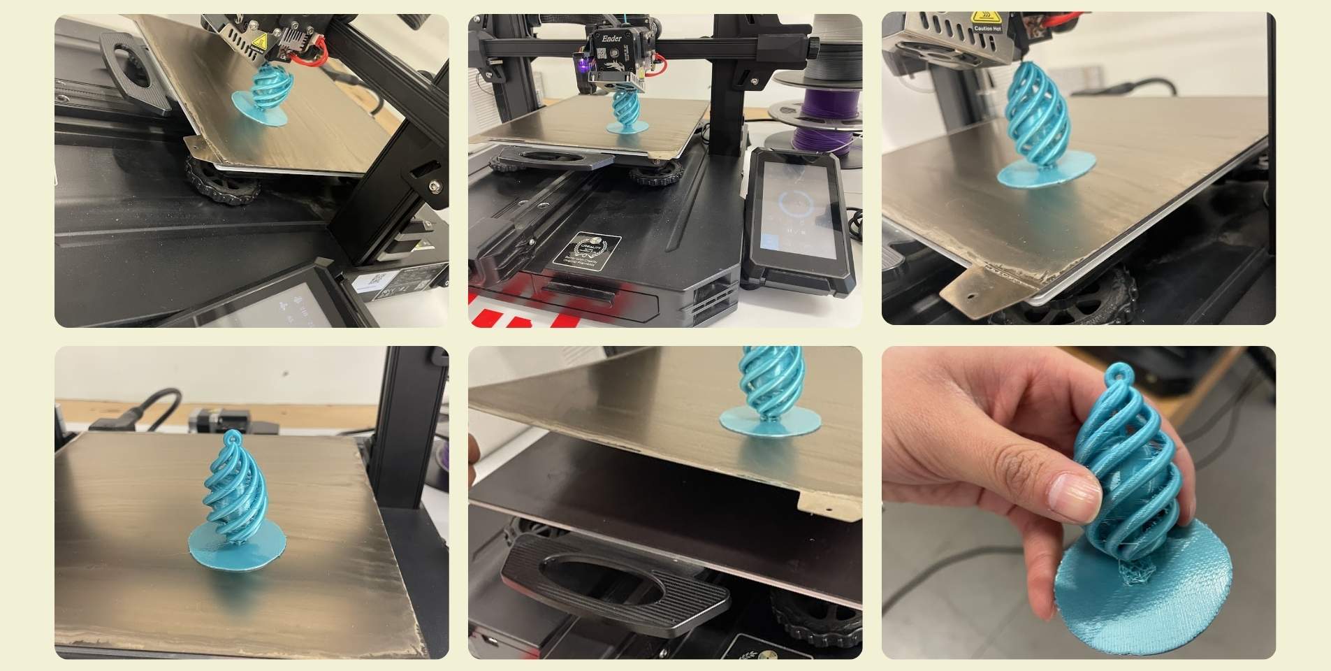
What almost no one tells you is how time consuming it can be to remove the brackets. In fact, with my piece I had a very large one inside holding the sphere, I was afraid of breaking the structure trying to get it out, but in the end I managed to undo the structure inside and get it out in small pieces.
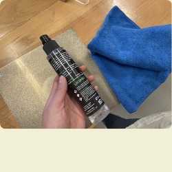
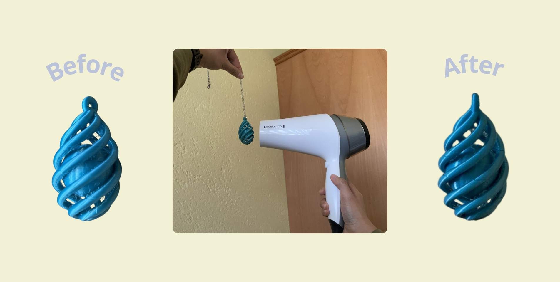
A friend gave me the tip of using a heat gun machine for the "little hairs" that were left on the impression, but many times this is very powerful and I was afraid of melting my piece, so I decided to try using a hair dryer. To some extent it worked, maybe if I had done it for a longer time it would have worked better, but my piece started to feel a bit moldable, so I stopped, but at least I think it improved the finish of the piece.
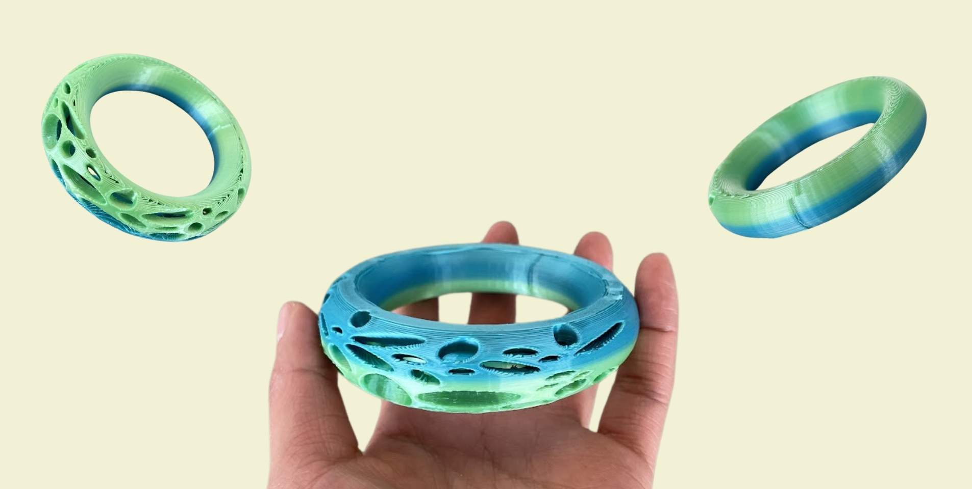
Designing a Bracelet !
The truth, although I had been told that the problem with my piece not coming out (after many attempts) was not in the design of the piece, but in the printing configuration, I started to believe that maybe it was the design, so I started to make a bracelet.
Actually from before I had thought about making a bracelet, but I wasn't quite sure because of the idea I had in mind for its design. To make it I watched a YouTube video where it explains how to make a pattern, project it and then remove the projected surface, I'm sure you understand with the steps below.
The first step actually was to make the shape of the bracelet. It wasn't so complicated, I used base circumference and I gave them an orientation to make a wider part and a thinner part (you can see the base circumferences I made in red in the side views). Then with the "Curve interpolate points" tool I drew 4 curves that touched the 4 key points of the bracelet (you can see it in yellow color). In the meantime I also made the pattern I wanted my bracelet to have and then I could subtract fragments, I think it could have been prettier, but I didn't really think too much about it.
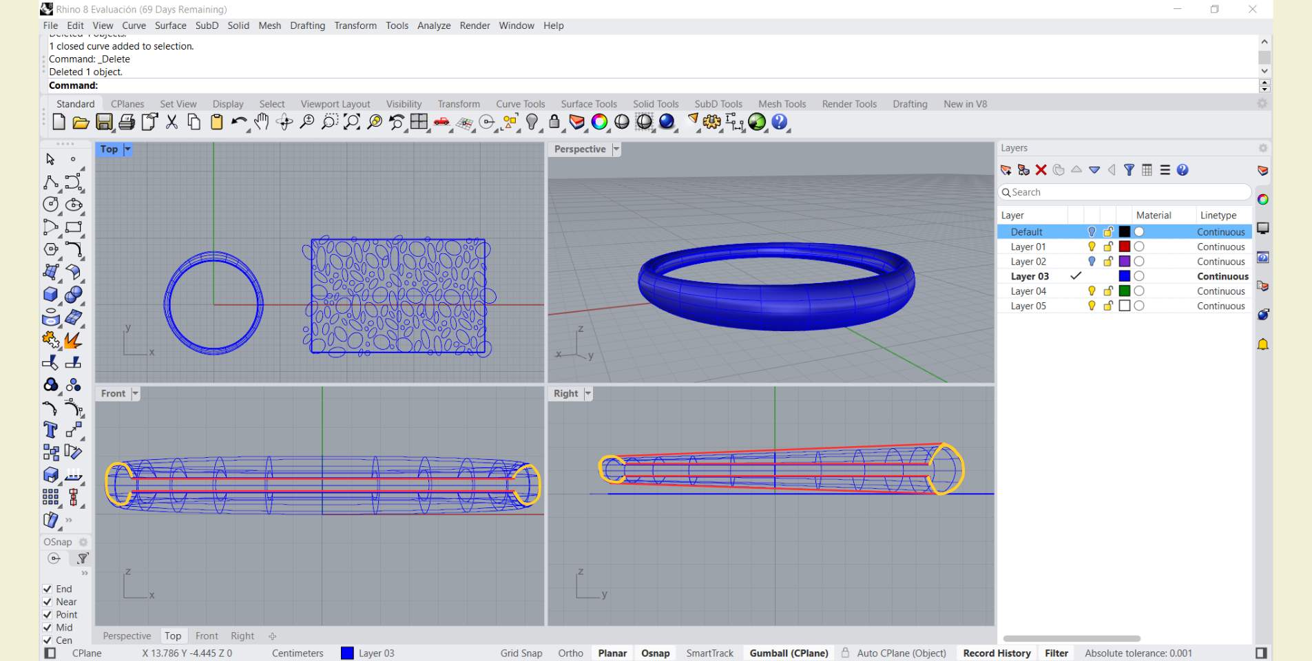
I made the pattern on a rectangular surface, and I took this base as a limit to cut the edges of the pattern that I didn't need with the "Trim" tool.
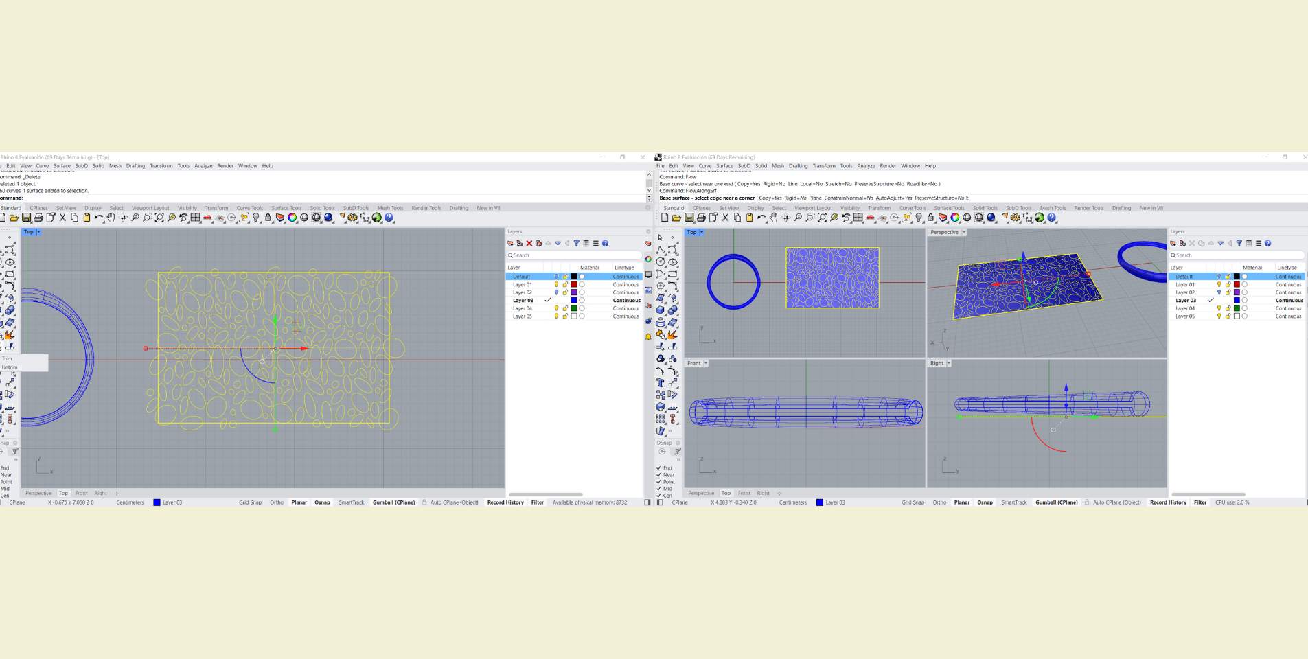
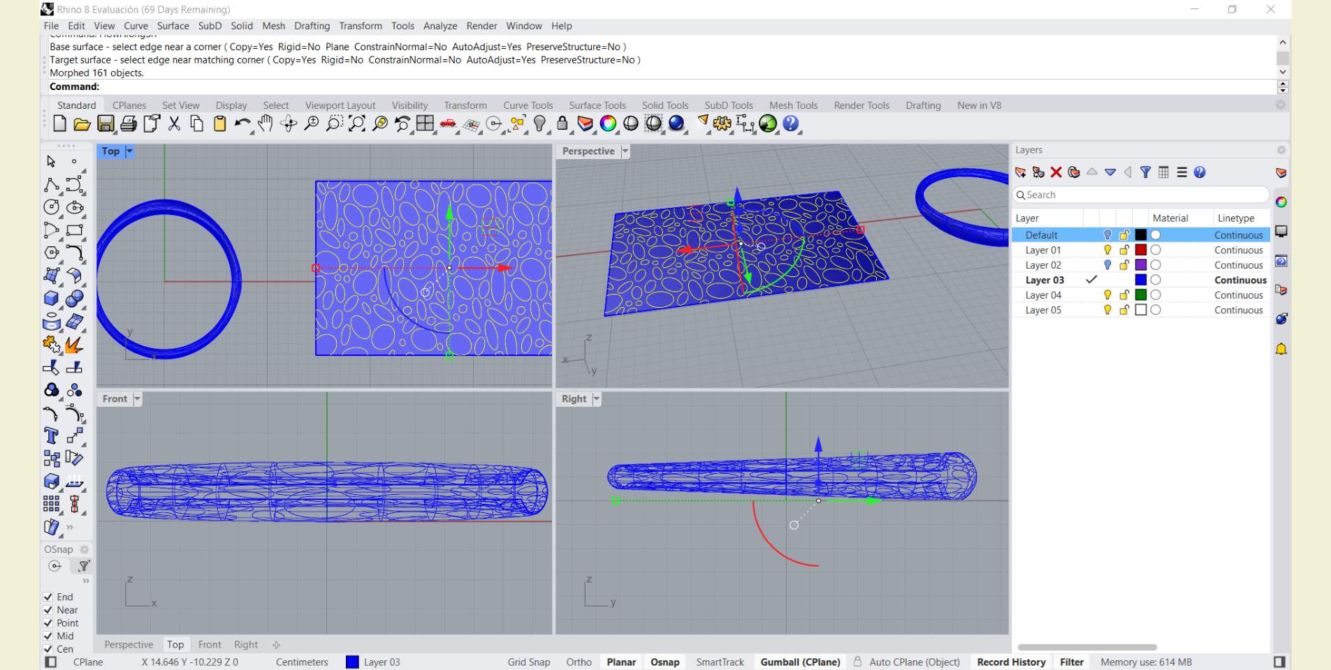
I selected the pattern without the rectangular surface and looked for the "Flow along surface" tool. Once the tool was selected I then selected the rectangular surface and then clicked on the cuff, with those steps the pattern was projected.
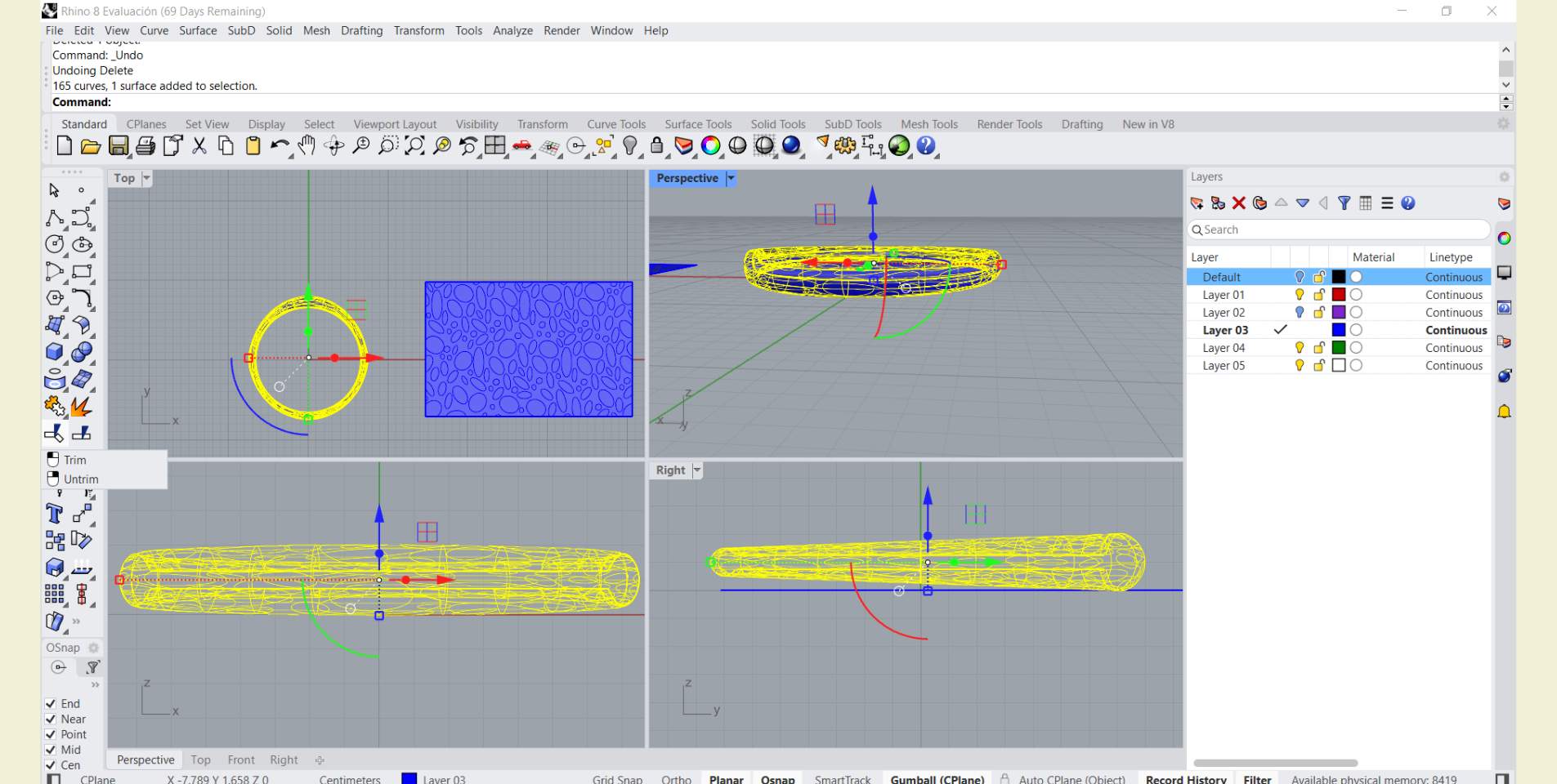
Once the pattern was already on the surface, with the "Trim" tool selecting the pattern I cut the parts that I wanted to remove from the bracelet, so that it was with holes, but also only in the widest part of the bracelet and the rest followed a smooth and flat surface.
Finally, I generated an "Offset" outward of 0.1 mm and activated it to be solid.
Next, I share with you the configuration I used to print this piece and a little bit of the process. It took more than 2 hrs, it was printed in 2 hrs 49 minutes, but as it was the last print of the day I could leave it longer, as there was no problem if there was someone behind me who also wanted to print.
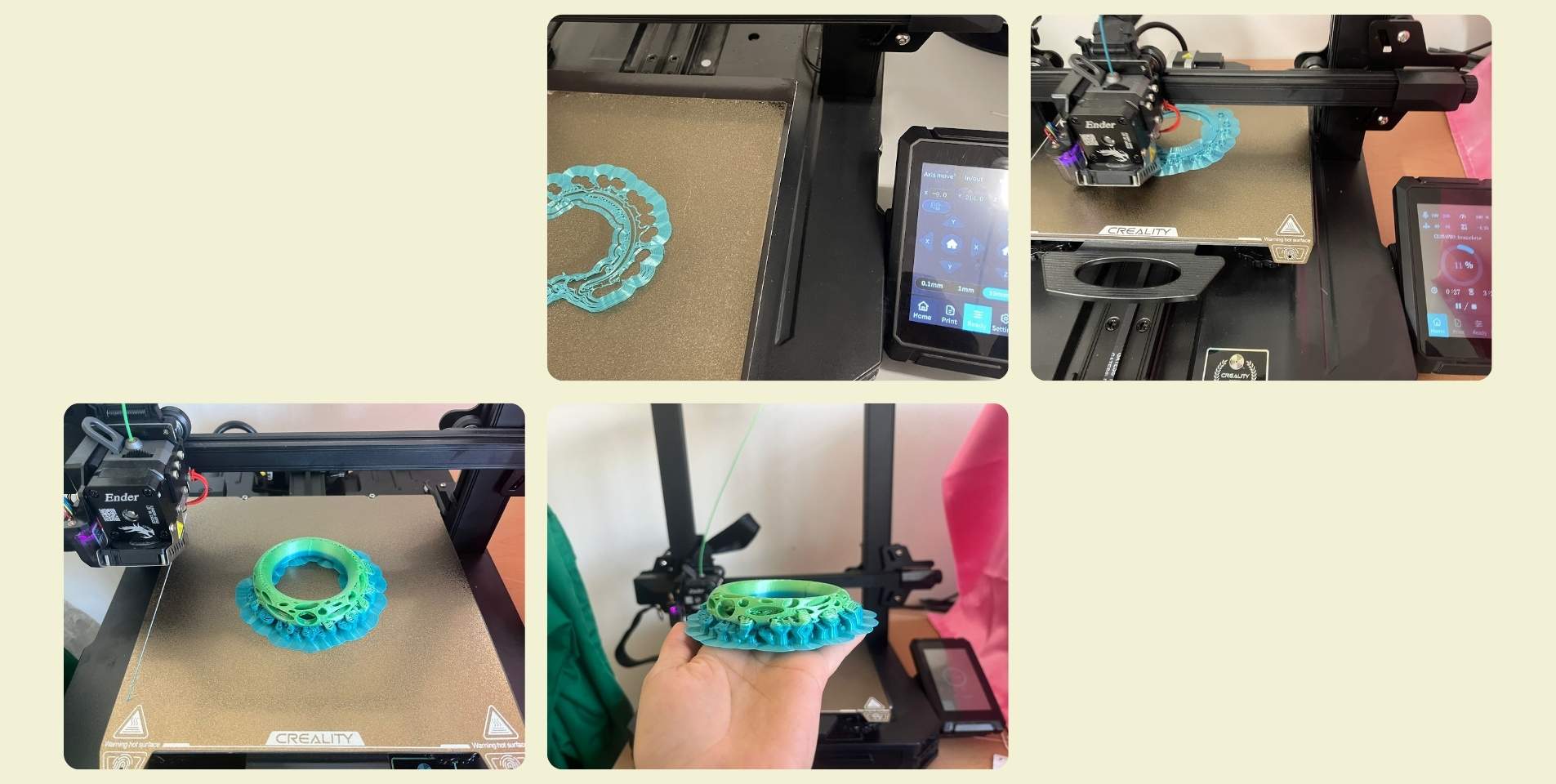
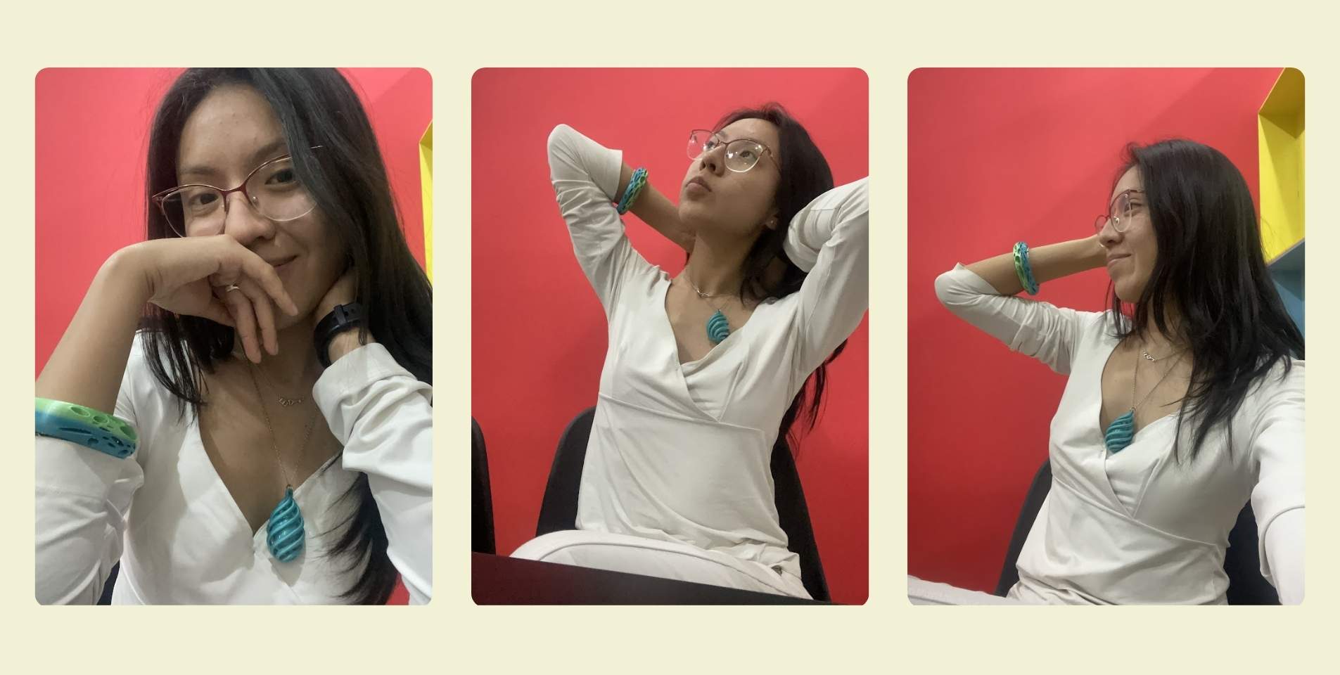
I'm not a model, but I wanted to share some photos of how the pieces look on, I think it was a great result!
LET'S DO A 3D SCAN!
3D scanning allows you to go from a physical object to a computer editable model in a matter of minutes, either through a cell phone camera, or a specific scanner for it.
Personally I used the photogrammetry technique, this is done by means of a cell phone and an application that you can download, it seems to me that all of them are paid, but taking into account the quality of the results and the tools they offer, the price is not bad.
Here is a list of applications that you can use to scan a 3D part:
- Qlone - Available for andriod and ios.
- KIRI Engine - Available for andriod and ios.
- Polycan - Recommended for very big things, but it also works very well with small objects.
- AR Code - For when the part has a lot of details.
- NeFR - More for virtual tours, but doesn't allow exporting for 3D printing.
- EinScan SE V2 - This is not really an application, but more of a scanner tool that has limited dimensions, although you also need to download their program to run the machine.
Aspects to keep in mind:
- It is photogrammetry scanning is very camera dependent.
- To take photos directly from the cell phone it is recommended to disable HDR and Live photo in case of iPhone.
- The lighting conditions must be good, it is better to do it with artificial lights because direct sunlight can dazzle a lot.
- Not only should you give information in one direction, you should also give information from above, below and rotate the object.
- You can scan monochromatic and matte objects, when they are shiny it does not work very well because of the reflectivity.
- You can use Autodesk-Meshmixer to fill gaps.
What applications did I try?
For this week I did scanner tests with two objects and in two different applications, Polycan and KIRI Engine, both are applications that you can download for Android and iOS, both are paid programs, but you can take advantage of the trial days they give you. But beware! Once you install it and log in, these trial days are expended, and in the future unless you log in with a different email, you will not be able to export what you have scanned.
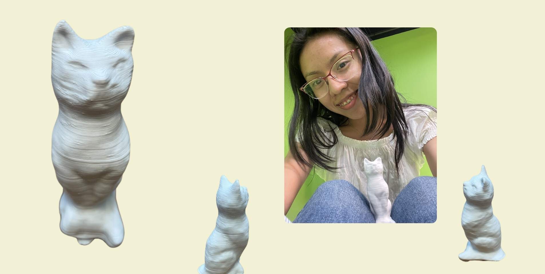
In Polycan I scanned a kitten and a sea shell with different backgrounds, and while doing it I always kept in mind to take twice as many photos as the minimum required to make sure I captured the details well. One good thing about this application is that it also lets you download files in different formats, such as obj, stl, among others. I leave you a little of the tests I did below, first I did it on a smooth surface and then on a surface with a checkerboard pattern, I really thought that the second one would come out better, however, the application is so great that it also scanned the background.
Finally, in KIRI Engine I scanned the same kitten again, but here I did not do the test with different surfaces, I did it only with the chess surface and it still came out in the scan.
Actually, what worried me when I did these tests was the reflectivity that the original kitten has due to the material it is made of, and in the case of the shell, its size and amount of details. But despite the chess-textured base, the scan came out better than I thought, with quite good quality, and I suppose I also owe something to the camera on my cell phone, I have a iPhone 12 and the camera continues to have excellent quality .
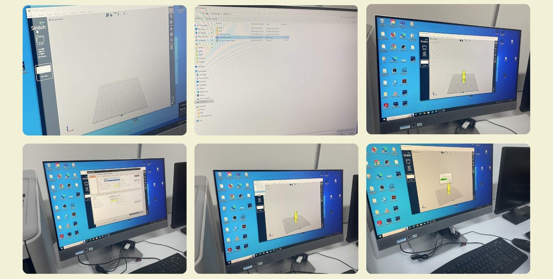
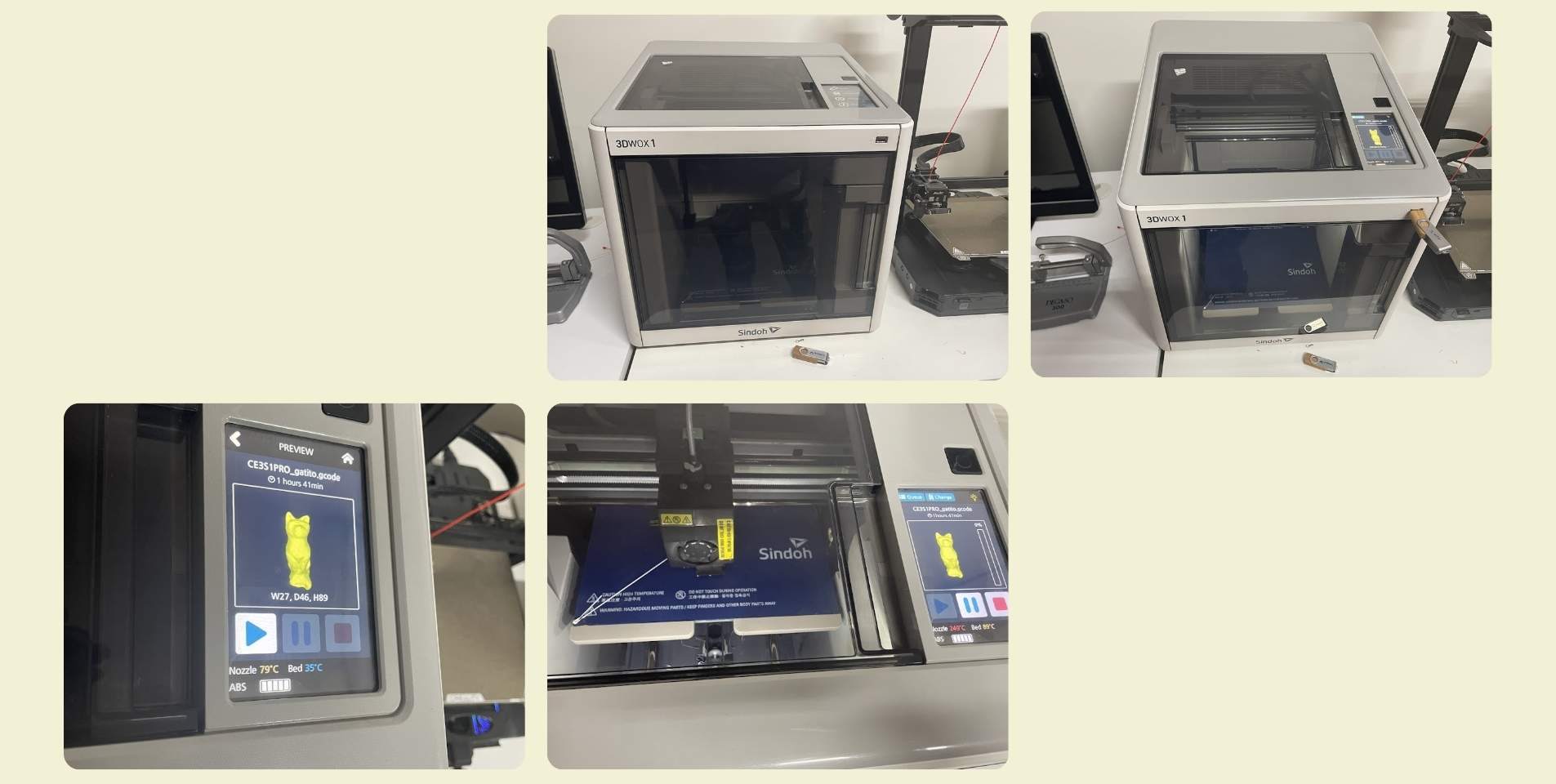
How did I print it?
To print the scan I made of the kitten on Polycan I used a Wox Sindoh 3DX printer. So I had to use this printer's program to configure printing, although I also received some help here, and surely the parameters were the recommended ones that were already there. After 2 hours and 9 minutes the print was done. It had an issue on the base, and I think I was really lucky that the whole piece came out, because it looks like the base came off a little bit, but it could also have been because of how they took it off the print bed. In either case, I think it could have been solved with a support on the base, or by trimming the scan a little, since after I realized that the base of the scan is not flat, so surely that had an influence as well.
Conclusion
Learning how to set up a part for printing takes time, and also testing. After a day and a half of pure printing tests I was already able to make the recommendations. I find it to be an excellent tool, one of the best for rapid prototyping. Before there was printing, but I had never had to do the configuration by myself, I had to play and experiment with the tools to understand how to correctly send a piece for printing... One of the learnings that this left me was that until you do the things by yourself, you don't learn how it's really done.
On the other hand, I really enjoyed experimenting with the application scanner, sometimes I can't believe that technology has evolved so much, and it gives me a certain nostalgia to think about my past with technology limited to today, where in a few weeks in my final project I may be part of this evolution... It's a little more scary than exciting, but fear or not, I see them there.
Files
- Pendant ___ STL
- Pendant ___ Rhinoceros
- Bracelet ___ STL
- Bracelet ___ Rhinoceros