WEEK 3
COMPUTER CONTROLLED CUTTING
This week's challenge was to make a practice of power and speed of a laser cutting machine in a team, in addition to personally develop a set of construction parts in laser cutting, which could be parametric, so that, when editing a measure, by means of equations the whole piece changes as a whole and thus reduce the working time. A vinyl cutting practice should also be attached to this deliverable.
COMPUTER CONTROLLED CUTTING
The first practice was given together with the other members of FabLab Puebla. During this practice we were able to learn a little about how a laser cutting machine should be calibrated, this so that in the individual practice we could have clean cuts and accurate dimensions.
- Leave a distance of 5mm from the nozzle end of the machine to achieve a better focal point against the surface of the material.
- Avoid cutting materials that may melt or catch fire easily or whose high temperature cutting may release toxic vapors.
- Consider characterizing the laser at 40mm/s speed and 50% power to obtain a clean cut.
- Kerf is what burns in laser cutting, if not taken into account you can have parts with a smaller size than you expected.
- To get the Kerf you divide the distance by the number of cuts.
- Consider "material - Kerf" to get a clean notch that will fit properly.
- Live hinges can be made in a rigid material to provide movement. For that you need to perform a very easy equation (sarcasm, you are almost not intimidated by this equation) that you can find in the FabLab Puebla link below.
To see the complete practice I invite you to visit the following link where everything is more detailed.
On the other hand, we had an introduction to SmartCarve by the instructor Albero Blanco at FabLabPuebla.
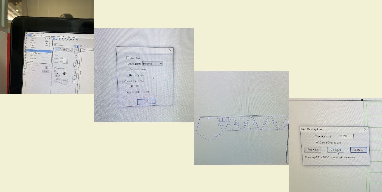
SMARTCARVE is a program that works with layers and opens files in DXF format, it has no pixels so it works with defined lines. This is the program that the laser cutting machine works with.
Things I learned:
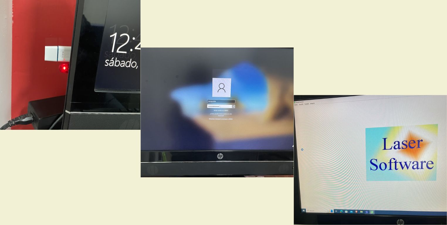
- A special key in red USB format is required.
- Allows to open several files in a single document for cutting.
- Allows easy replication of parts.
- It has specific layers for cutting and engraving. The blue color will always be for cutting.
- There are 5 layers that cannot be modified (10 -15) are default for engraving.
- You can modify the parameters of the layers.
- Be careful with double lines, but the program still allows you to remove them.
- The cutting order to be followed is as follows
- Engraving
- Internal cut
- External cut
LASER CUTTING CONSULTANCY
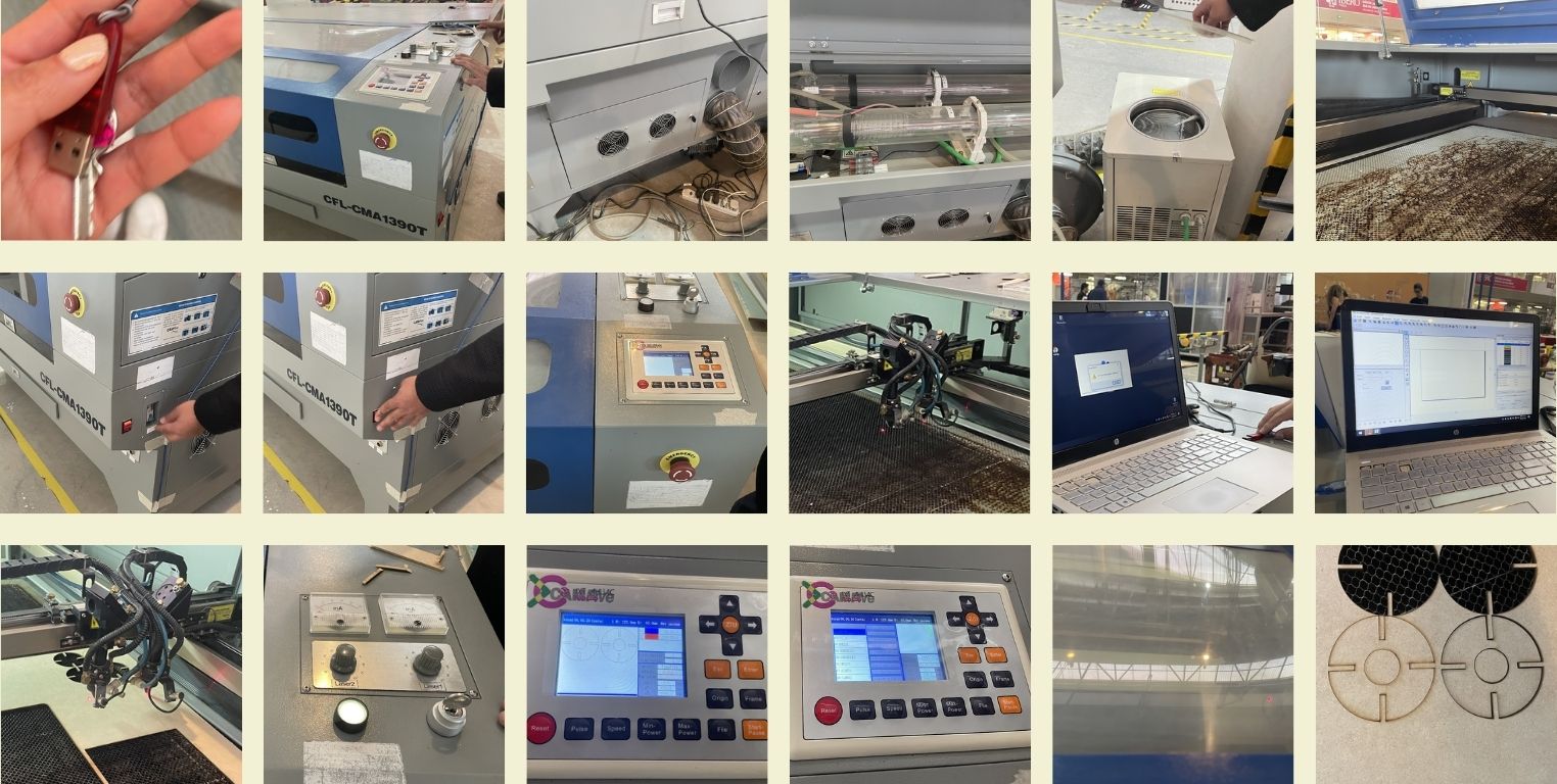
We were also given personalized consultancy to each of us during this week to learn how the laser cutting machine works and how to use it. Below are some photos that I took during my consultation with Carlos, a member of the FabLab Puebla team.
Aspects to keep in mind
- A special USB key is needed to use the SmartCarve program for the laser cutting machine in addition to the machine key.
For start-up:
- Verify that the ventilation is clear and turn on the machine.
- Turn on the machine and remove the safety button.
- Insert the key into the machine.
- Turn on laser.
- Turn the power to maximum.
- For safety reasons, always close the machine while it is cutting.
- To turn off the machine, follow the same steps as when turning it on, but in reverse sequence.
- To start cutting, click on "Start" inside the program.
LET'S MAKE A PARAMETRIC DESIGN!
For my individual assignment I used Fusion 360, a CAD Software that is cloud-based for product design and manufacturing with parametric 3D modeling tools, allowing to save time when designing different parts.
In a sort of challenge, I wanted to learn how to use the program. I started with the design of the building pieces, and the truth I could only think of my nephew using the pieces to create something. So I wanted to develop geometric figures that would allow him to build different polyhedrons, and on the other hand learn about it.
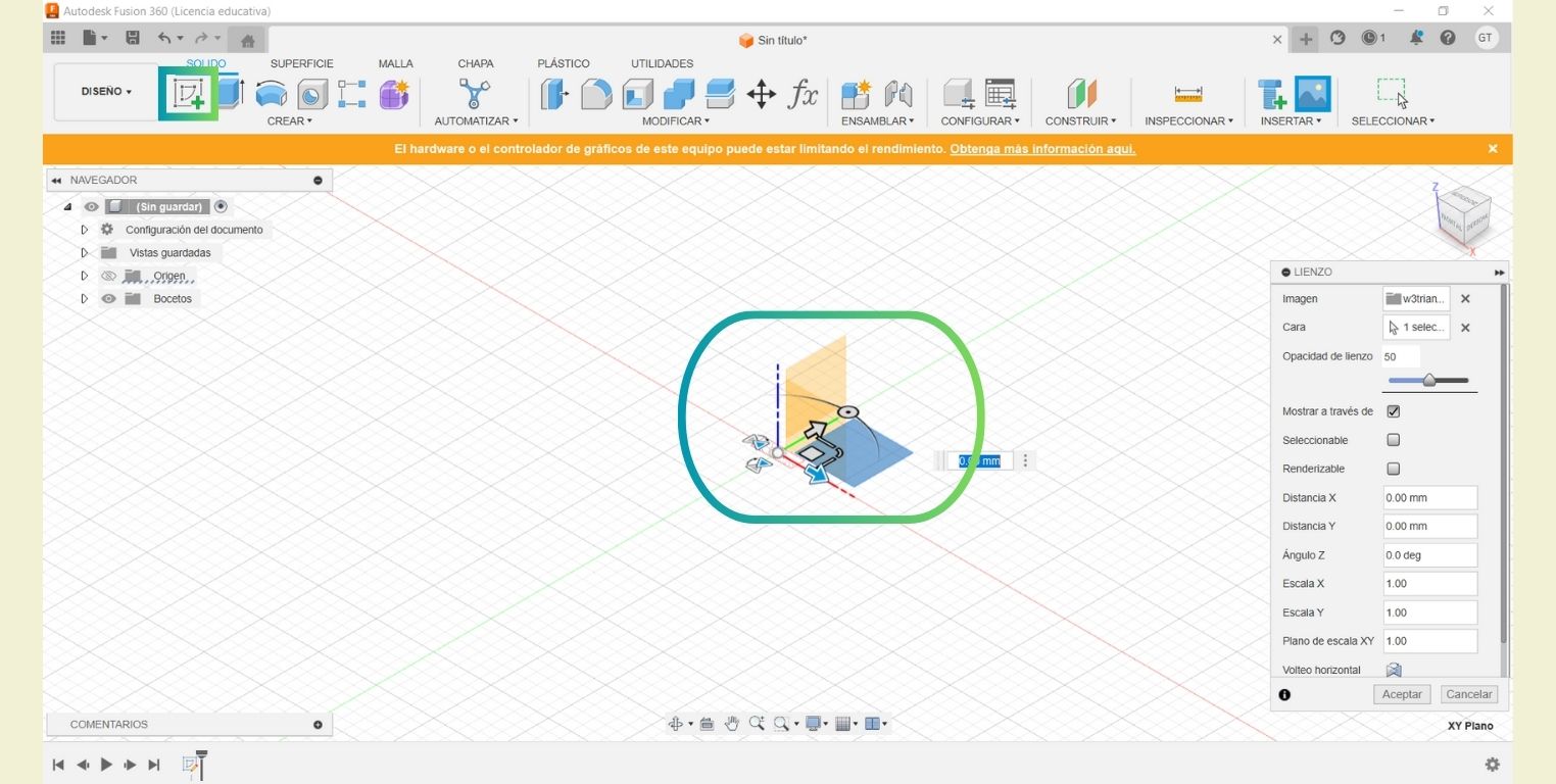
In a new file I chose a plane to make a first sketch.
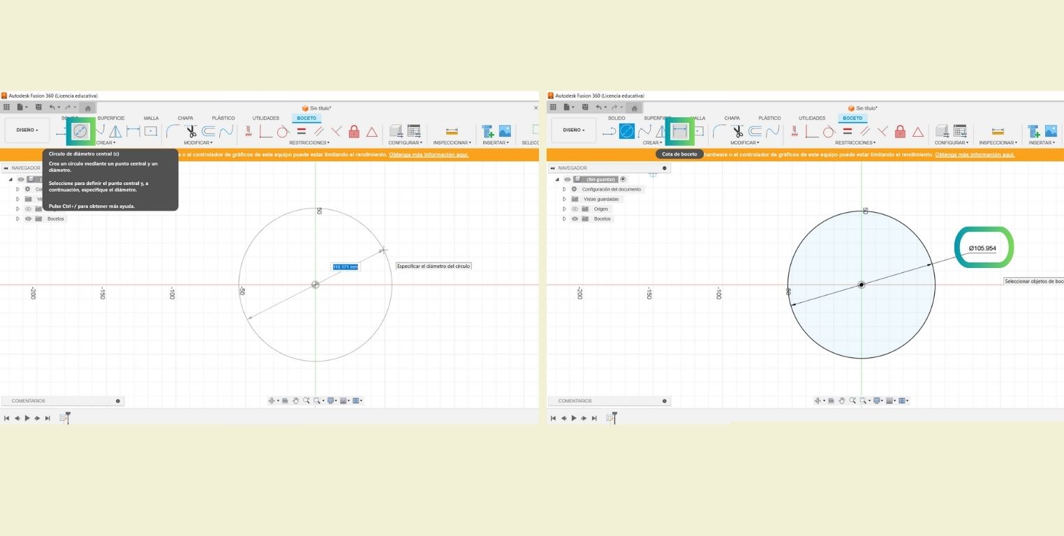
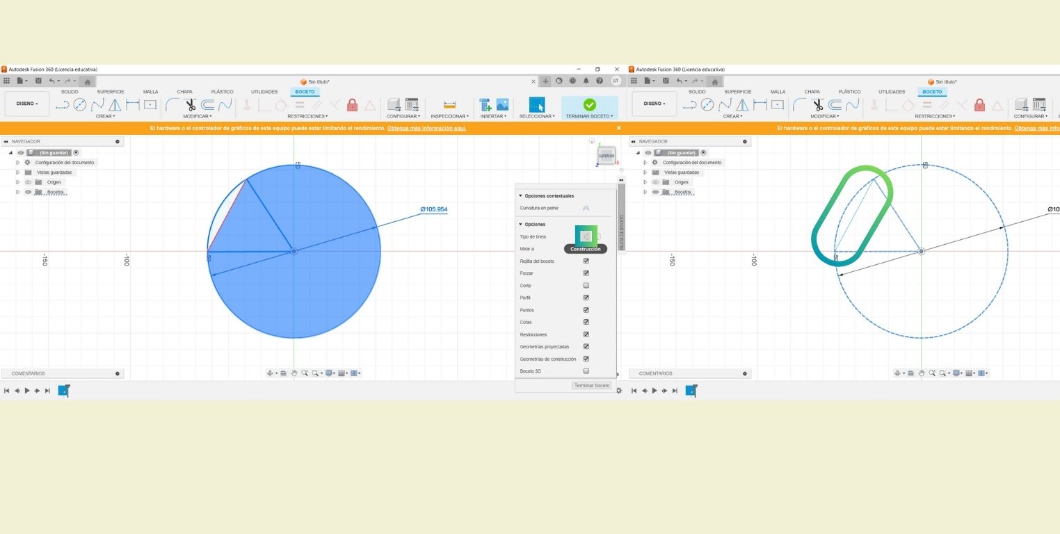
I drew a circle starting in the center without a specific measure, then with the "Sketch dimension" tool I drew the dimension of my circle.
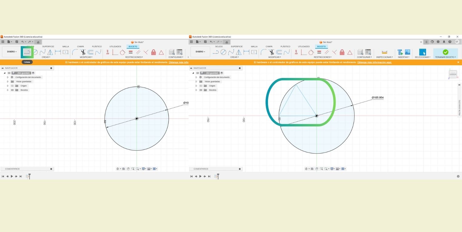
Then I drew over it a triangle with the "Line" tool.
The next thing was to select all the stroke, except the line that would draw an arc on the circumference to put them as "Construction" lines and become dotted.
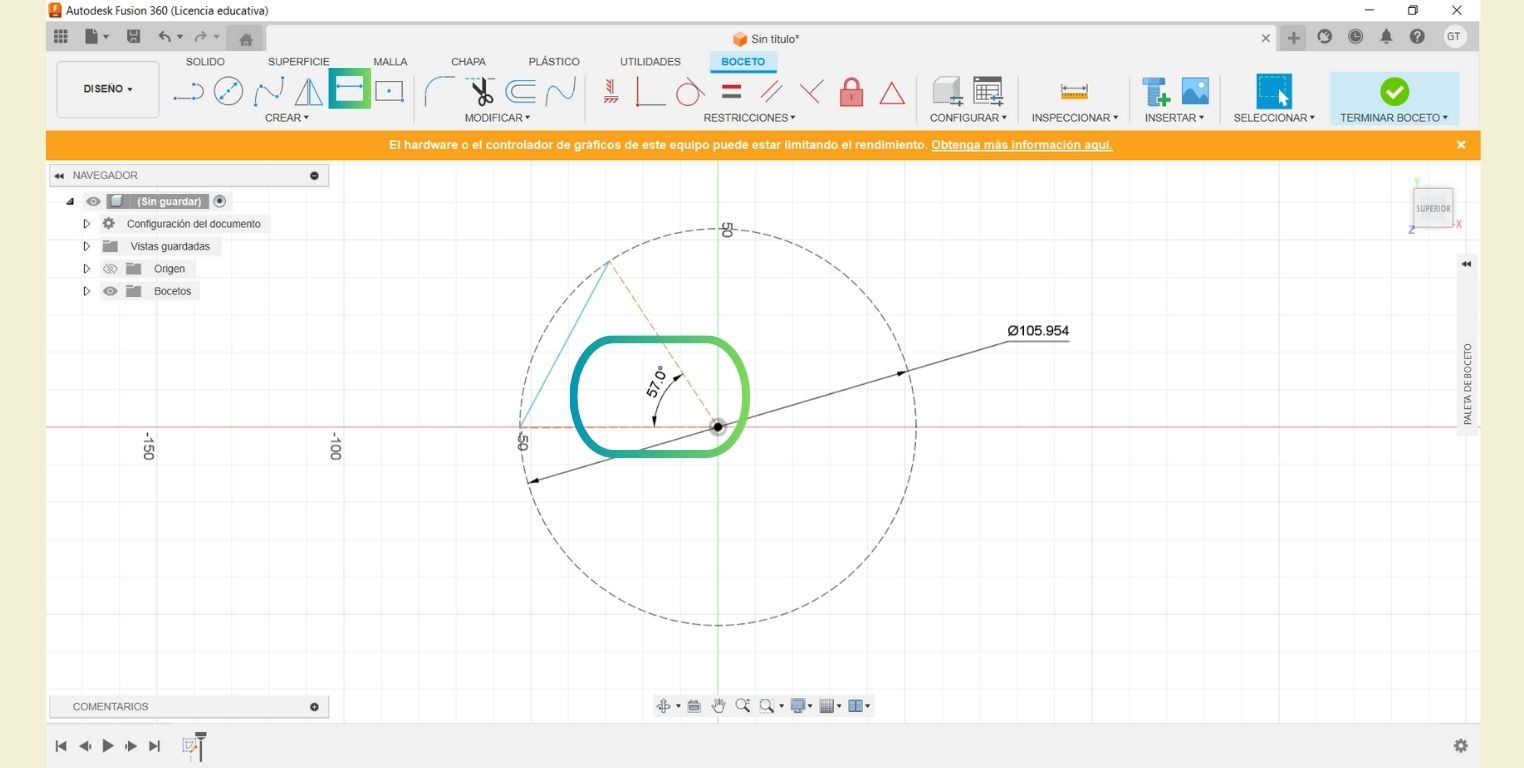
Before finishing this first sketch I drew the angle of the triangle with the help of the "Sketch dimension" tool.
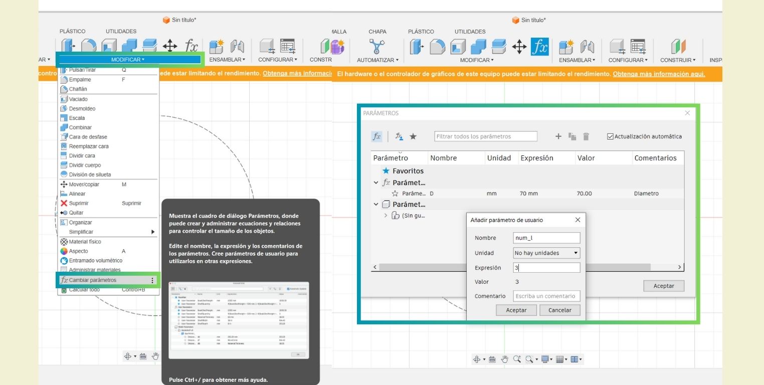
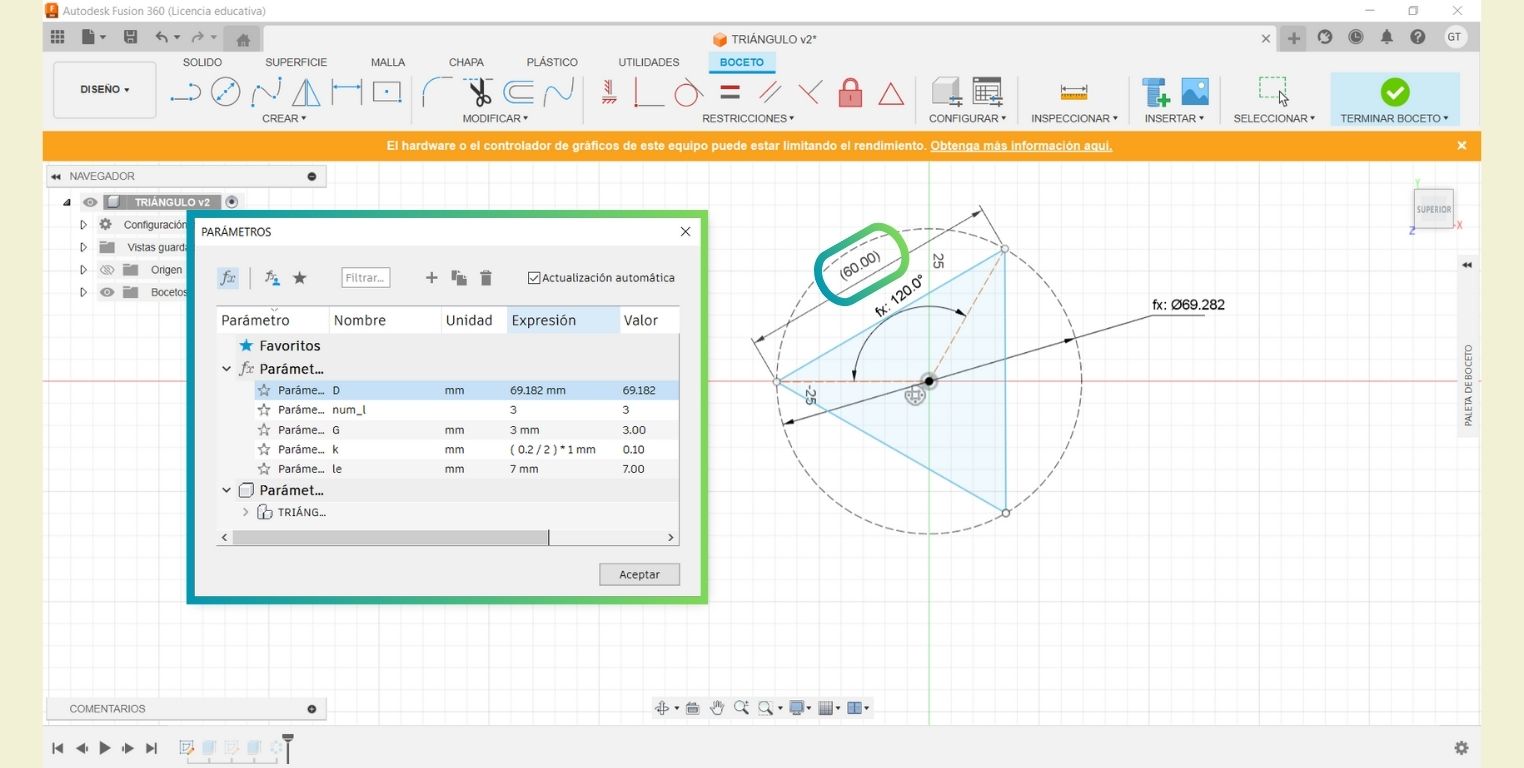
In the "Modify" menu I opened the "Change parameters" tab. There I added 2 first parameters, the first one was the diameter in mm that I represented with "D" and the second one was the number of sides that I represented with "num_l". This is because the above was the basis for making different geometric figures, starting with a 3-sided triangle.
In the bottom part where the history appears I right clicked to be able to "Edit sketch", and then change the dimensions by the parameters that I added. In the circle I put the value of the diameter represented in the equations as "D", and in the angle I indicated that it would be 360° divide in the number of sides "360/num_l".
Selecting the only continuous line in the "Create" menu I selected a "Circular pattern", which, when I selected the center, automatically generated 3 lines, however, to make it parametric I changed this value by the number of sides, represented in the equations as "num_l".
I finished the sketch and added 3 more parameters. The first one was "G" to insert the thickness of the material. The second was "k" to represent the kerf, and finally "le" to indicate the length or depth of the extrusions I will make for the assemblies.
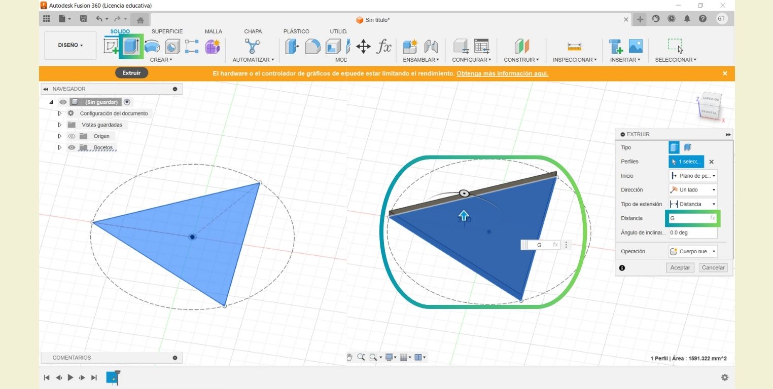
I selected the surface of the triangle and extruded it with the "Extrude" tool, and in the distance instead of putting a number, I assigned the parameter "G" to give it the thickness of the material to be cut.
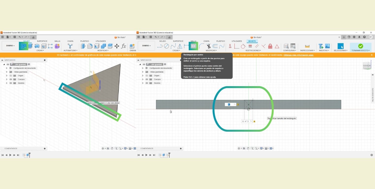
I made a new sketch in one of the lateral faces of the triangle and there I drew a "Rectangle by center" and positioned it in the center of the triangle face. Then I took the opportunity to add the parameters, lengthwise "G" and widthwise "G-K*2", the latter because as we saw in the group practice when making an indentation for assembly this is better if you take into account the thickness of the material minus the kerf, which in this case as in the equation was divided into 2, it was necessary to multiply.
I finished the sketch and selected the rectangle I drew before extruding it. Then in distance I added the extrusion length parameter "le" in negative to indicate the direction and in operation I chose the option "cut".
Then I made a "Circular pattern" of the cut faces with respect to the Y axis represented in blue, and in quantity I put the parameter of the number of sides "num_l".
From this piece I plan to make other figures, all with the same length of each side. So I went back to edit the original sketch and took a reference dimension from the line where everything started, then I changed the diameter value in the equations until the dimension showed me that it already measured 60mm.
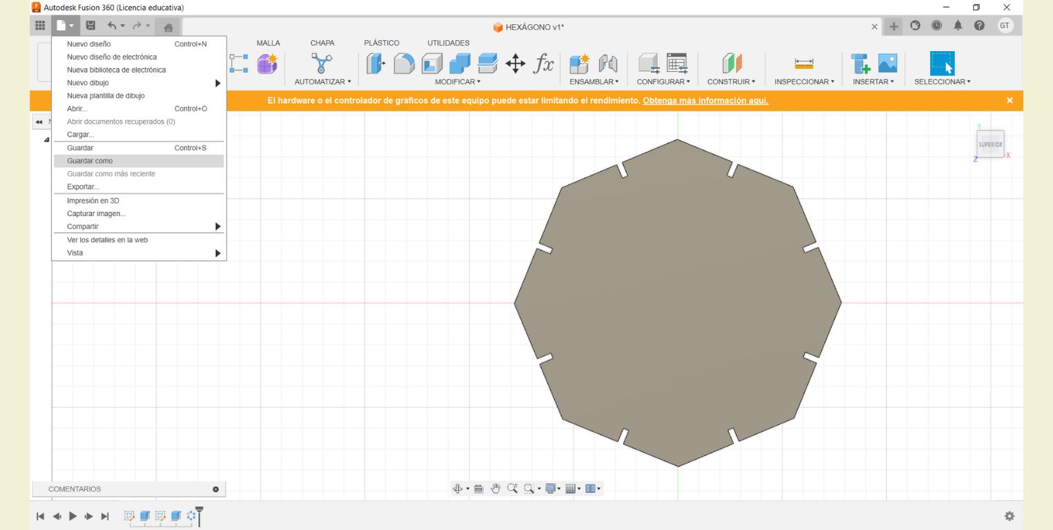
The next thing was to save the part and then I could export it in DXF. Something to keep in mind is that, if you don't save first, the Fusion 360 program won't let you export the drawing.
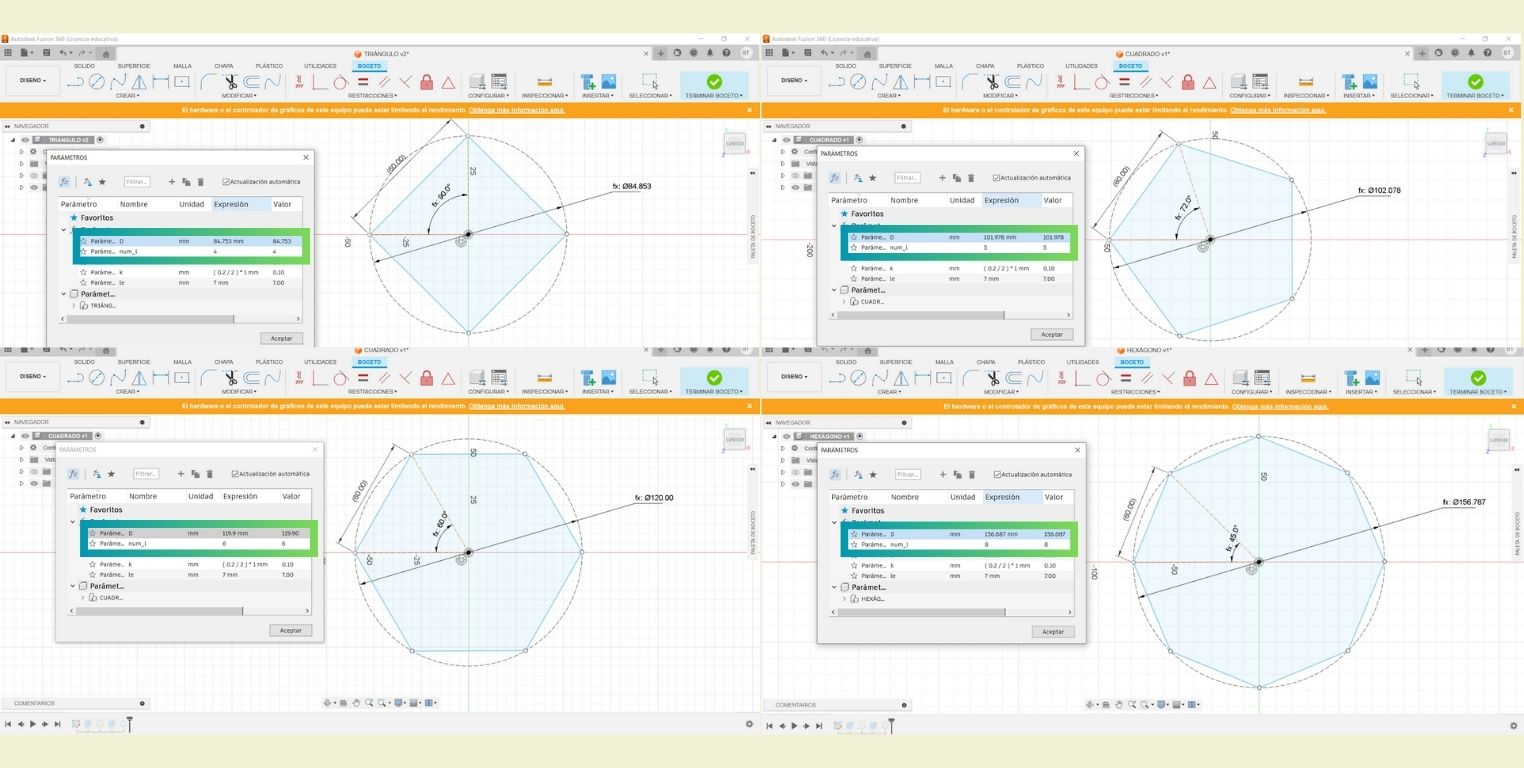
Once the triangle was saved, I modified the same file to make the following figures. The only thing I changed for each of the figures was in the parameters part the number of sides and the value of the diameter so that all of them had a side length of 60mm.
Between each modification I saved the new figure and exported it. For this, instead of saving as normal, I chose the option "Save as" to create a new copy and have the files separately.
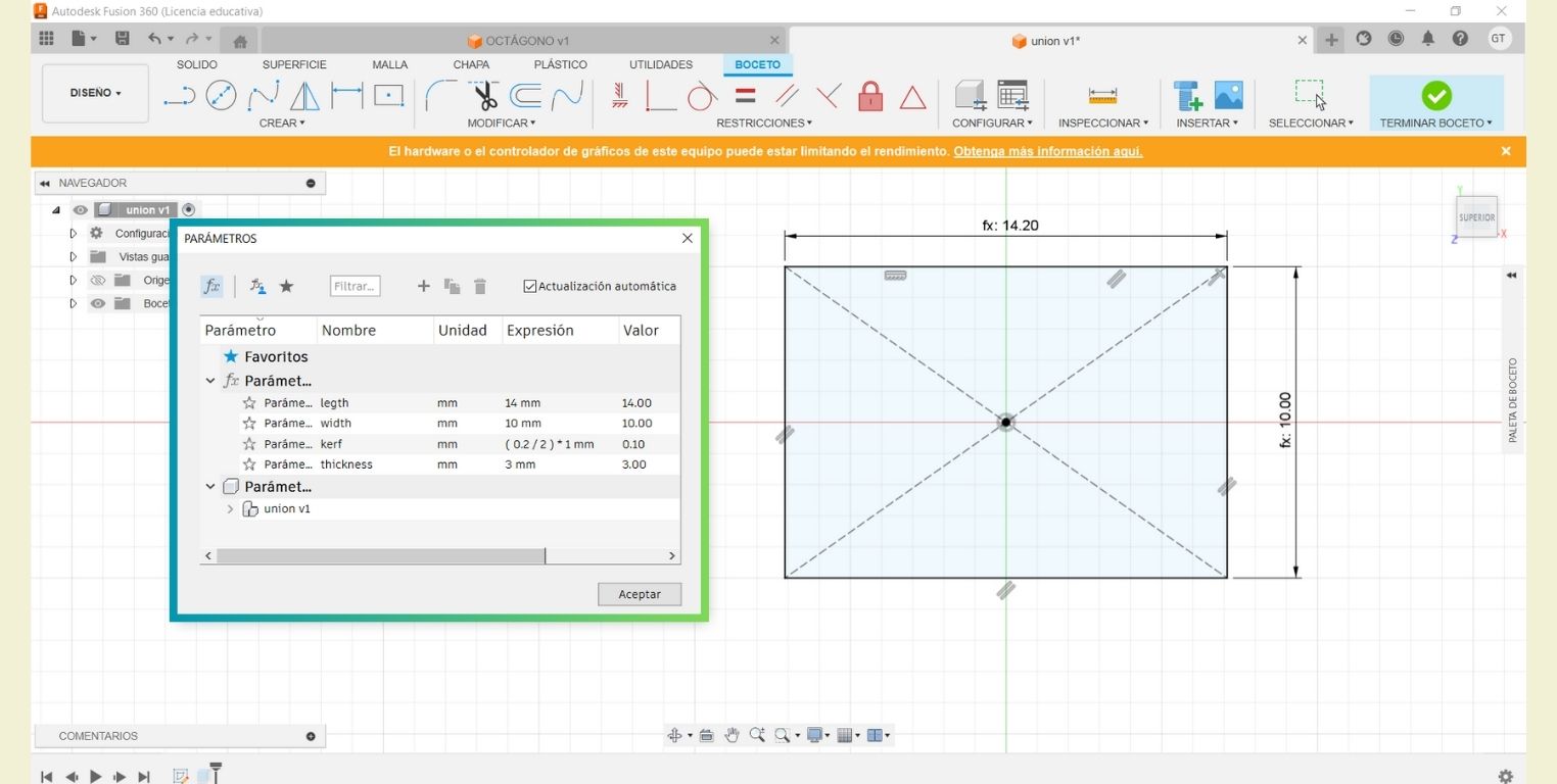
Finally, for the union I made a rectangle and parameterized it with the following values.


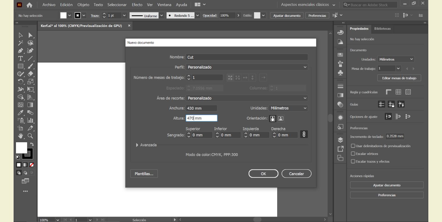
Running the files through Illustrator!
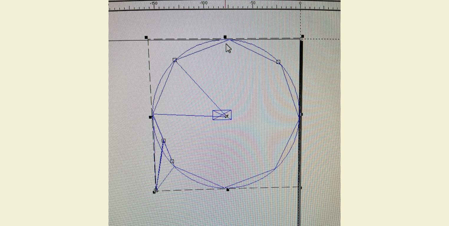
The first time I tried to make a laser cut with my DXG document imported from Fusion 360, my file looked very strange, actually I think it was the mix of the sketches and the extrusions I had made, however, it did change a lot of things. So I opened it in Illustrator to verify that my file was not wrong (Below I attach evidence of how it opened before).
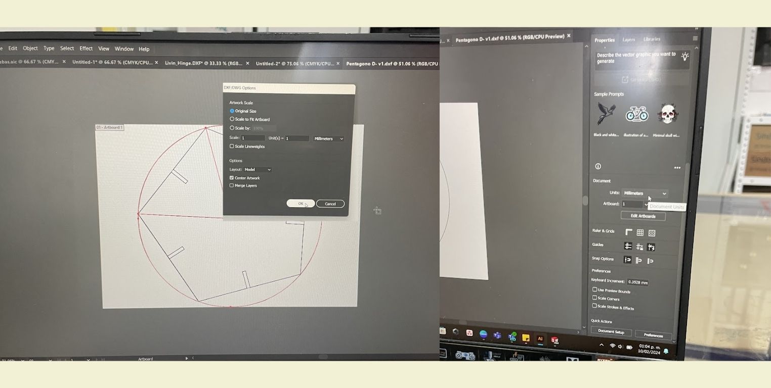
- In Illustrator I opened my file in the original size and verified the dimension, because it gave me the perception that it was too small, and indeed it was, but fortunately I only had to change the position of the decimal point to make it exact.
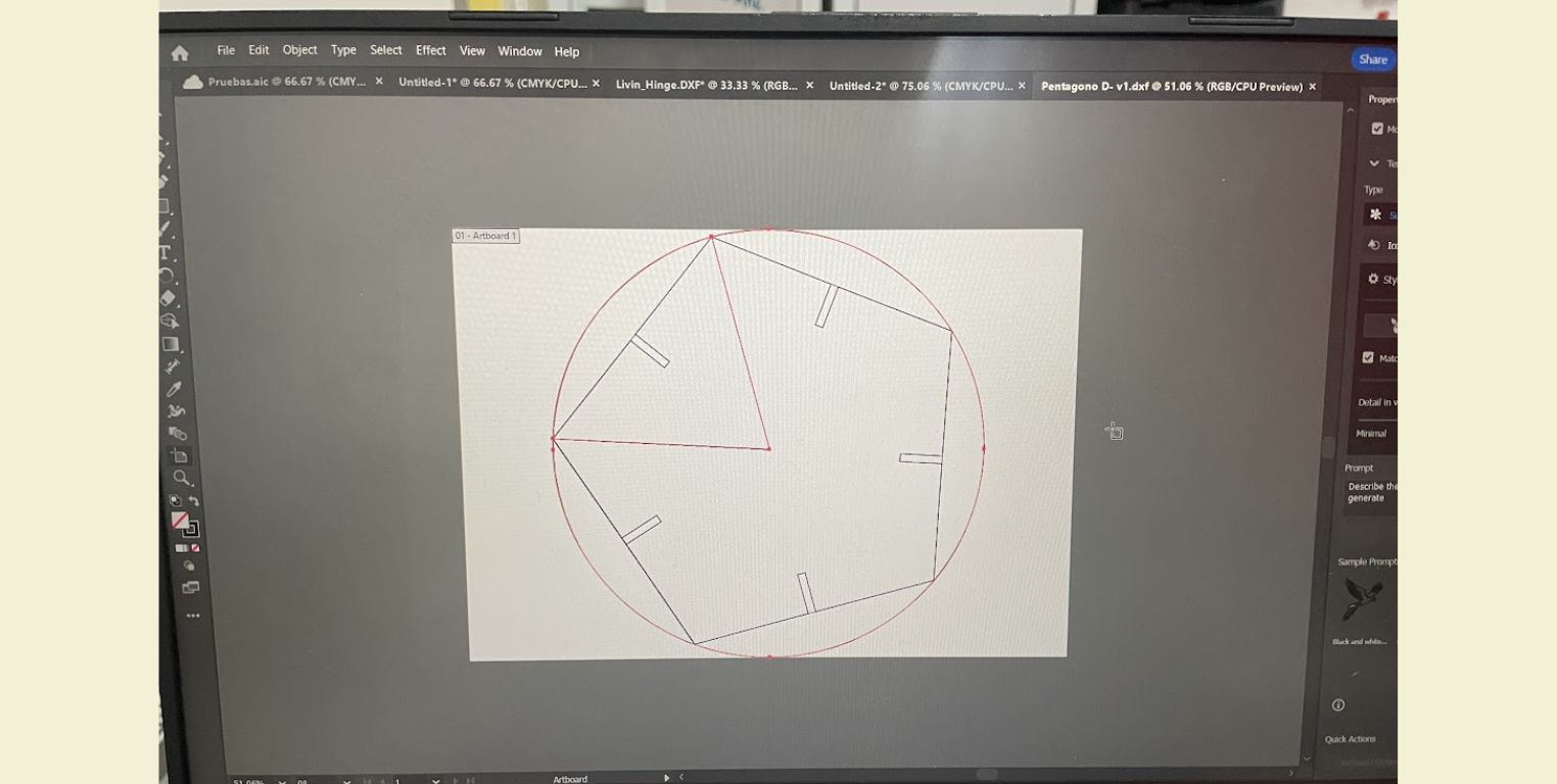
- I also took the opportunity to eliminate the lines of the sketches that I did not need, such as the circumference and the line from which all the figures started.
I repeated these steps with each of the files of my pieces and I exported them separately to DXF, and in this case Illustrator let me choose the year of the version. In the case of the IDIT machines, it is recommended to work with the year 2000 version.
You can find these files in the file section below.
LET'S LASER CUT WITH SMARTCARVE!
- When I cut a person before me had left the machine on, so the first thing I did was to insert the program key.
- I logged in with the university account.
- I opened the SmartCarve program
- From the program I imported my 2000 version DXF file.
- I arranged it and verified that it did not have double lines so that the laser would not pass through the same place twice.
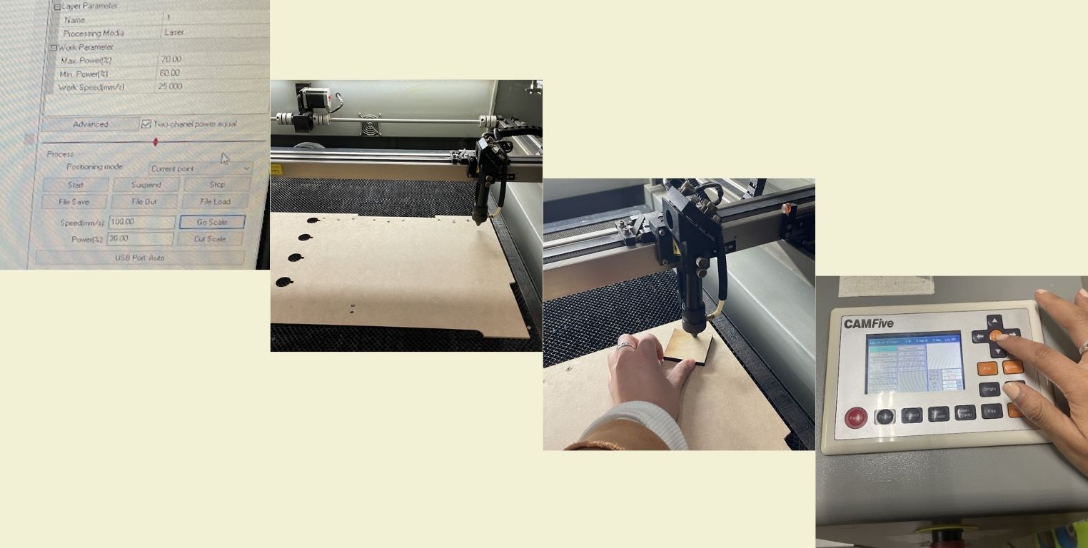
- I set the respective values
- Max Power(%) 70
- Min Power(%) 60
- Work Speed(mm/2) 25 000
- Speed(mm/s) 100
- Power(%) 30
- I positioned my material on the machine screen and with the help of the buttons on the machine I calibrated it so that it was 5mm above my material. To be sure I positioned it correctly, I checked the cutting space by clicking on "Go scale".
- When it was all set I closed the machine, turned on the laser, gave it full power and in the program clicked "Start".
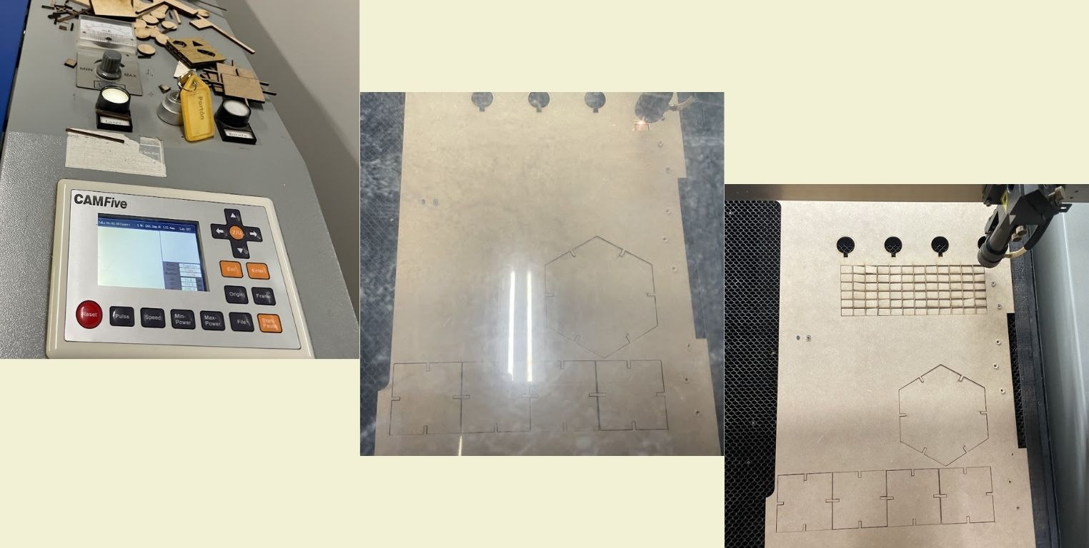
With this practice I realized that this step can be as fast or as long as you want it to take. The ideal is to have all the pieces you are going to cut in a single file, because although the SmartCarve program allows you to open different files and arrange them at the moment, it does not do it in a way that the waste of material is less and it still takes a little time to position everything. In my case, I recycled 3mm MDF that I found in the "Wood" area in IDIT where everyone puts the wood material that they are no longer going to use, and to tell the truth, most of the time we can find very good material to work with.
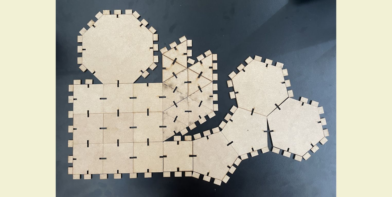
Let's build figures with the construction pieces!
The complete kit of geometric figures for construction that I cut is composed of:
- 10 triangles
- 10 squares
- 2 pentagons
- 2 hexagons
- 1 octagon
- unions (many)
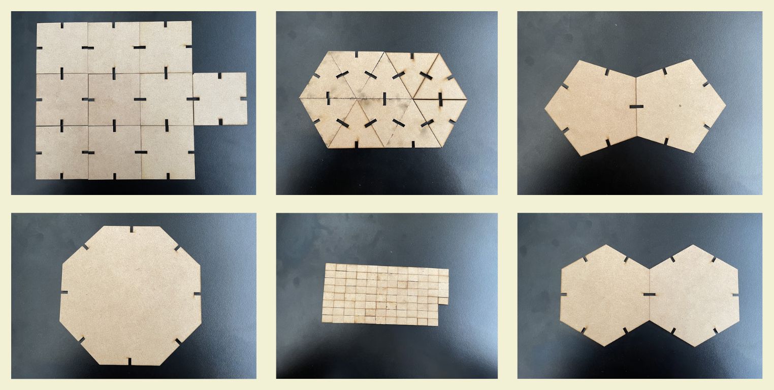
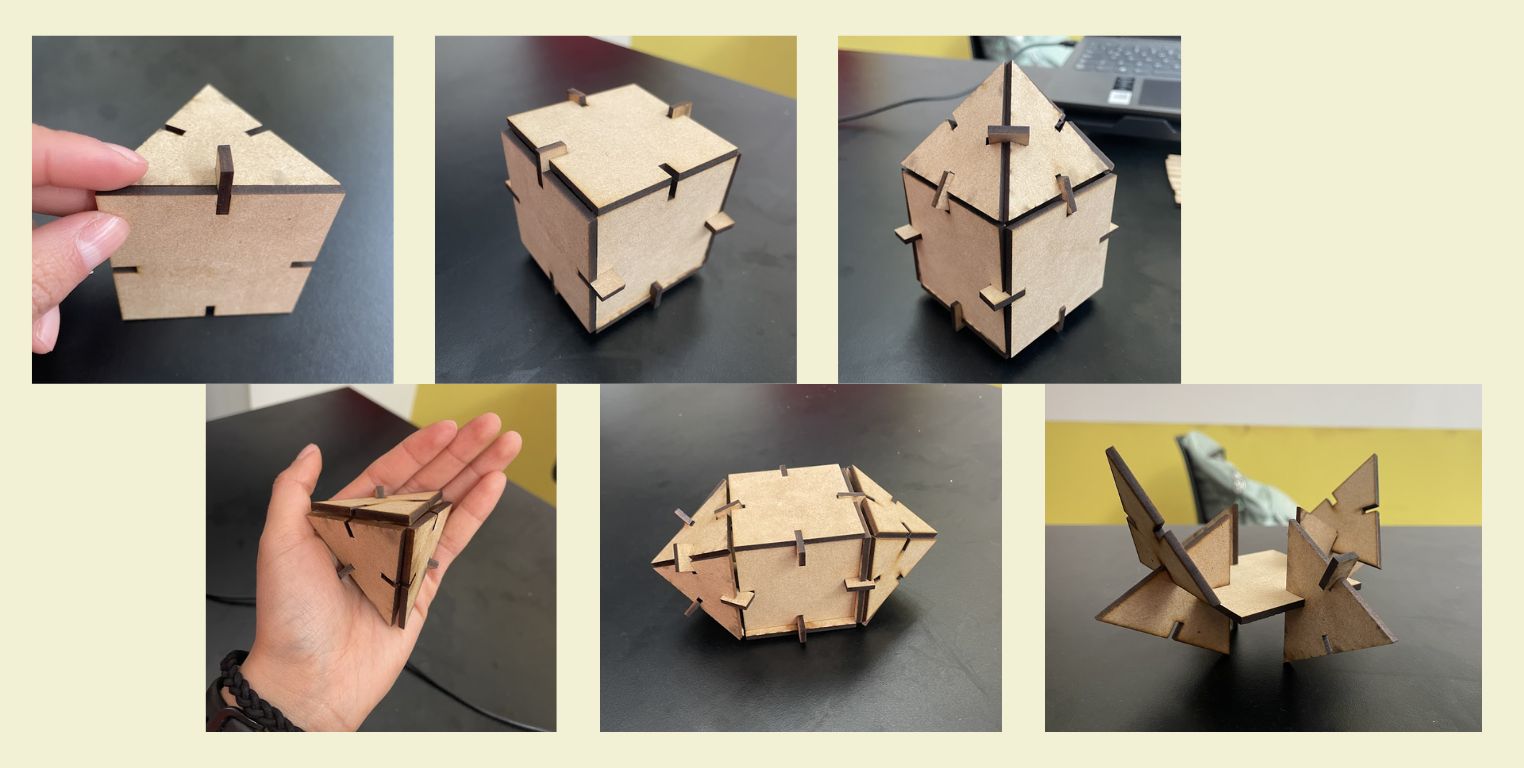
The easiest thing would have been to cut 10 pieces of each figure, however, the challenge is also that you can make different polyhedra with what you have, and it seemed to me that the easiest figures to manipulate could be the smallest ones, so there are more of those.
Below, I share with you pictures of some of the polyhedra I built for evidence of how they work. Soon I hope to be able to see my nephew and enjoy this building game with him too.
LET'S MAKE A DESIGN FOR VINYL CUTTING!
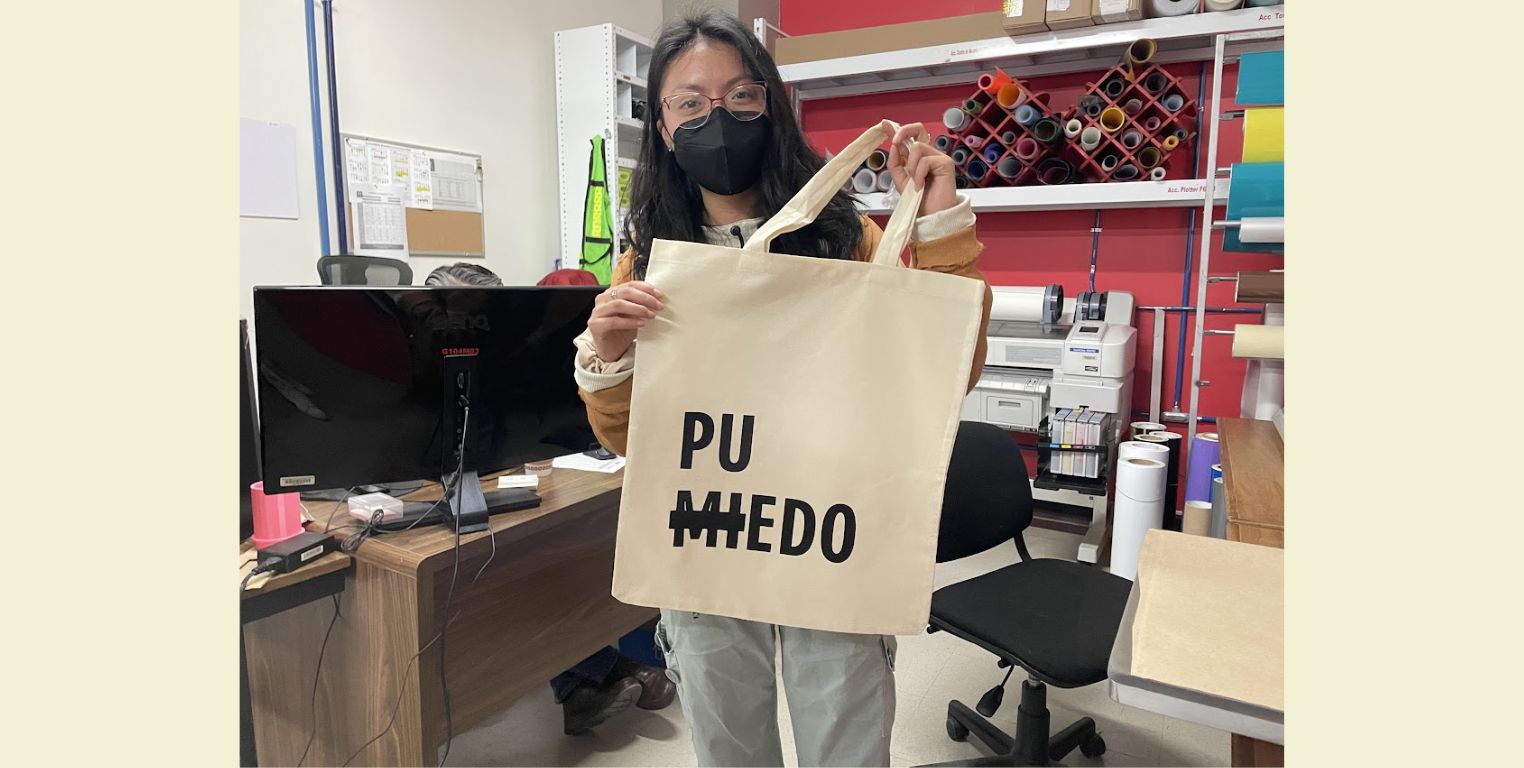
I've always been a fan of phrases, so I wanted to cut one out of textile vinyl and then attach it to a bag, since I'm always carrying one around because my backpack is not enough space for everything I carry.
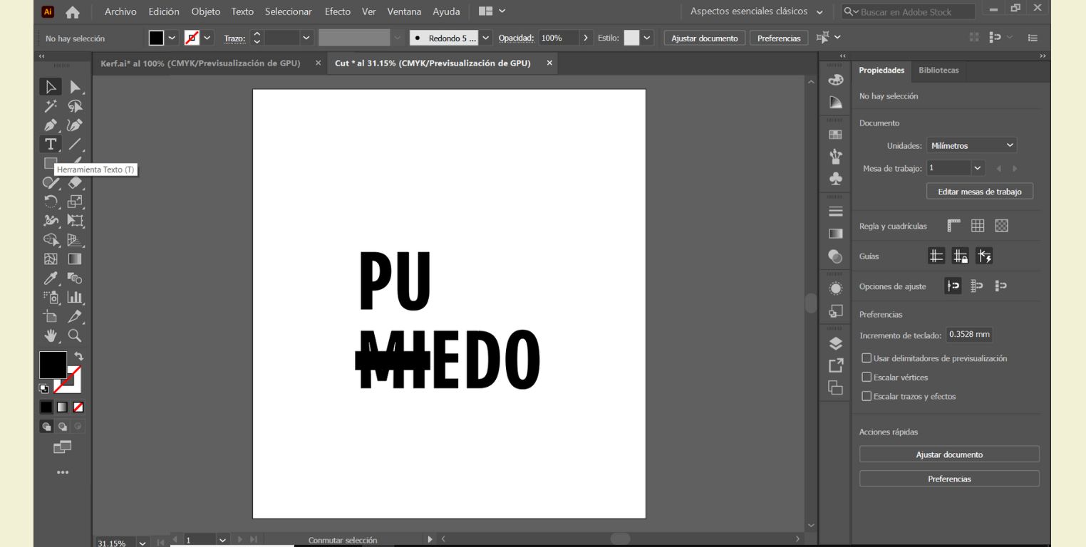
- In a new Illustrator file I made a worktable with the dimensions of the area of the bag where I wanted to put the vinyl.
- With the "Text" tool I wrote the syllable "PU" and the word "MIEDO" (fear in English), and then remove the first letters of the word and put the syllable, then a play on words is created in Spanish and instead of "fear", you can read "can". I really liked the idea of conveying that, despite the fear, I can go ahead with what I have planned.
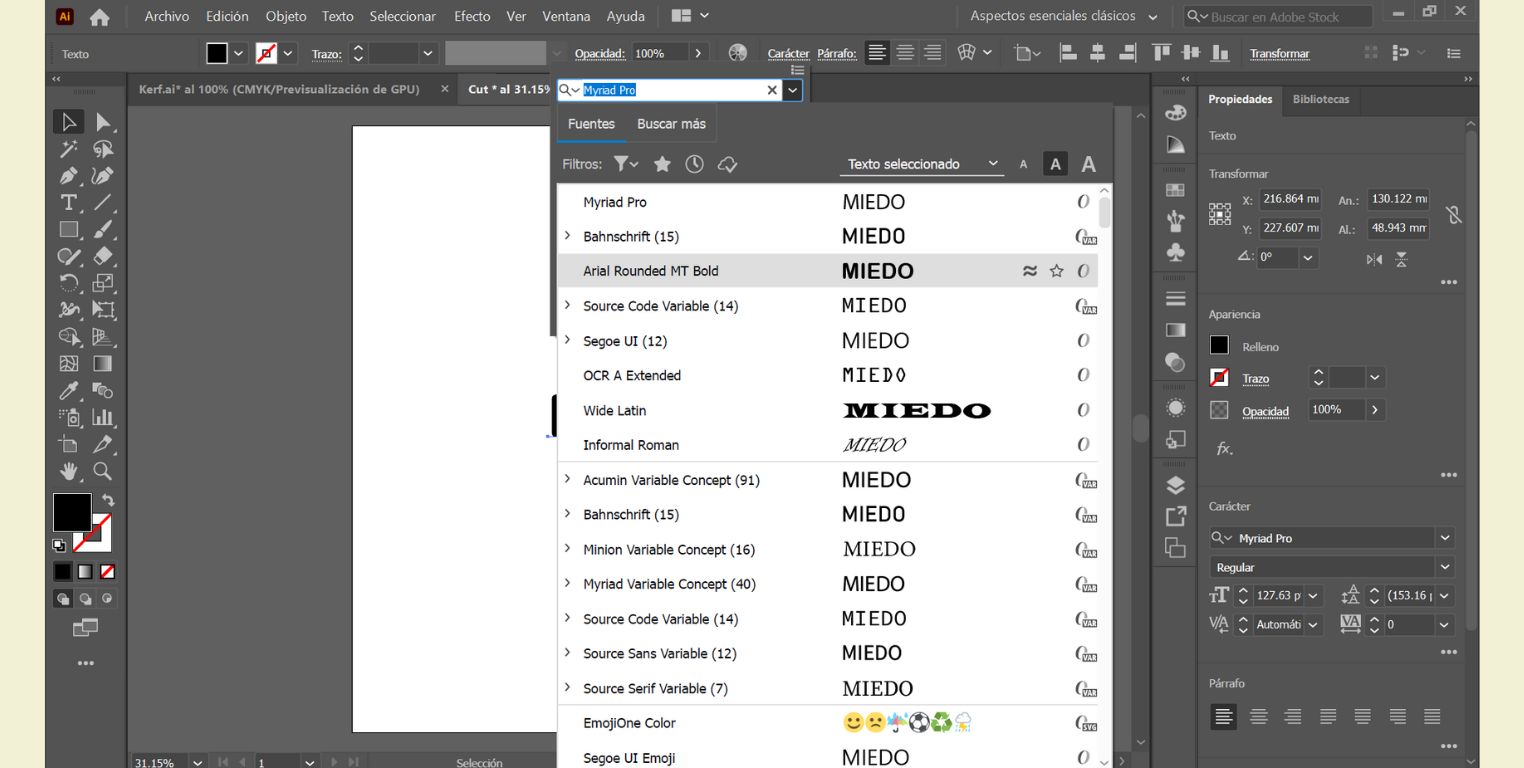
- Then in the "Character" part I chose a typeface that I liked.
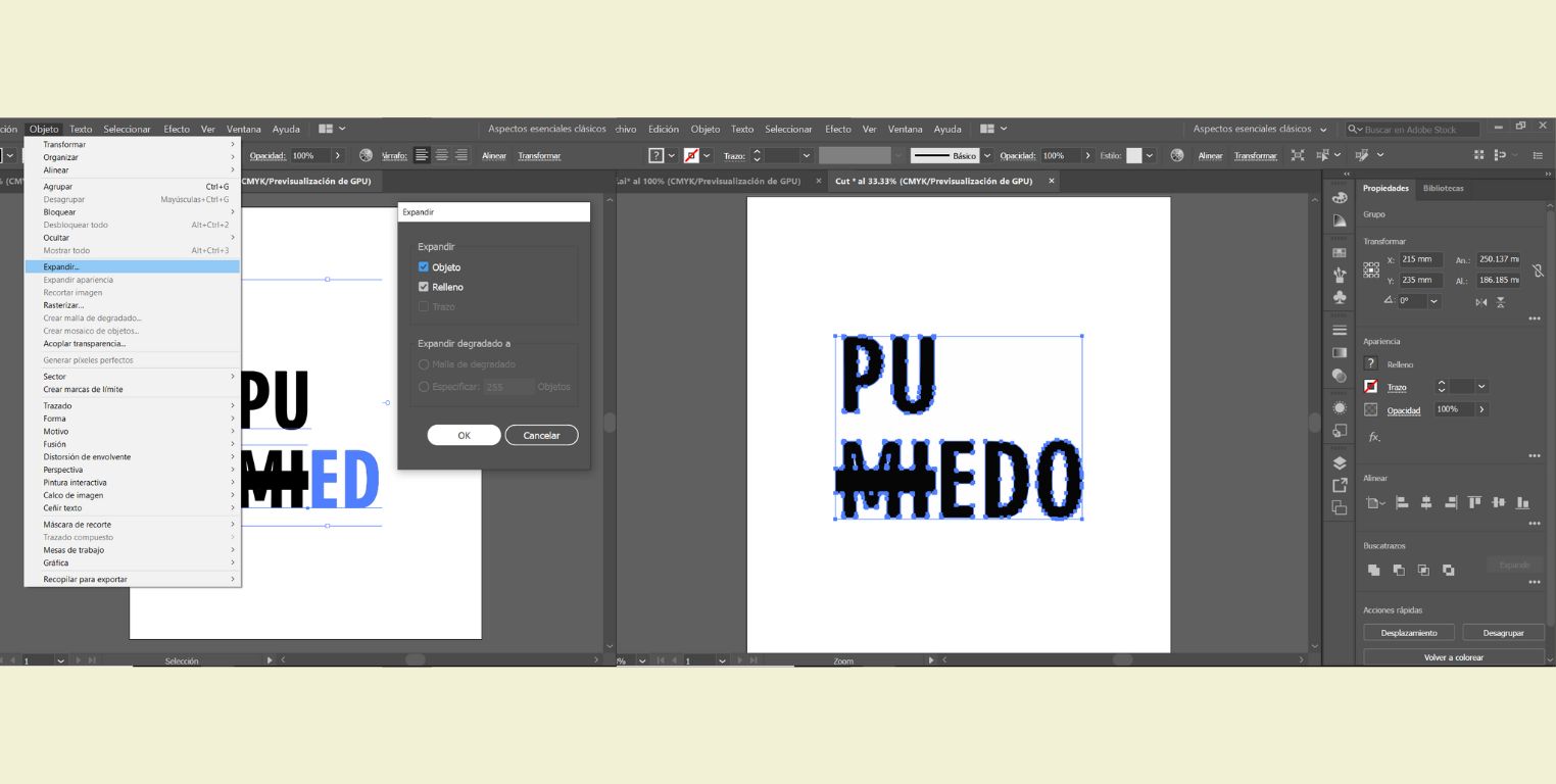
- The last thing was to convert my text to vectors, for that I selected my text and in "Object" I clicked on "Expand". To verify that it was done, I ungrouped everything and indeed it was already in vectors.
- Then I saved the document as "EPS" in version 8.
Cutting textile vinyl
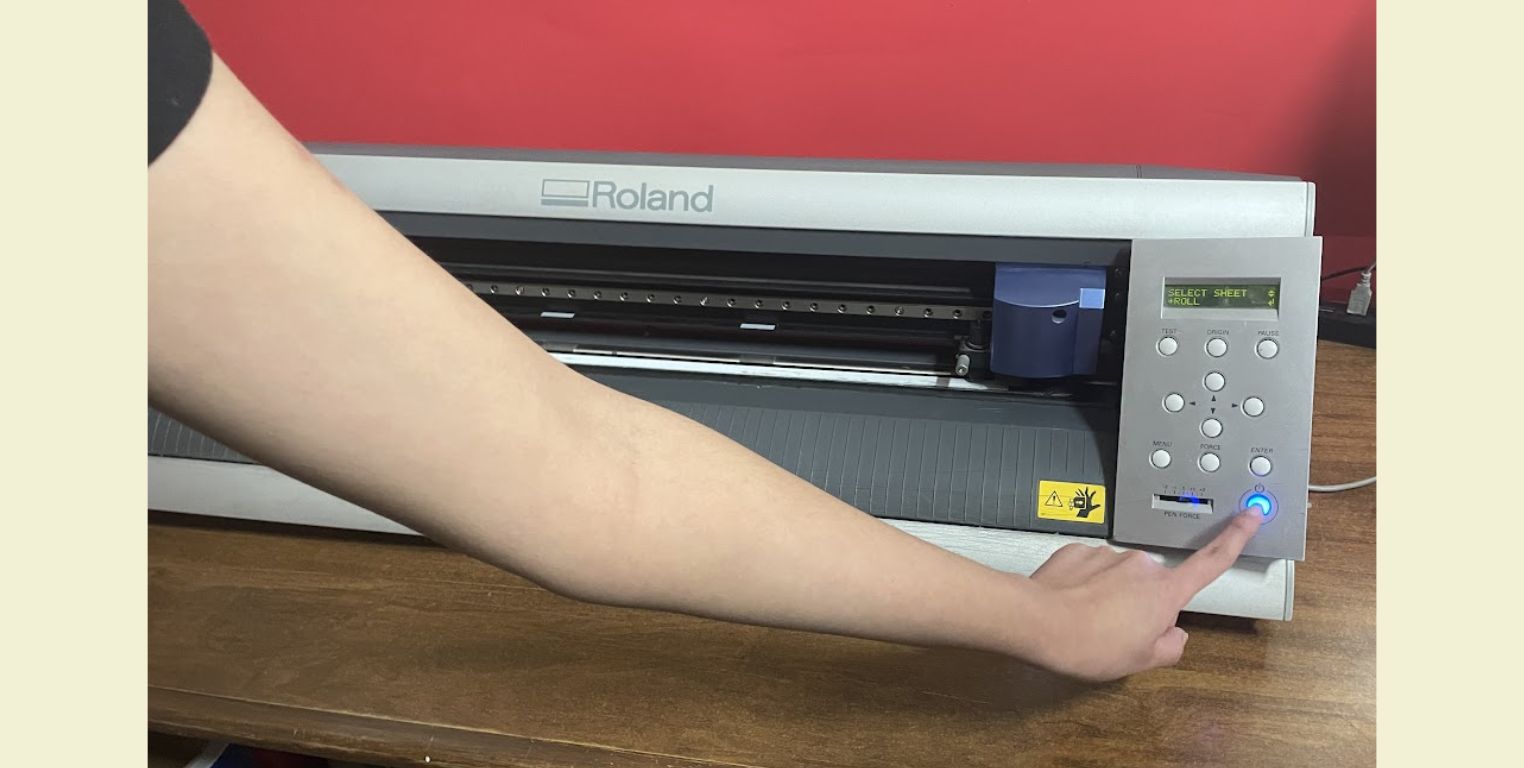
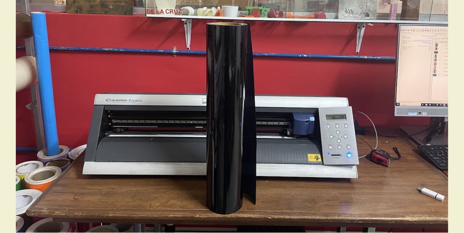
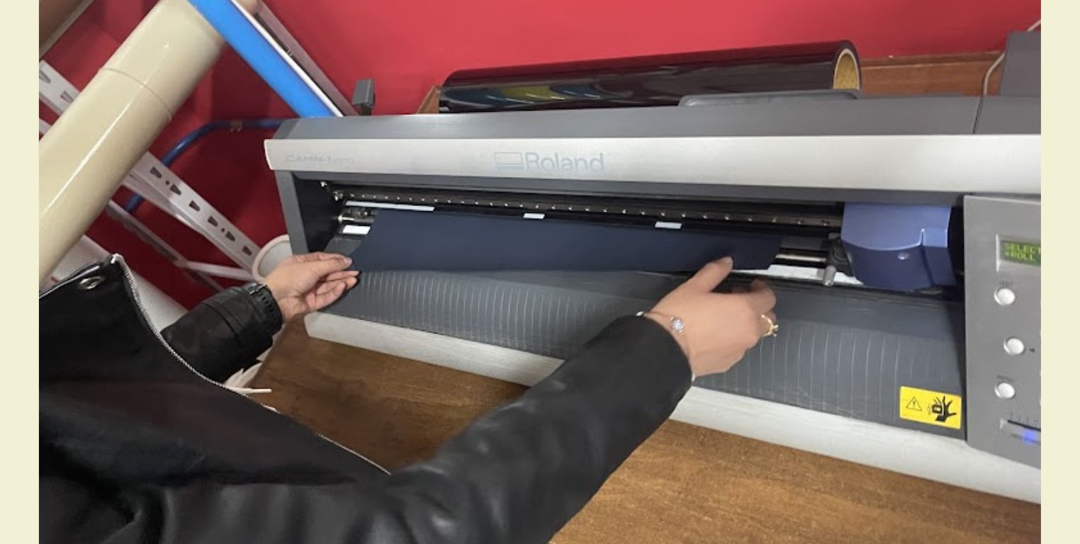
- To start the vinyl cutting I arrived with my file, and the first thing I did was to turn on the machine.
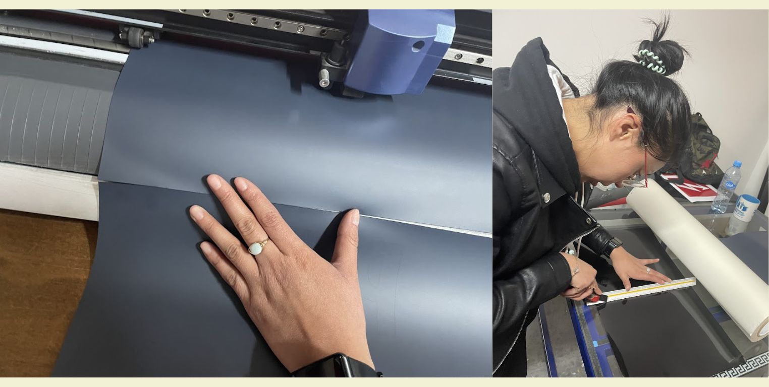
- Then I chose the color of vinyl I wanted to cut the letters.
- The next thing was to set it up. This has to be put with the matte color on top and the glossy material underneath.
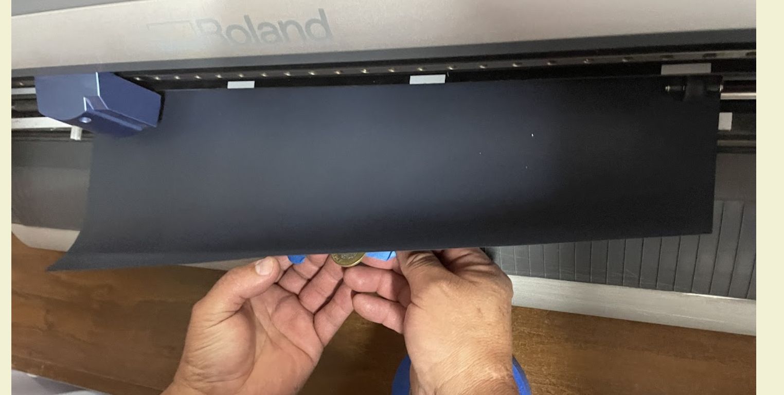
- As a TIP, in the case of the black textile vinyl, it reflects the machine, so you need to put some weight on it so it can cut correctly.
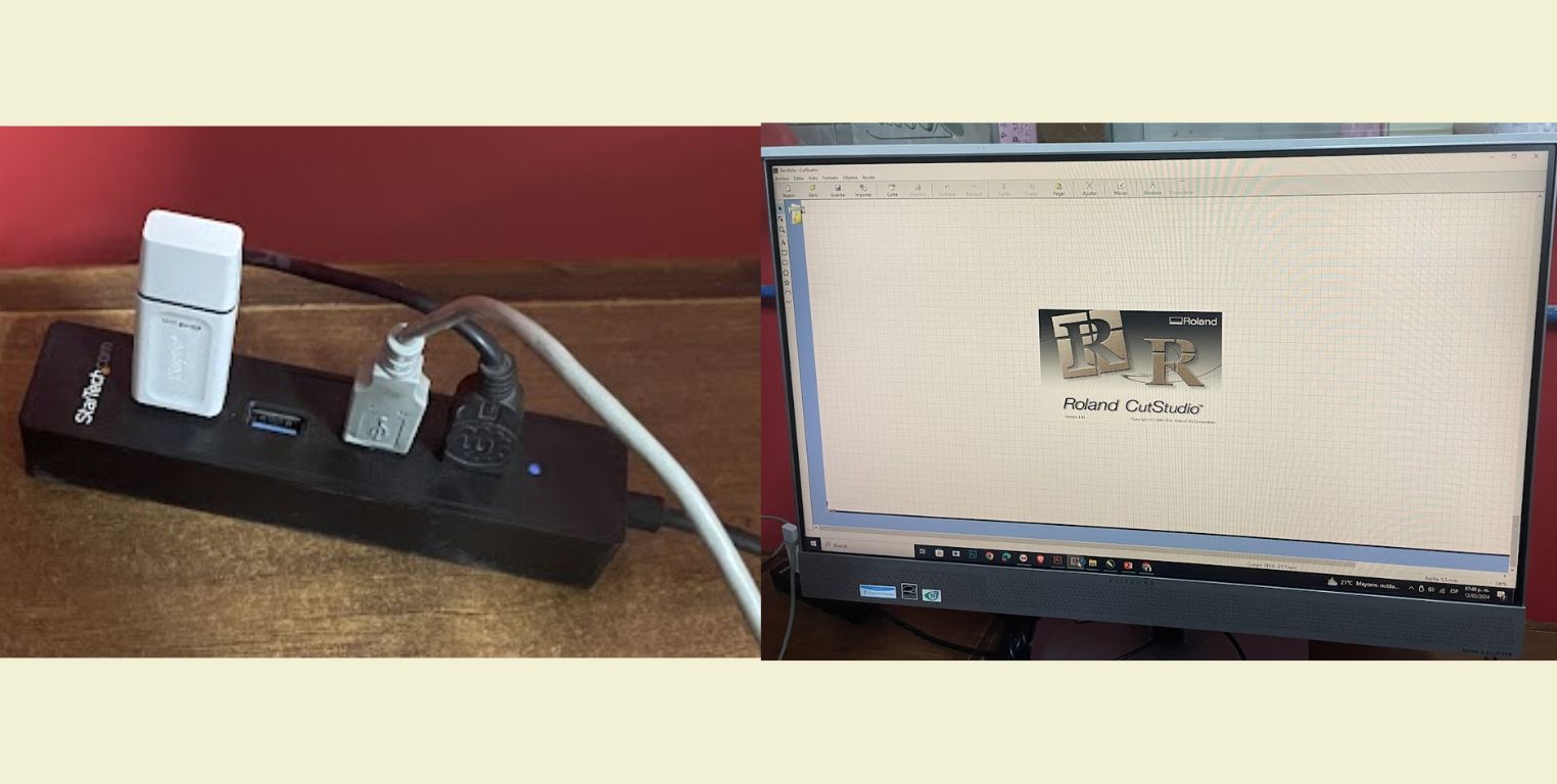
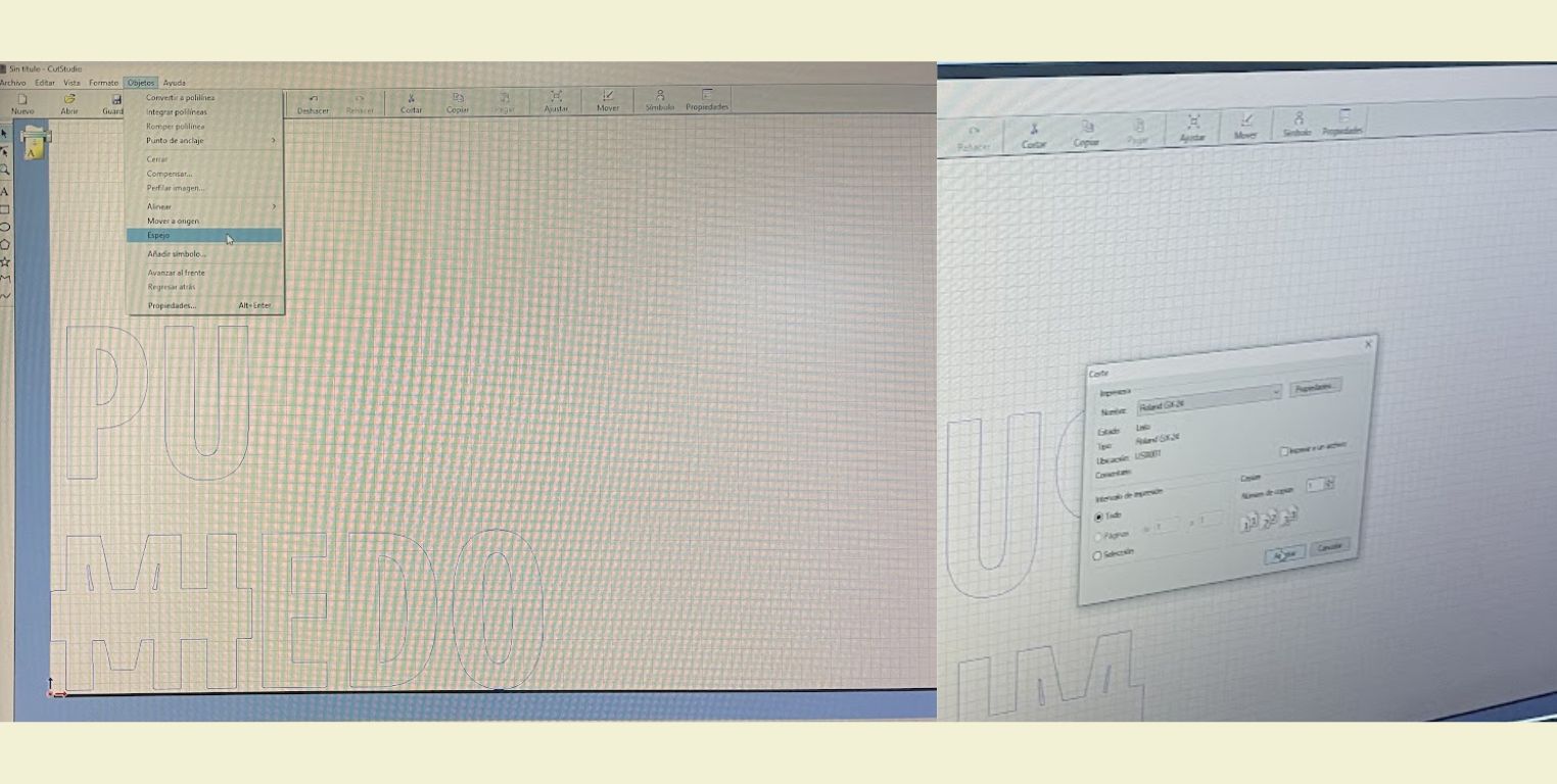
- I then plugged in my USB and opened the program called "Roland CutStudio". This is the program that runs the vinyl cutting machine we have at IDIT.
- Once in the program I opened the EPS file. It is important to have the file type selected
- Once opened, I ungrouped the letters and removed some lines to ensure that the cut was clean.
- Then, as it was going to be cut in textile vinyl, the text had to be reflected, so I selected everything and in object I changed it.
- Then in the machine I pressed "origin" so that the machine would size it.
- I went back to the program and sent it to cut. Actually this step is not very complicated, it is something that can be learned quickly.
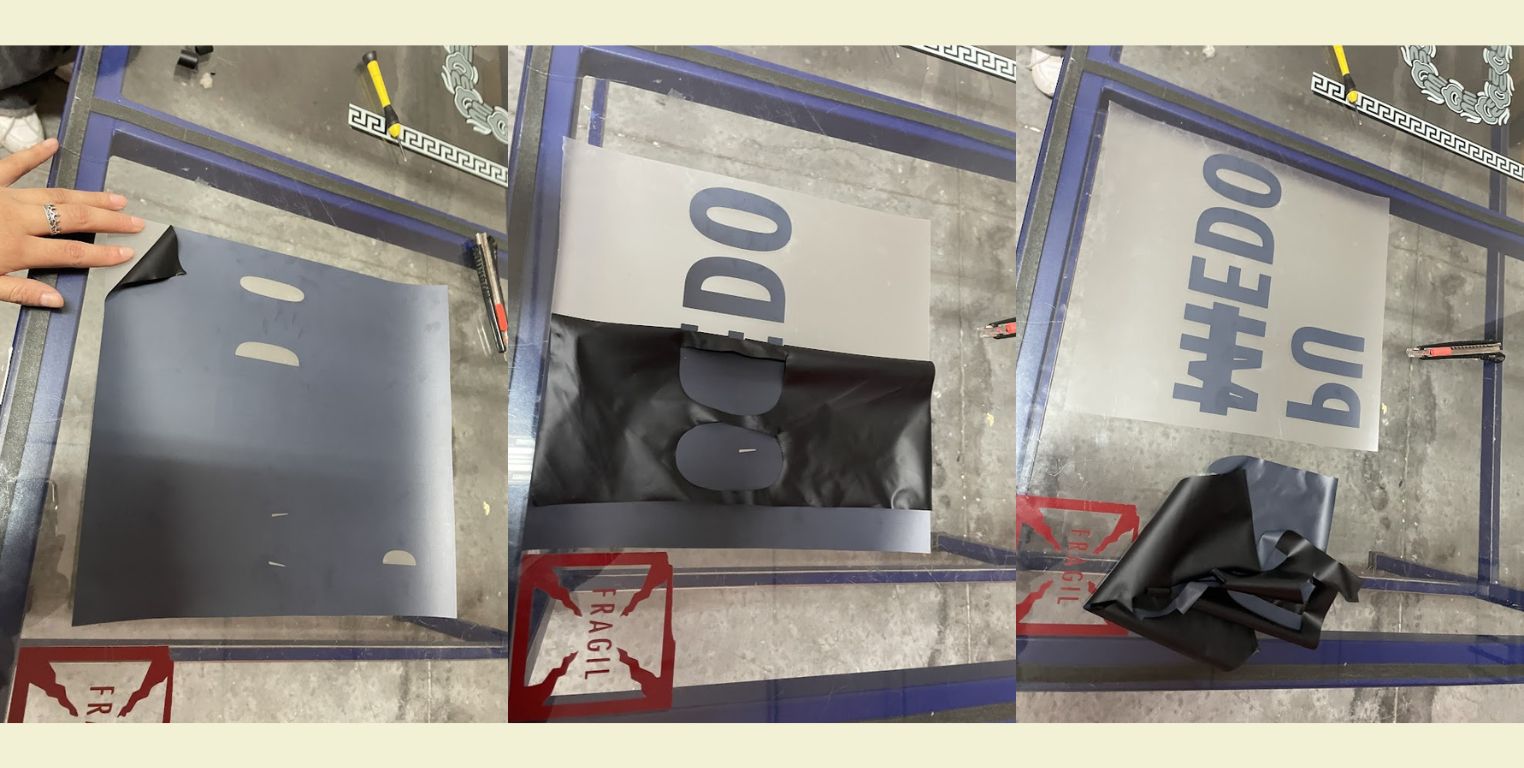
- After that, the only thing left to do is to separate the vinyl cut from the roll. For this, the machine has a hole along the length where the cutter easily enters to do the job. After this step you can also remove the excess vinyl you don't need.
Making sublimation on a blanket bag!
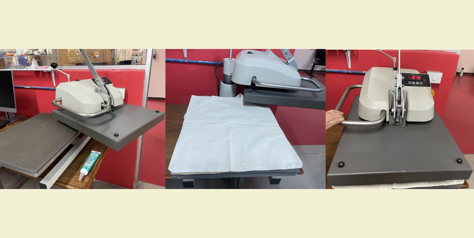
- The first step was to turn on the machine and heat it to a temperature of 150°.
- While it was heating up, I removed the background of the letters I didn't need, so I could keep only what I did need on the clear film.
- After leaving it heating for a short period of time I placed the bag on which I wanted to do the sublimation and lowered the machine for about 15 seconds (this so that it would iron).
- Then on top I arranged it in a shape that I liked the letters.
- When I was sure of the position I lowered the machine for about another 15 seconds so it would stick.
- Once I removed the machine again from the bag, I waited for it to cool for a few seconds and then I started to carefully remove the transparent film.
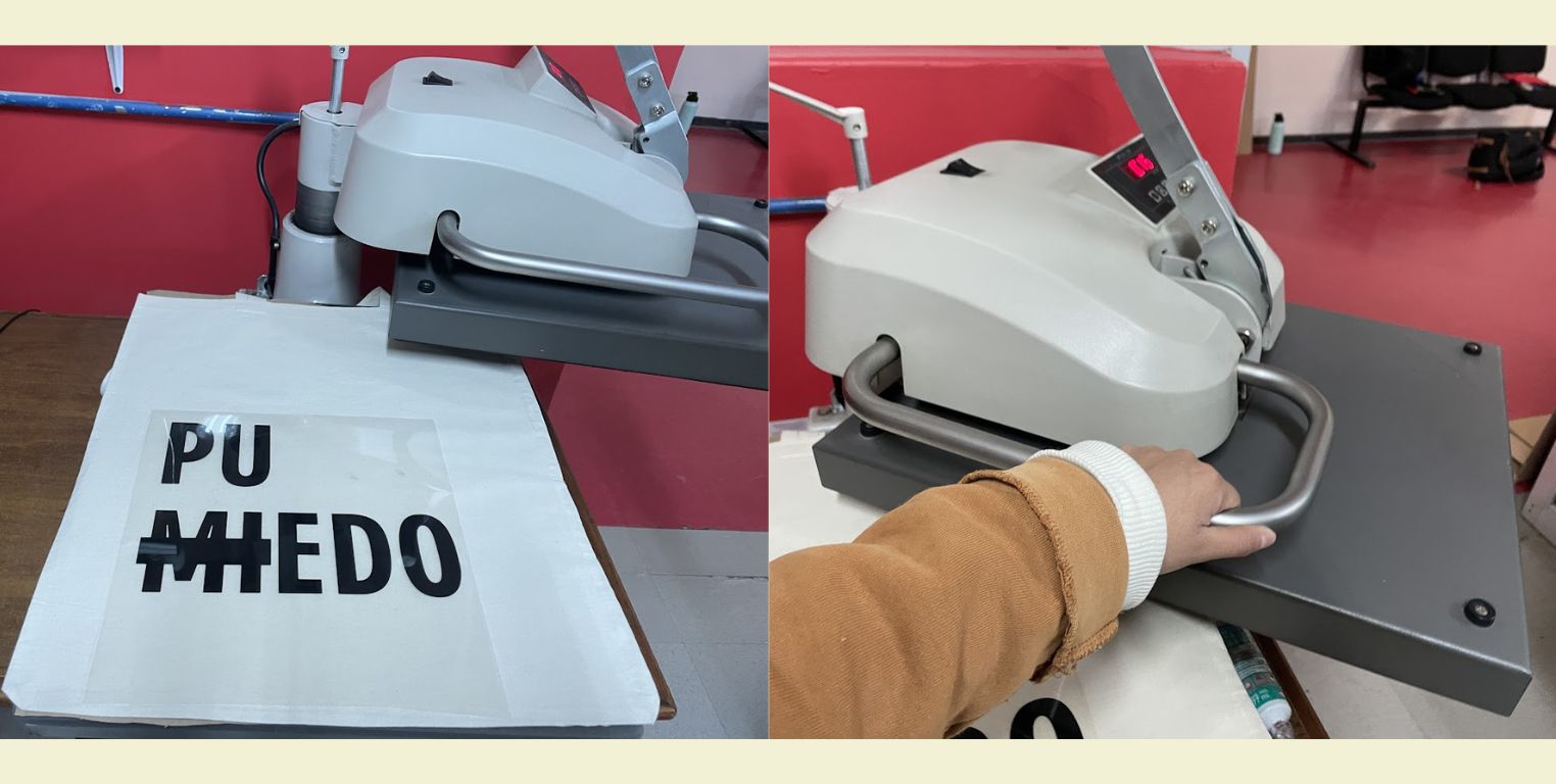
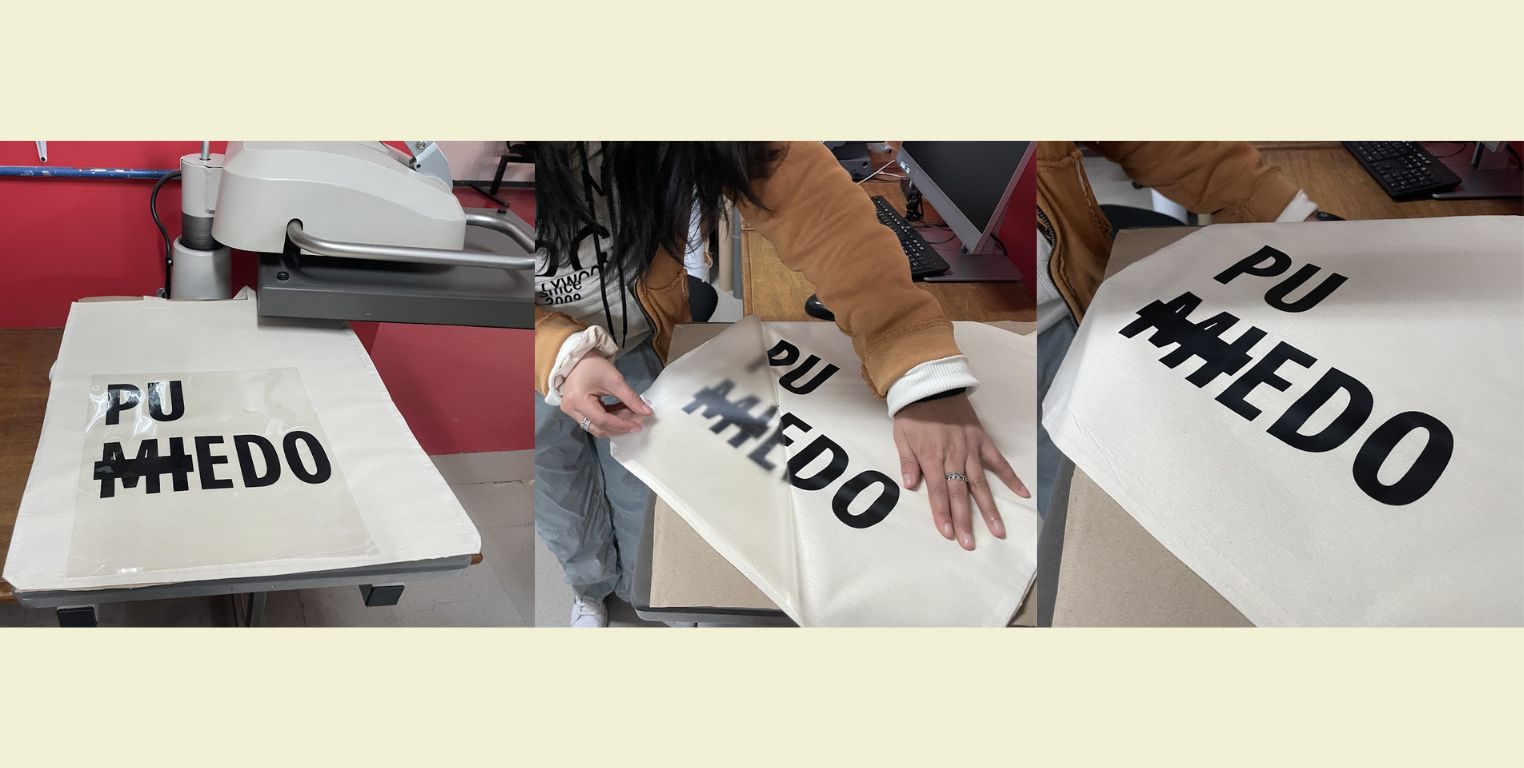
And well, now you can see the final result!
Conclusion
This way of doing things really facilitates a lot the work and reduces the time. However, when it's your first time doing something parametric it doesn't always come out as you expect (my case), so here are some TIPS:
- Make sure your drawings are parametric from the first moment you give the parameters, this helps you to correct mistakes early without having to redo everything you did before.
- Make cutting tests, this allows you to rectify measurements if necessary without sacrificing a lot of material.
- Always think that you will take twice as much time, do not overestimate the time you will take because situations can always occur that lead you to take more time than you thought.
On the other hand, knowing how to take advantage of this type of machinery is really advantageous for rapid prototyping, as well as facilitating the production of other products.
Always try and remember that EVERYTHING CAN BE REDESIGNED.