WEEK 2
COMPUTER AIDED DESIGN
For this week the homework was to develop a 2D and 3D model with a computer aided design program. As far as programs that allow me to develop the construction of a 3D model from a 2D drawing on it, I have experience working with Inventor, SolidWorks, Rhinoceros and recently I am learning Fusion 360. So those are my tools for the battle.
This time my challenge was to finish with the render of my final project, so with that in mind I decided to choose between the two programs that I consider I have more experience, and about it I listed what I wanted to achieve with the program from most to least important to decide for one.
| Ease of modeling organic surfaces | I am interested in exploring the shape of my lamp body | Rhinoceros |
| Ease of modeling without the need to know dimensions | Although it is relevant to me I am still iterating on averages, so it is not my priority at the moment | Rhinoceros |
| Technical drawing generation | Both programs have this option, however, it is not the forte of both | SolidWorks |
That's how I came to decide on Rhino, although now with the base, I don't see why I wouldn't use SolidWorks in the future, or even Fusion 360, even though I'm just exploring its features.
 Rhinoceros
is a NURBS-based 3D modeling program, which means that it uses mathematical representations of
geometry
for the creation of curves and surfaces, making it quite noble for organic bodies.
Rhinoceros
is a NURBS-based 3D modeling program, which means that it uses mathematical representations of
geometry
for the creation of curves and surfaces, making it quite noble for organic bodies.
If you don't have Rhino, you can download the full free trial for your PC as I did in the followinglink. In this case I am using version 8.
Let's make a 3D model step by step!
-
To start I opened a new file in Small Objects – Millimeters. And activated the record history.
-
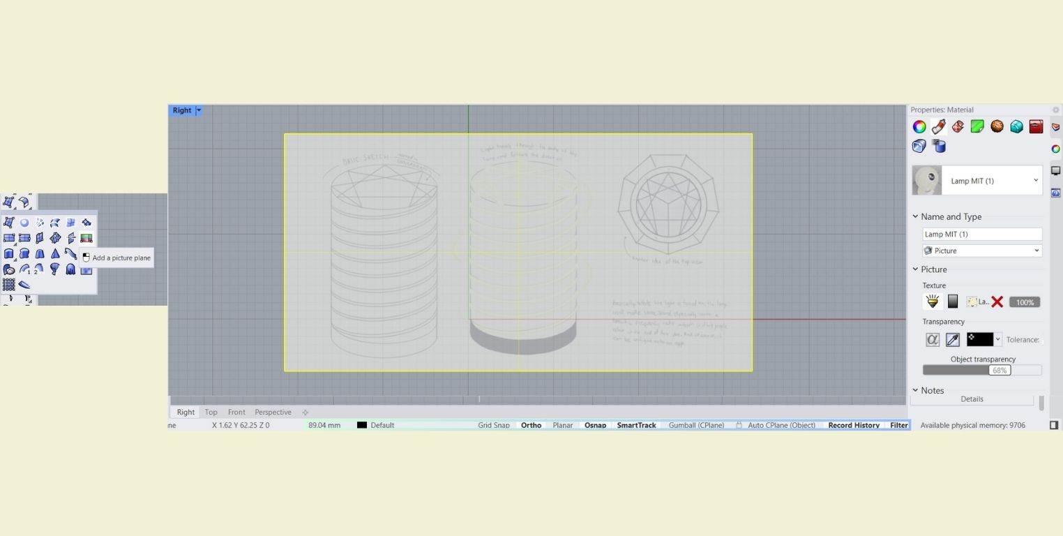
Then I inserted the quick sketch I made last week with the "Add a picture plane" tool in the "Right" view just to have it as a reference for the light spirals. And in the "Properties: Material" part I lowered the opacity.
-
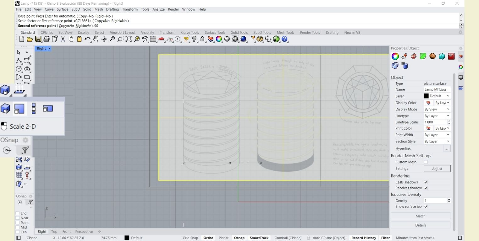
I took 90 mm as a guide to scale the base of the lamp.
-
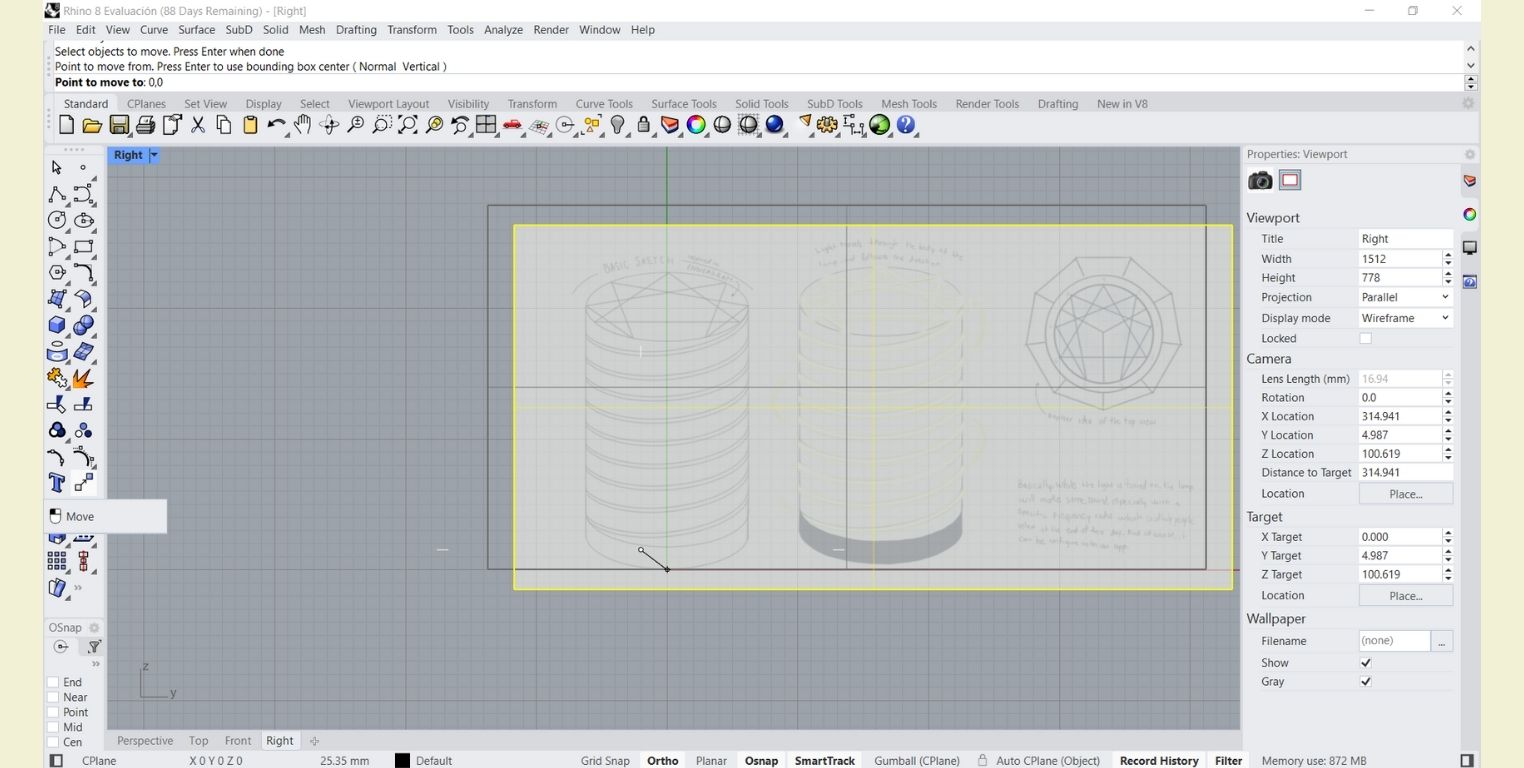
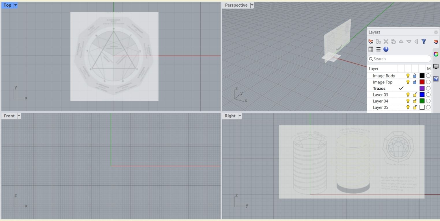
To be more precise in the workspace, with the "move" tool I located the base of my drawing that I wanted to move to 0 in X and Y. In another layer, I put another image in the top view, following the steps before.
-
I renamed and locked each of the layers with images so that from this point on I could make slices without worrying about the base images moving.
-
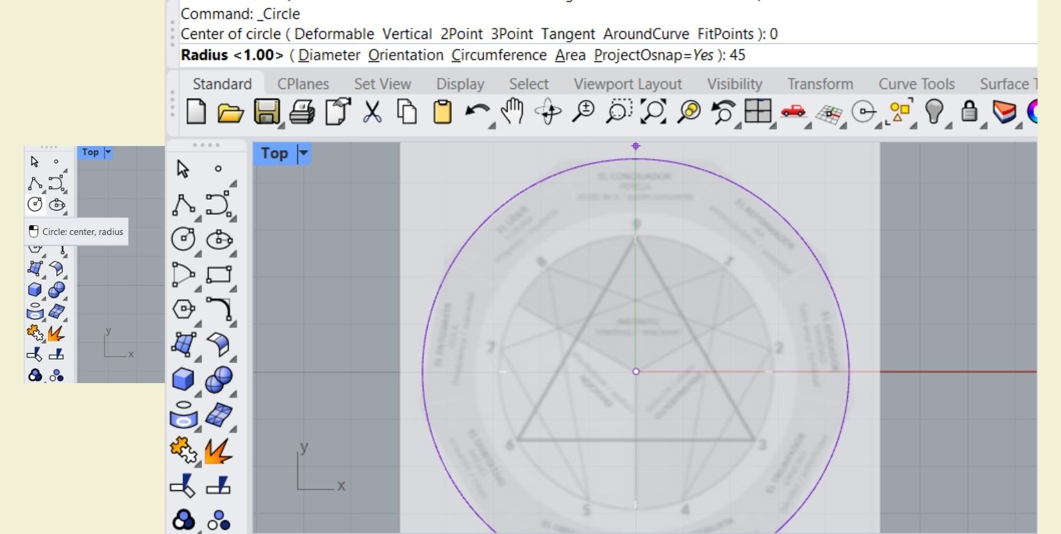
In my Top view I drew a circle with center at 0 and a radius of 45 mm.
-
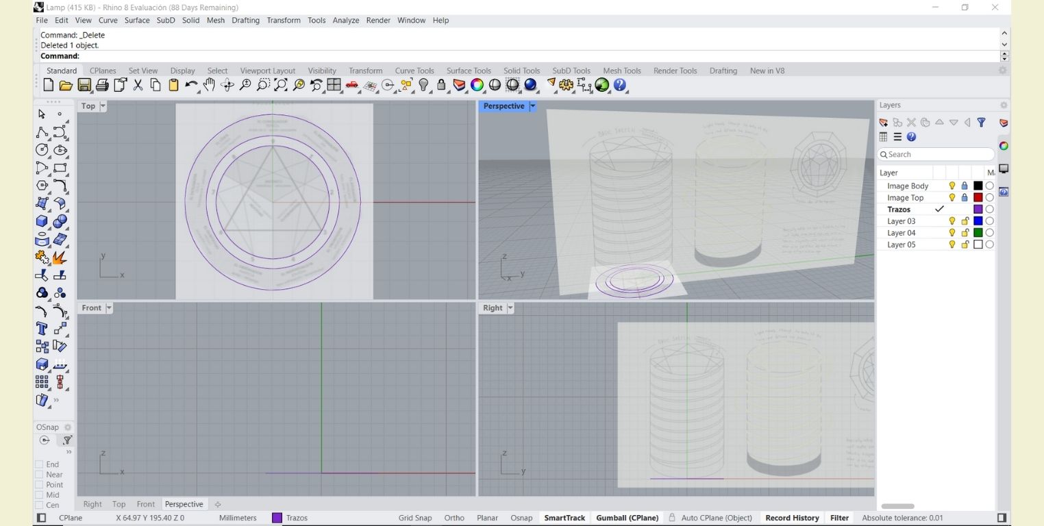
I successively drew two more circles taking into account the base image.
-
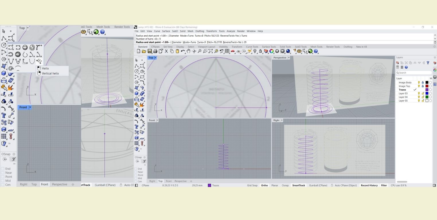
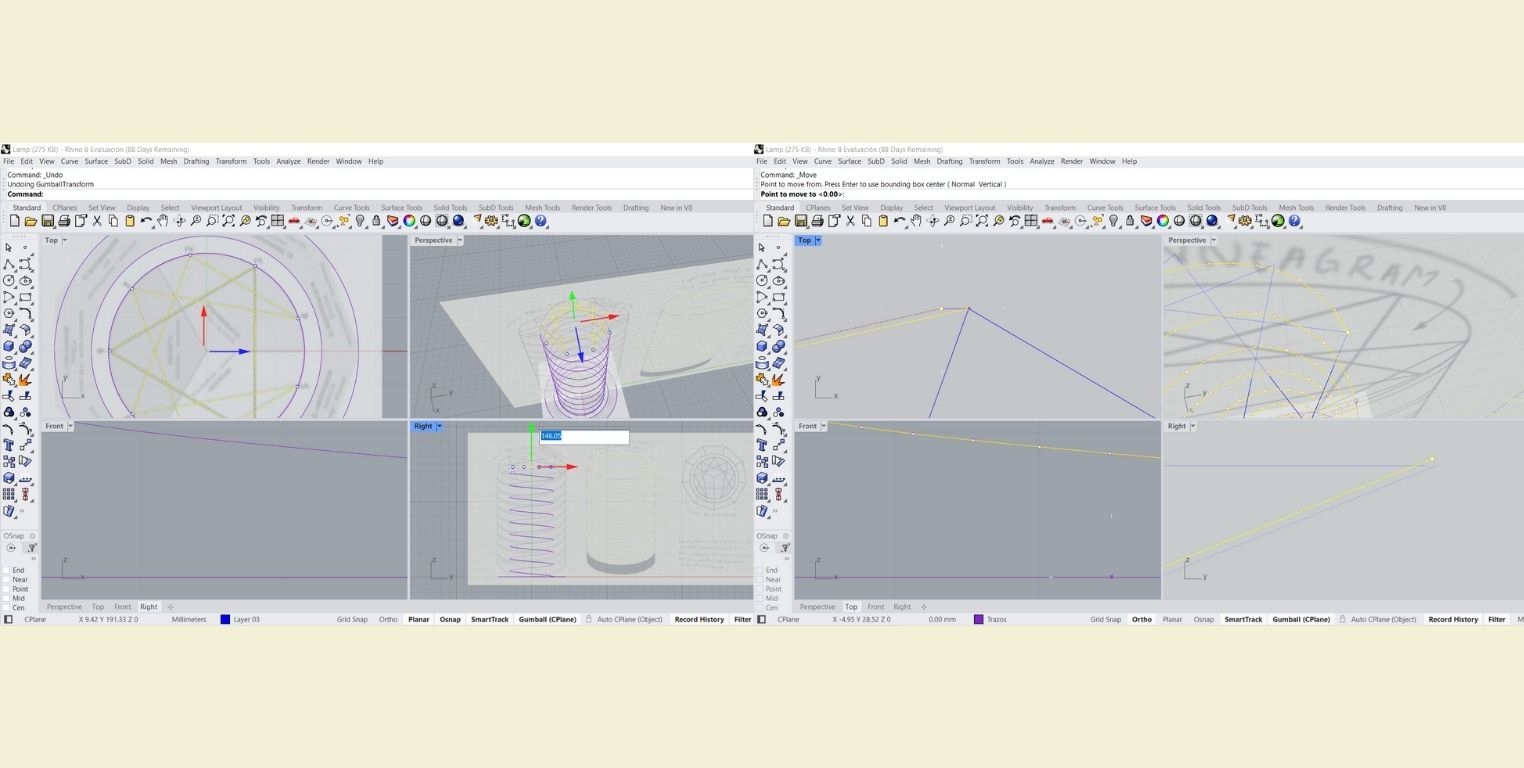
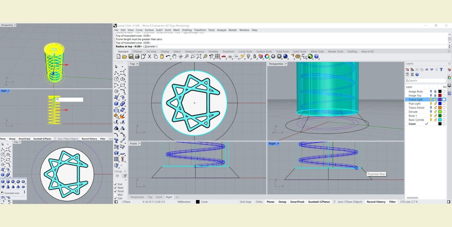
With the help of the "helix" tool I made a spiral starting from 0, with a height of 146.05 mm. In "turns" I changed the value to 9 for the 9 levels that I want the lamp to represent, and finally the radius that it asked for I put it according to the smallest circle, which has a radius of 29 mm.
-
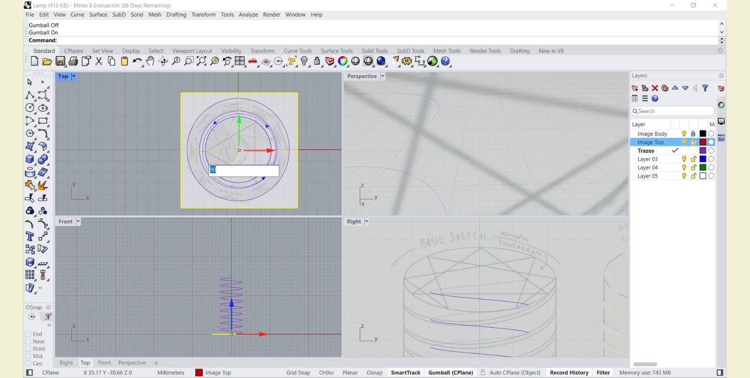
For practical purposes I rotated the top view image. This is easy with "Gumball" activated. In this case I made a 90° rotation.
-
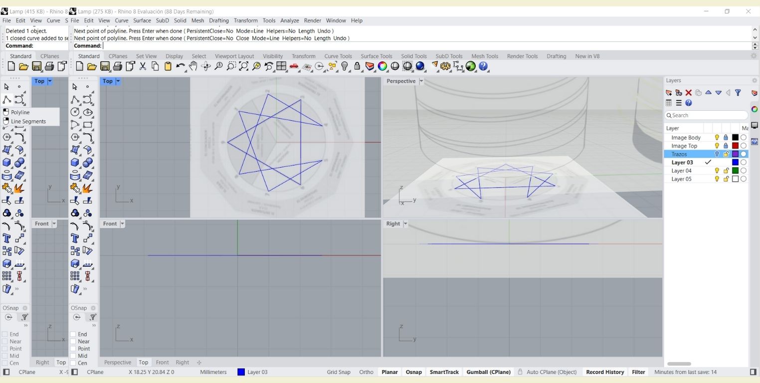
Once in place, I switched layers to start tracing the Enneagram figure, taking care that the points that had to touch did touch.
-
I raised with the help of the "Gumball" the previous strokes to a height of 146.05, the same height as the spiral, so that later with the "move" tool I could move millimetrically the end of the spiral to the nearest point of the Enneagram figure, this can be easier and more precise if you have activated "SmartTrack".
-
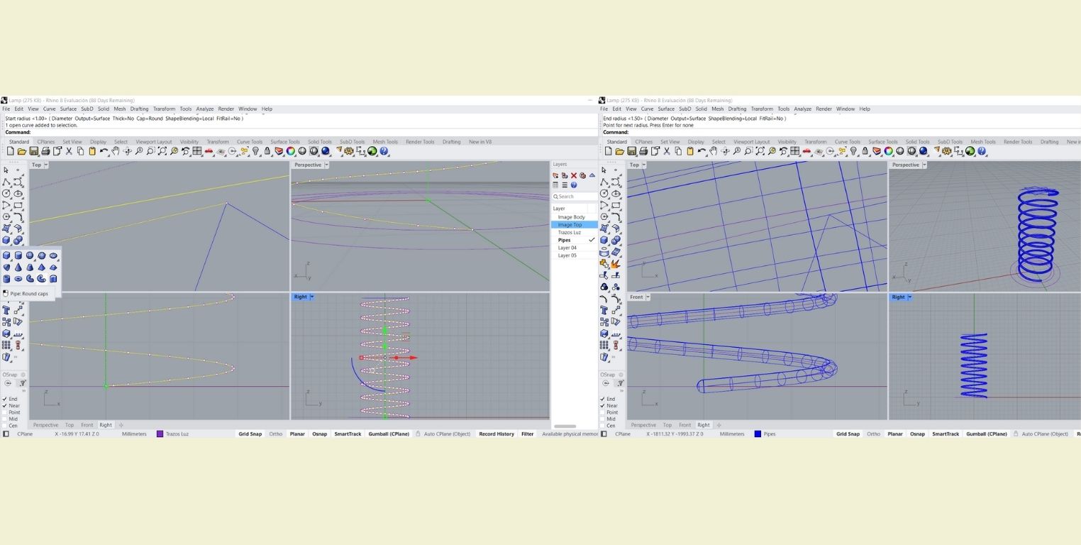
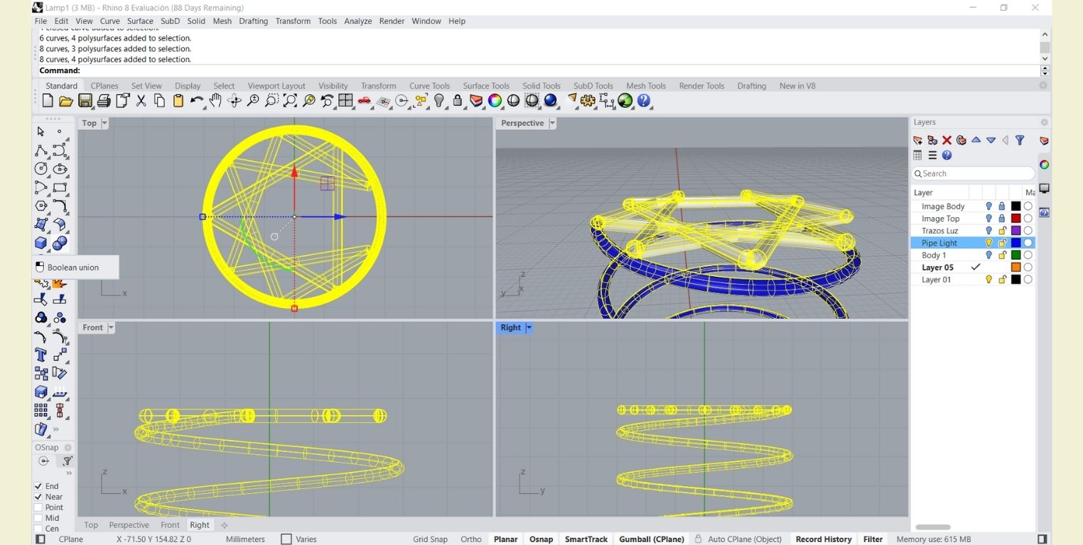
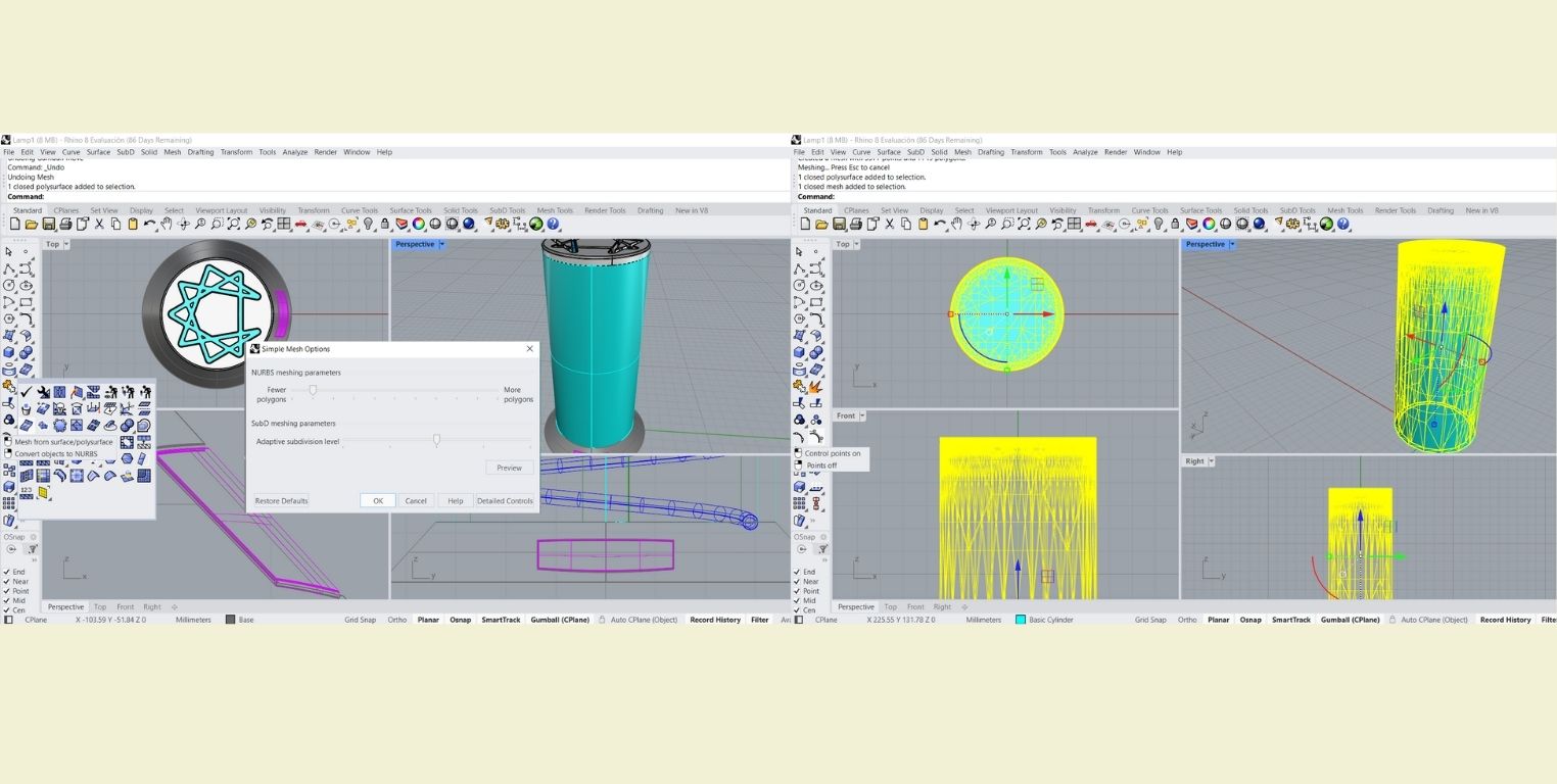
Once I made this adjustment in the spiral, I made a "Pipe" of 1.4 radius in the highest part and of 1.5 radius in the rest of the body. This pipe will help me to simulate the light spiral of the lamp.
-
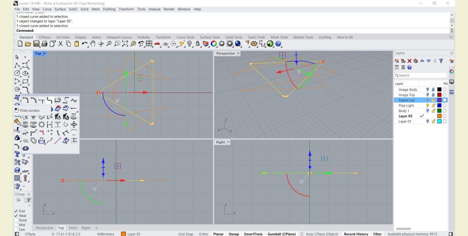
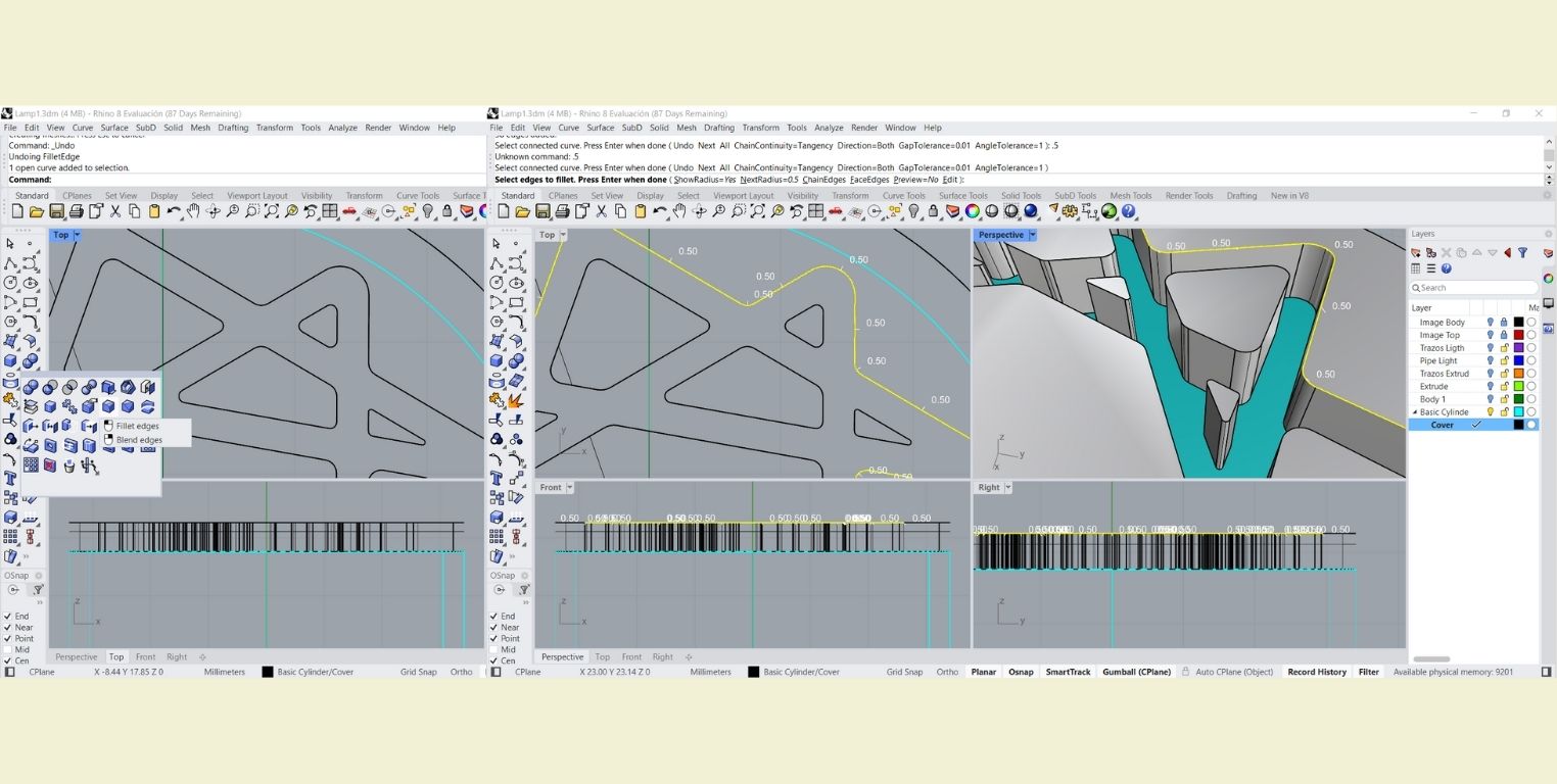
Before doing the same with the Enneagram stroke, I copied and pasted it in another layer, this only with Ctrl c and Ctrl v. Done this I made a rounding to each stroke with the "Fillet corner" tool with a radius of 0.5mm. Once done, I proceeded to make a pipe of 1.5 mm radius as in the previous step.
-
I proceeded to join the Pipes made with "Boolean union".
-
In a new layer called "body 1" I made a cylinder from the center whose radius would touch the inner circumference of the ellipse and whose height would reach the base of the pipe of the enneagram shape. This to simulate the support that the light will have.
-
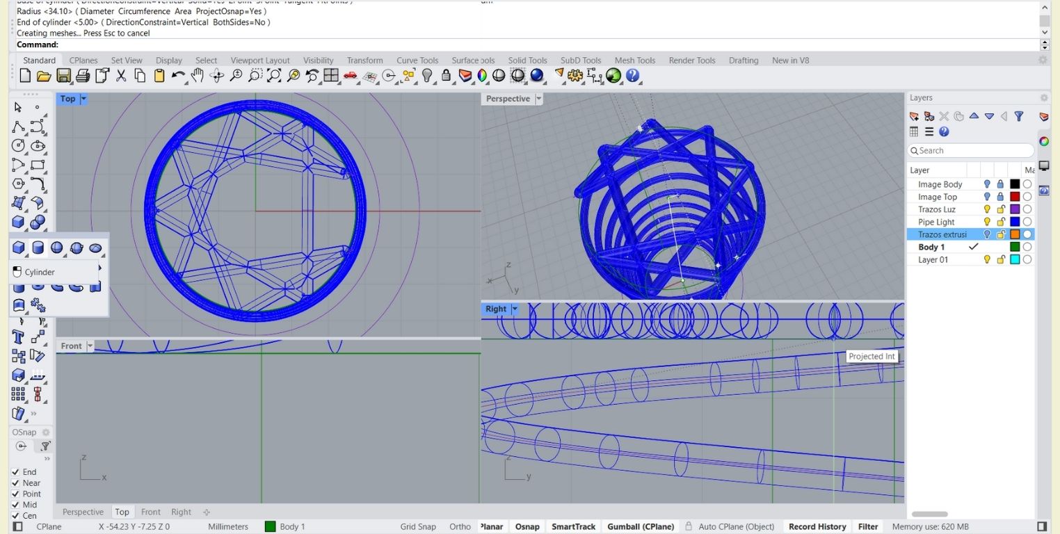
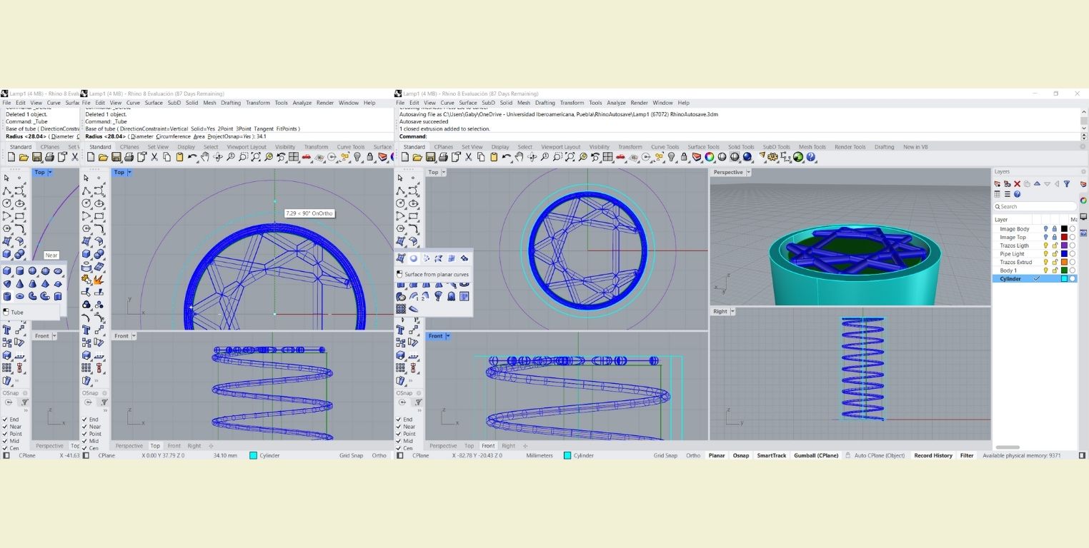
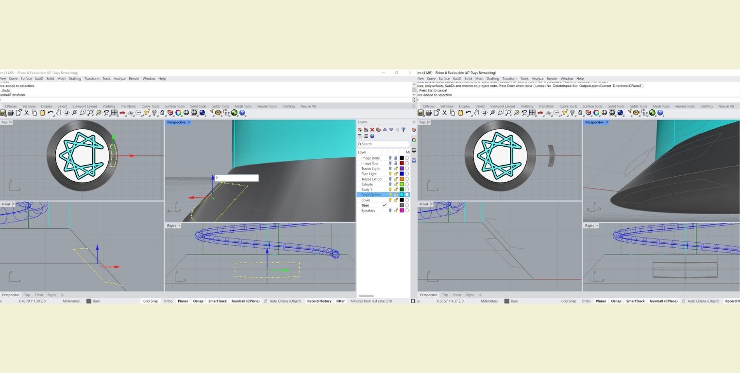
In another layer I made a "Tube" whose first circumference touched the outside of the pipe figure, and the second one touched the next circumference that in the photo is shown in blue. The height was set up to where the pipe reached.
-
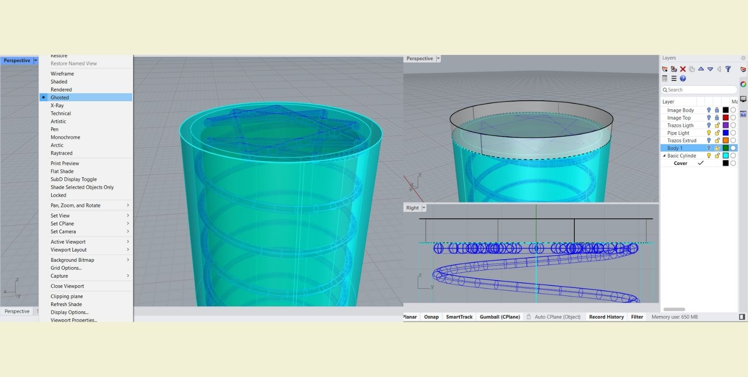
Then I covered the tube with a cylinder of only 0.1mm of height and I joined it with "boolean union". This last I repeated it again to make the lamp cover, but I made the height 5mm.
-
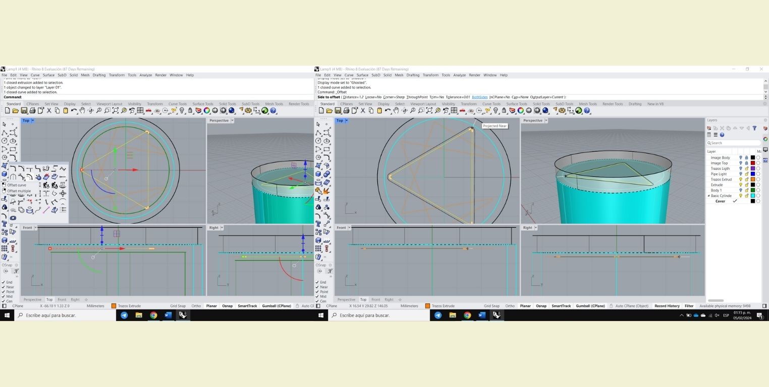
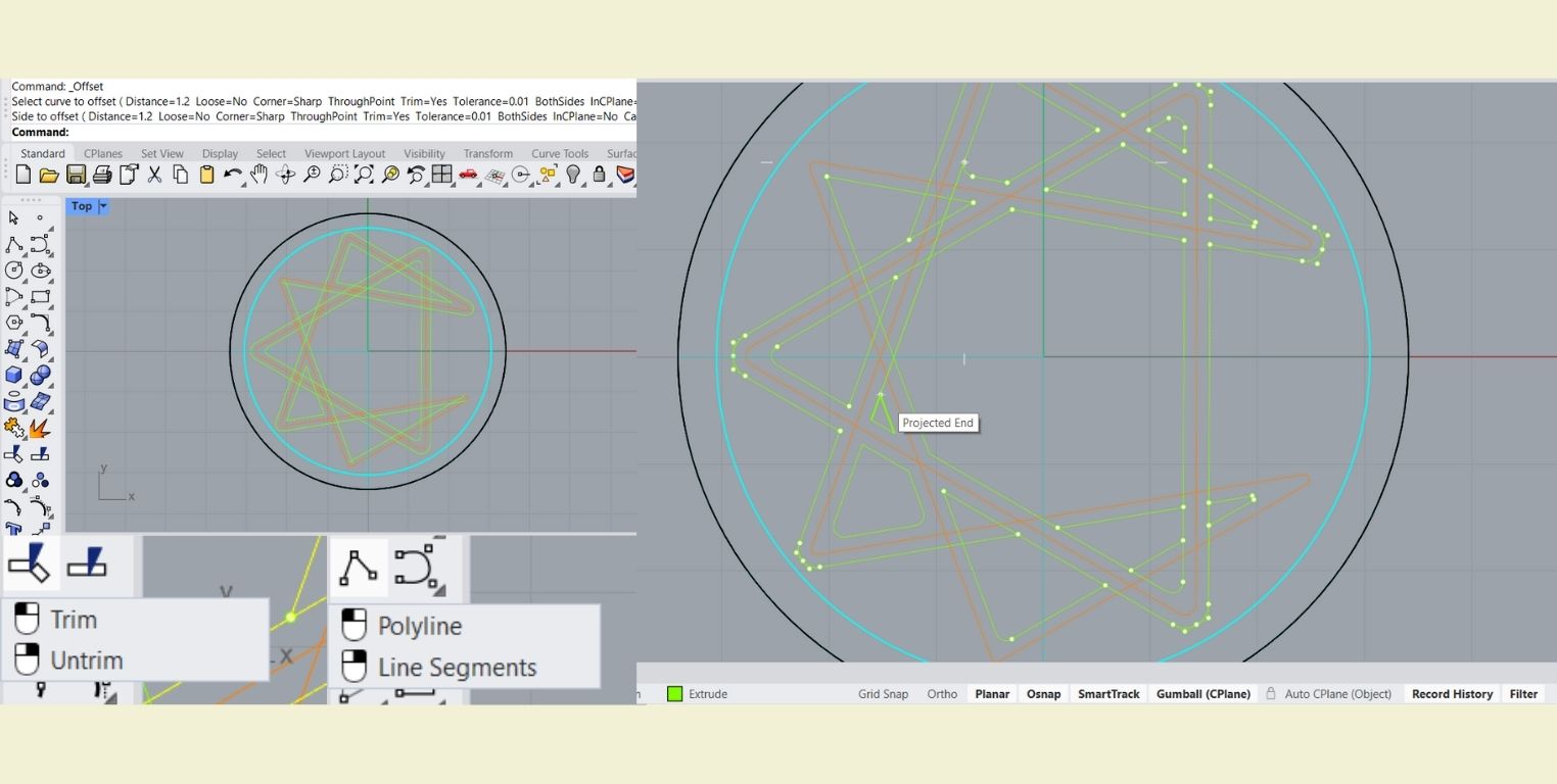
The next step was to take the traces of the enneagram figure and I made them an "Offset" and selected "BothSides".
-
I moved those last traces to a new layer to differentiate them better and with the "Trim" tool I started to cut the excess lines that I had generated. With "Polyline" I made the missing curves on one side only. It was helpful to have "SmartTrack, Planar and Osnap" activated.
-
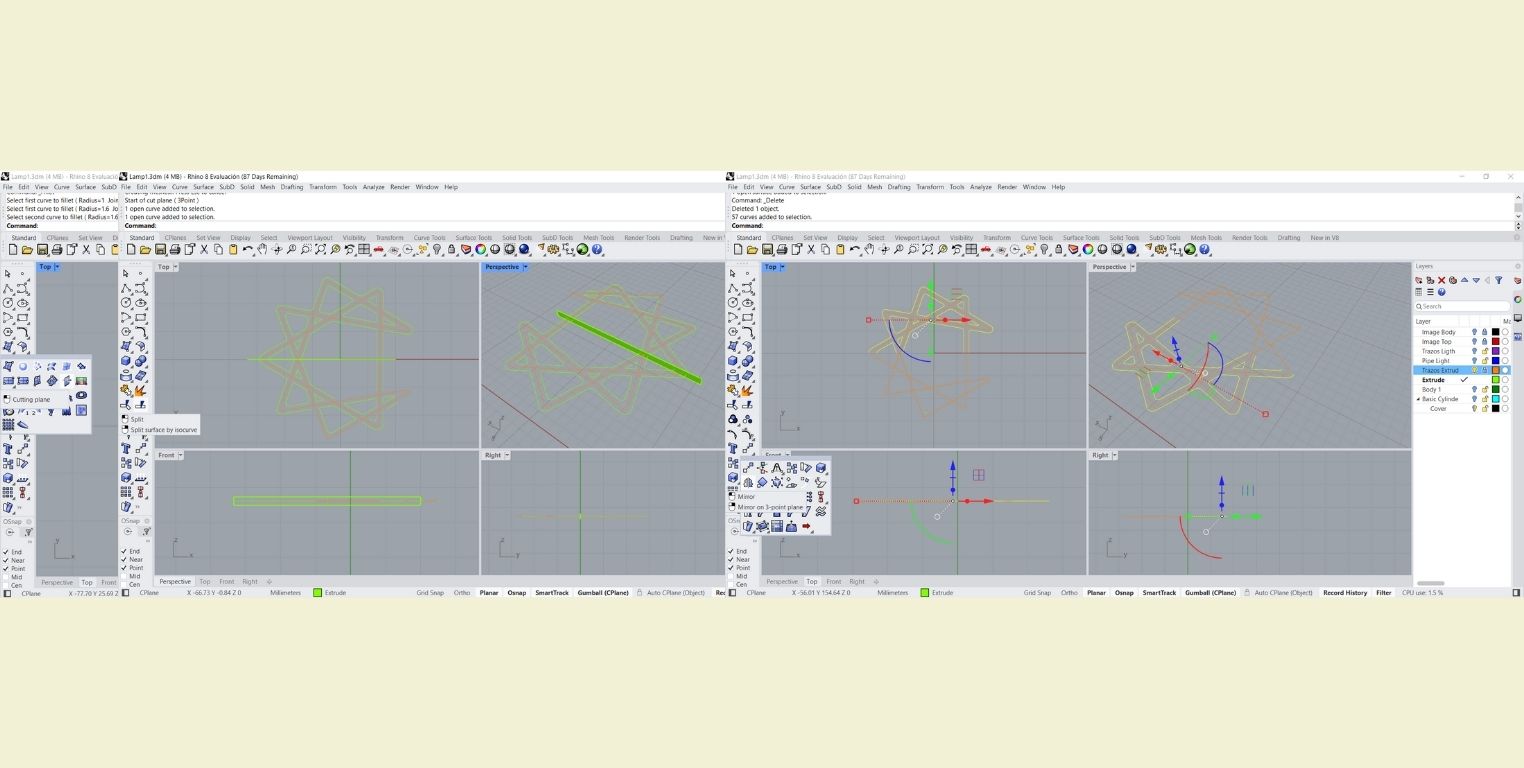
Once ready I made a "Cutting plane" right in the middle to cut the lines with the "Split" tool, delete the ones that were not useful and then make a "mirrow".
-
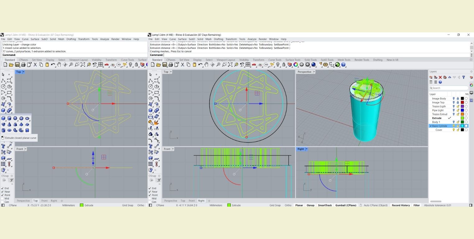
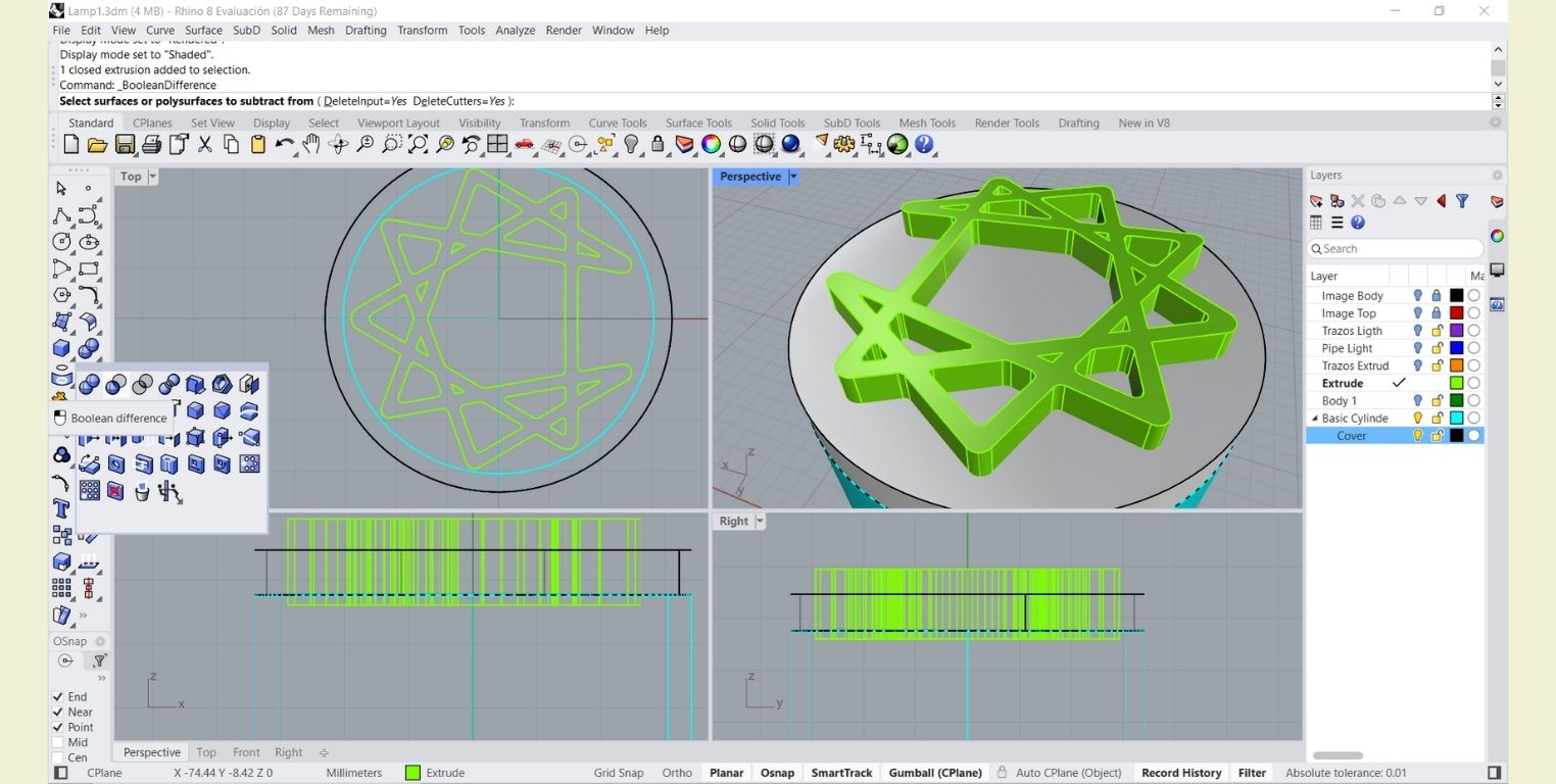
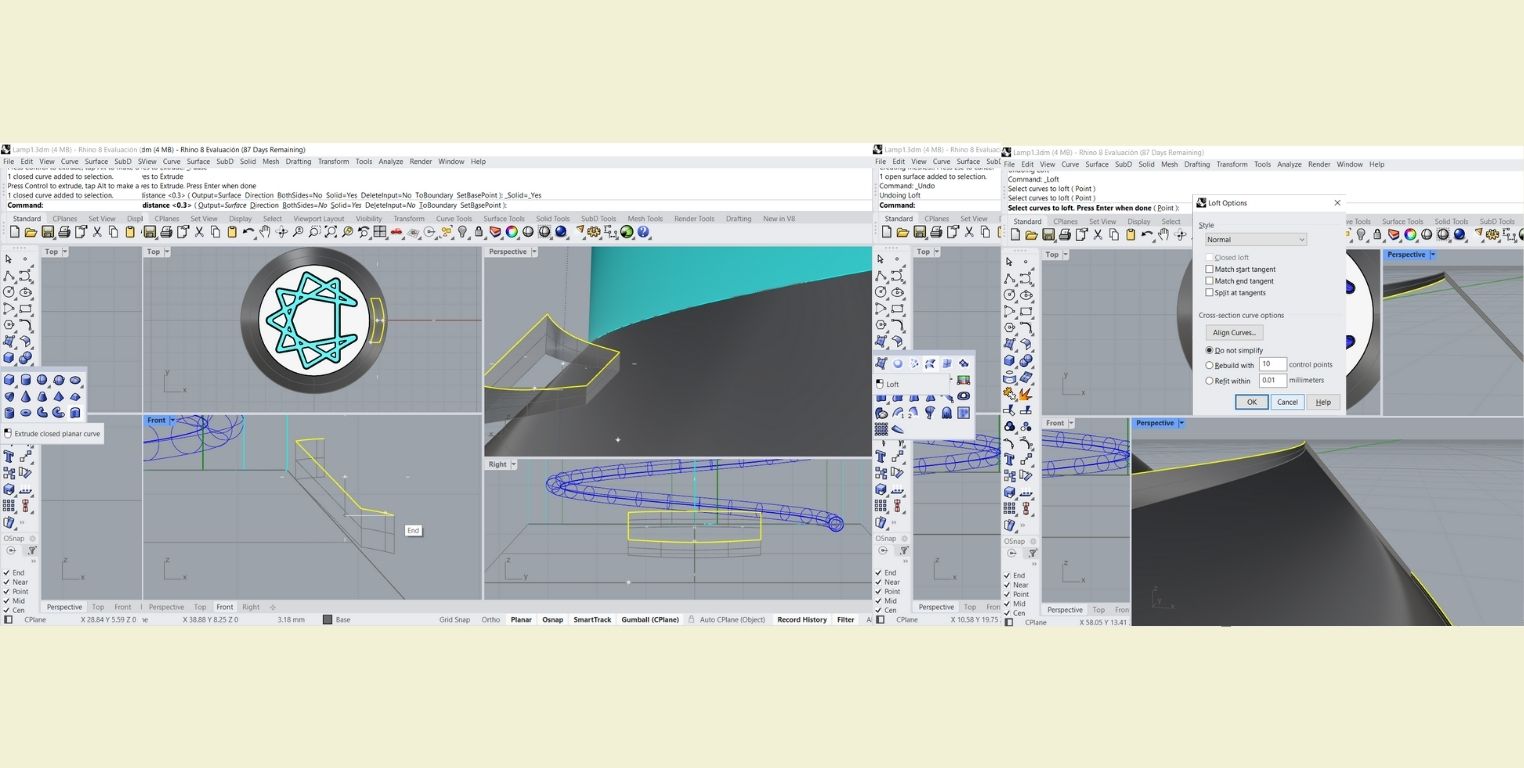
I extruded those lines upwards with the "Extrude closed planar curve" tool, just enough to pass both ends of the cover I made before.
-
That extrusion helped me later to make a "Boolean difference". First I selected the surface on which I wanted to make the cut (the cover) and then the surface that would make that cut (the last extrusion).
-
To the remaining surface I applied "Fillet Edges" to smooth the cuts.
-
With the help of the "Gumball" I raised the whole model enough to make the base, which I did with "Truncated cone". As a guide I used the curves that I drew at the beginning, and I used the biggest one for the base.
-
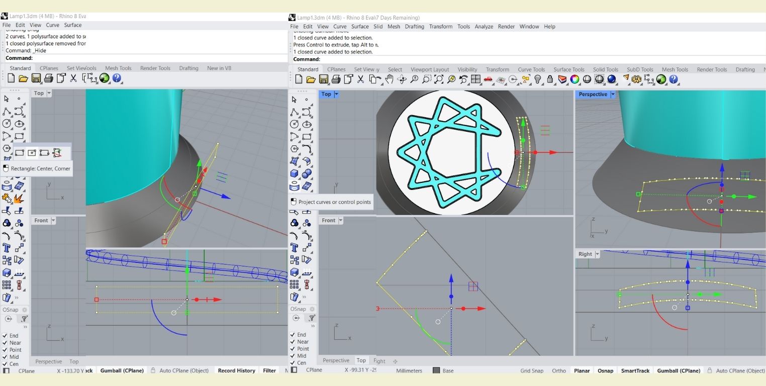
In the Rigth view I drew a rectangle and then used the "Project curves or control points" tool on the base. However, it projected in the wrong direction, so I became best friends with "Gumball" to rotate the stroke and put it the way I wanted it.
-
When I had it in the right direction I moved it up a bit with "Gumball" (my new best friend) and reapplied the "Project curves or control points" tool to make sure it was glued to the base.
-
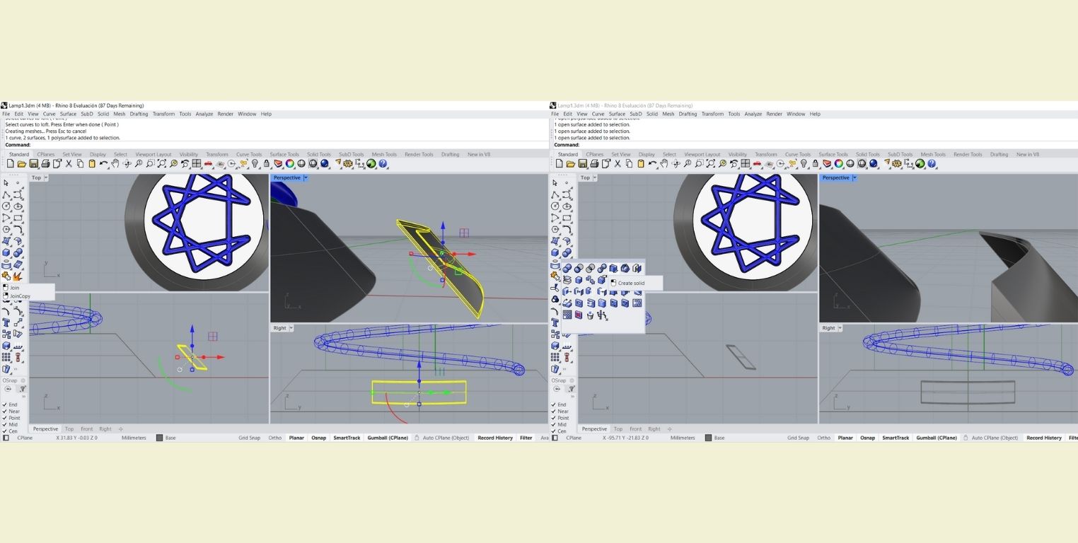
To better visualize what I was doing I moved up the last curve I projected and extruded it down 0.3 mm. Next step, I made a "Loft" to make it look like a closed figure.
-
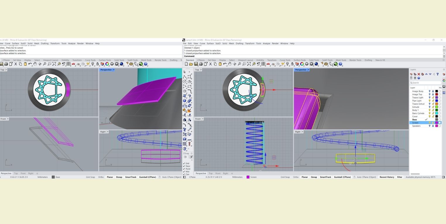
I selected what I did in the previous step and applied "Join", followed by "Create solid". And I lowered my piece again and then applied "Boolean difference" with respect to the base and kept the cut surface. With this I have the screen and the space for the screen.
-
Again I raised the piece for a better visualization and with "Fillet edges" I smoothed the screen space and the screen itself. Then I lowered again the piece that I raised.
-
Due to time I could no longer play and change the boring cylindrical shape, so I applied "Mesh" to the cylindrical base. Then I applied "Control poitns on". I realized that I had generated another body on top of it, so I worked with the second one.
-
In the new body I selected groups of points and with the help of "Gumball" I edited them to modify a little the shape of the cylinder, but without deforming it too much.
-
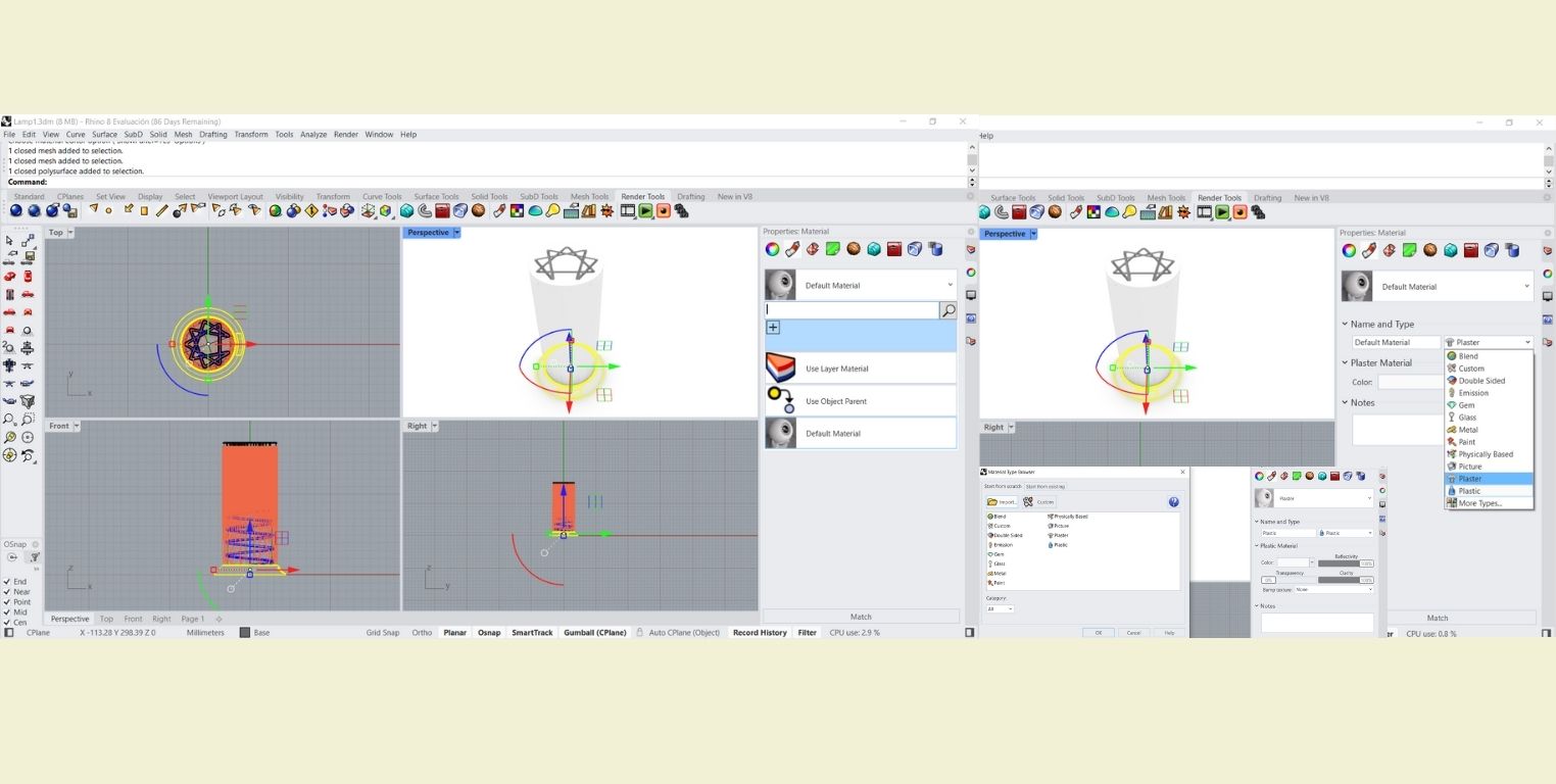
I applied materials in the "Properties: Material" part. If you click on "More Types" you can click on "Import" and discover more materials.
-
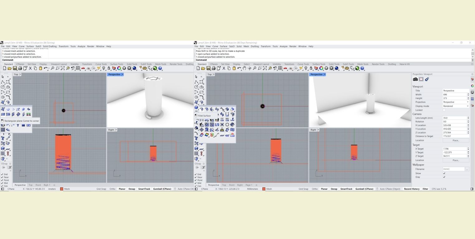
For the background I only used the tool "Rectangular plane: Corner to corner" and then I applied "Fillet Surface" between each plane.
I insert some pictures of the final result.
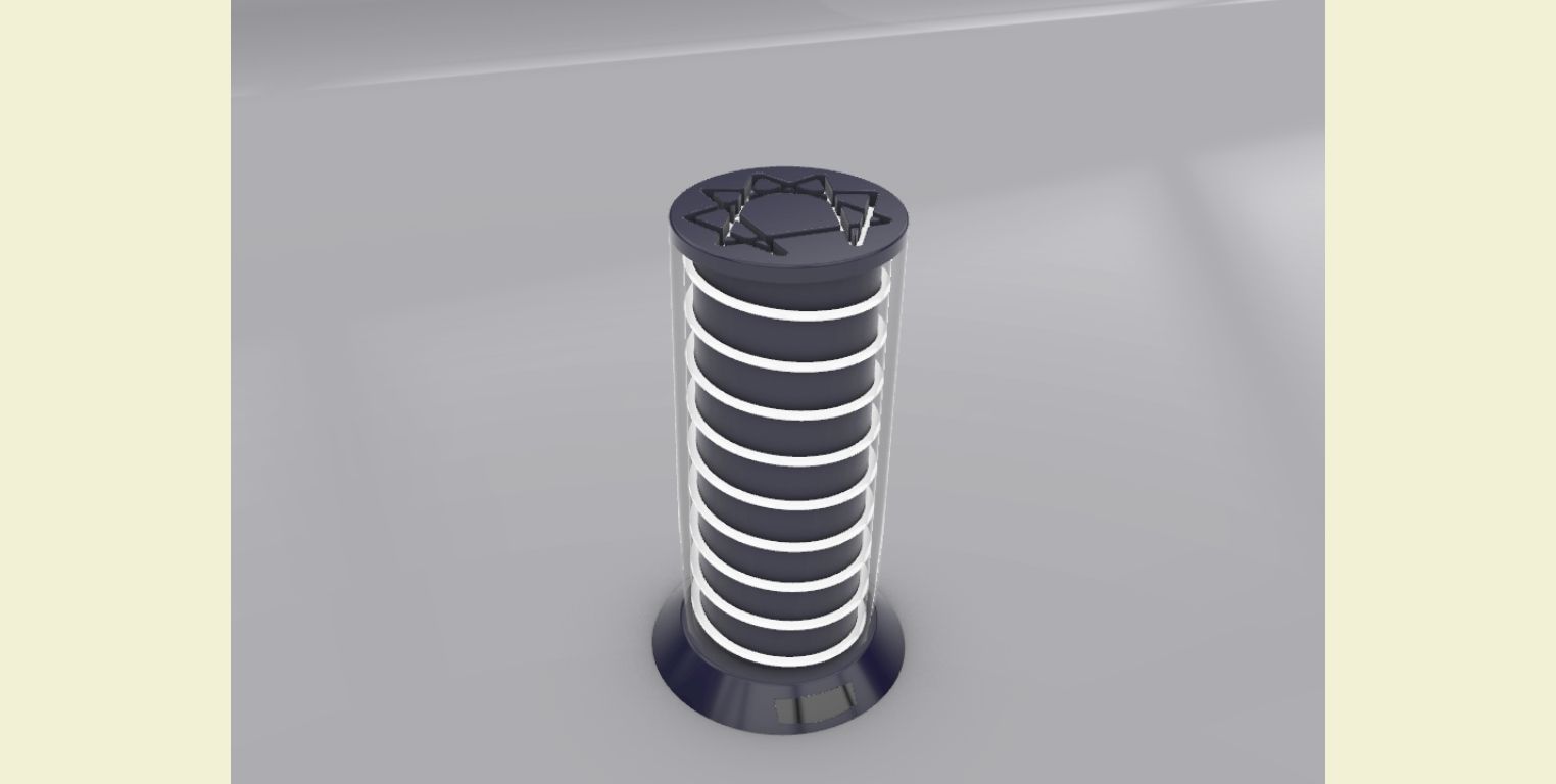
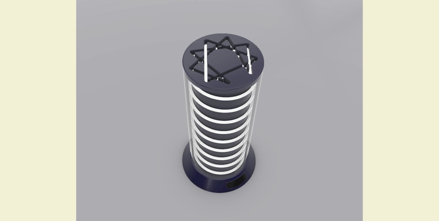
3D Model
TECHNICAL DRAWING
Taking advantage of the fact that Rhino allows you to make 2D drawings, I elaborated the technical drawing of my model.
You can find the files ready to download in the File area.
-
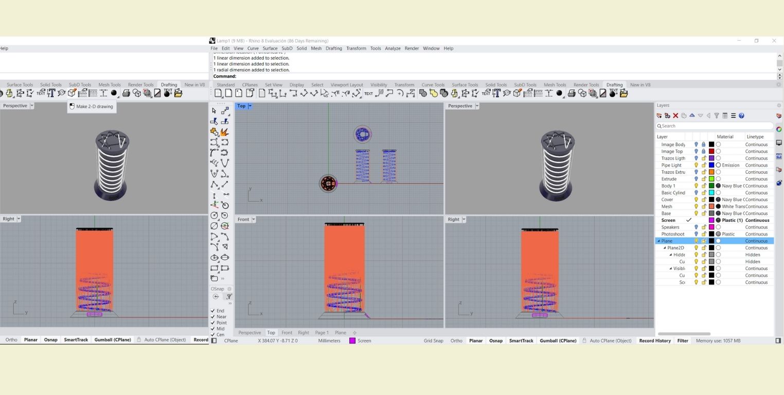
In the "Drafting" tab I used "Make 2-D drawing" and applied it to my entire model. Once I had our drawings I removed the perspective view because I didn't like it. I selected the drawing and then used "New Layout".
-
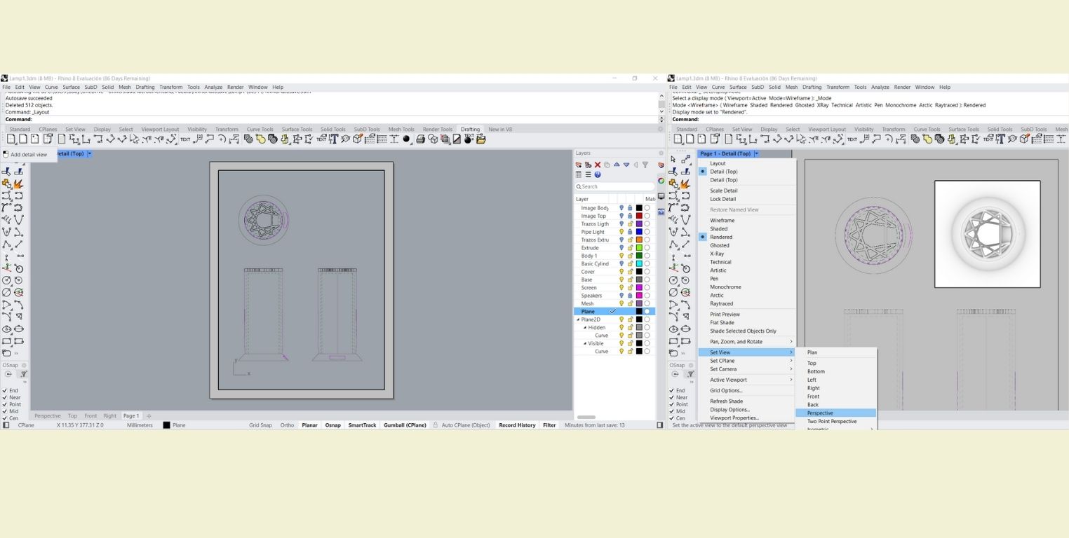
To replace the perspective I deleted I added a view in "Add detail view" and also changed the default view to one where my model was displayed with materials.
-
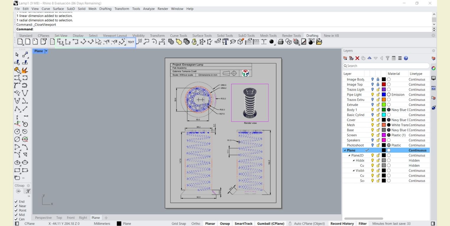
The last thing was to add text details and measurements with the marked tools.
Rhinoceros Verdict
Visually it is possible that the interface could be improved. At first having all the visibility of the tools could be somewhat frustrating for someone who is just their first interaction with a 3D modeling program. But balancing the scales, at the top once you select a tool, the program guides you step by step to use that tool, something that I find quite positive.
To rectify things it is very difficult to go back steps without having to do it all over again, or repeat steps, because unless you use Grasshopper you can't do parametric designs in Rhino. On the other hand, the program allows you to work in layers, and this can improve the situation, however, you must be attentive to separate the drawings from the extrusions in different layers, etc. If you are not attentive everything can remain in one layer and it is not really that bad, but the differentiation with colors helps a lot in the process.
One good thing is that it allows you to make organic shapes very easily, as well as work with hollow surfaces from the start and then convert it to solid if desired.
LET’S TRY TO DO THE ABOVE WITH SOLIDWORKS
 SolidWorks
is a CAD software that allows you to model parts mechanically in 2D and 3D in a way that allows you
to create assemblies and extract from them technical drawings with the necessary information for
production.
SolidWorks
is a CAD software that allows you to model parts mechanically in 2D and 3D in a way that allows you
to create assemblies and extract from them technical drawings with the necessary information for
production.
According to my experience with Solid, it is very easy as long as you have the measurements of what you are going to model. Something bad for me because with my previous practice I realized that I was missing the measurements of the enneagram figure, so to make everything more or less in proportion I decided to do it based on a photo.
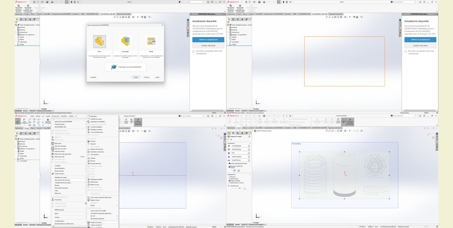
- So I started by opening the document of a new part and in the elevation plane with the "sketch tool " I inserted a " Sketch image ". In this step I wanted to dimension a specific part of the picture, but I could only do it in a general way. (Maybe in this step my memories to use SolidWorks started to die).
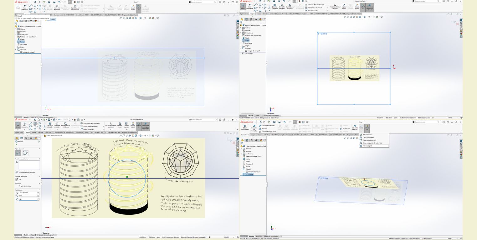
- Then in the " Plan " drawing I started a new sketch to make the spiral base of the lamp, so I drew a circle and the diameter I put a value of 90 mm.
- I finished the sketch and having selected the circle in " Curves " I clicked on " Helix and spiral ".
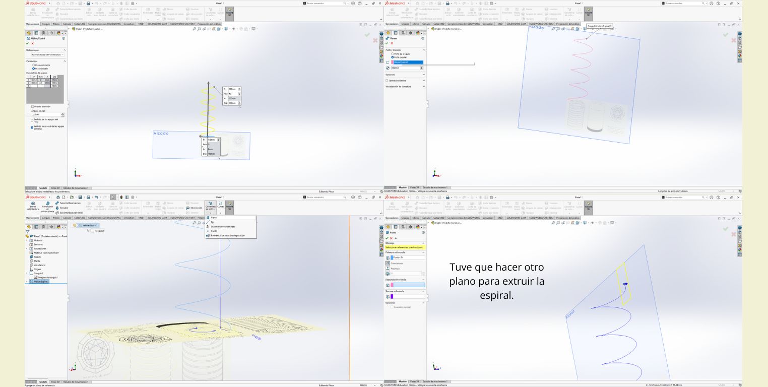
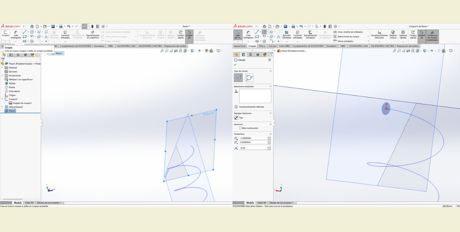
- The next thing I did was to give it a height (140 mm) and a number of revolutions (4.5). This is the base of the drawing, to give it volume I had to make a plane in one of the vertices of the spiral.
- Then on the plan just made, I drew a circle in the center of the vertex of the spiral and gave it a diameter of 15 mm before finishing the sketch.
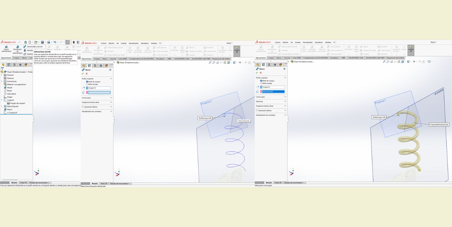
- Then I selected the circle and in operations I applied "Overhang/ Base sweep" and as a reference I selected the spiral. Once done I got the way the light will go up in the lamp, however, I realized that I did many more steps compared to Rhino.
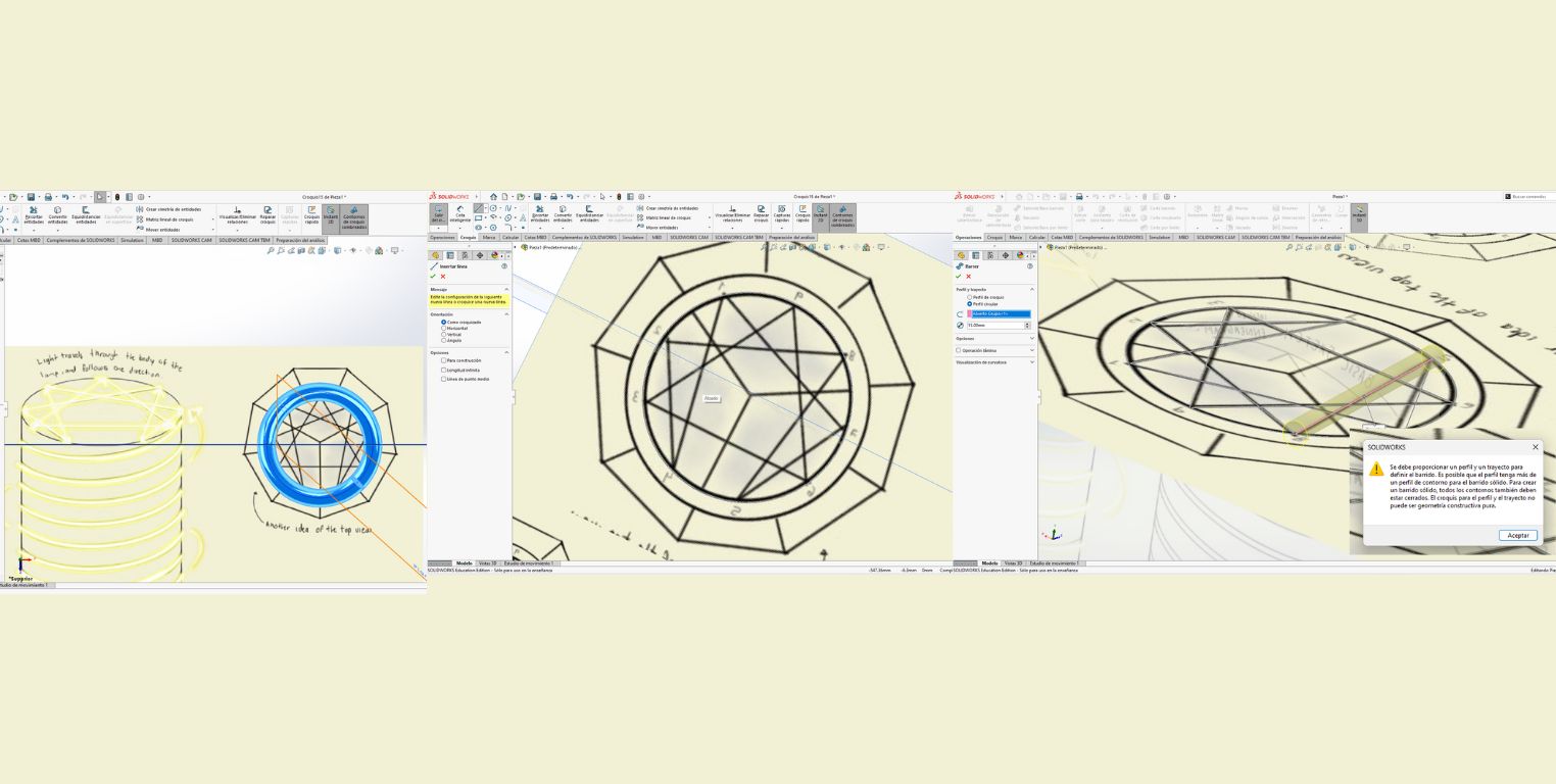
- I made a sketch again in the "Plan" plane to draw the representative figure of the enneagram. For that I had to hide the spiral, because it did not let me see the picture correctly, the bad thing about this is that the lines were not visible to adjust my drawing correctly. I continued then drawing the figure with the "Line" tool.
- When I finished I wanted to apply the "Overhang/Swept Base" tool, but I could only do it in one direction, because I got a warning that said that a swept surface could not be a constructive geometry. Points off for Solid. I thought, yes it could be done, however, now I am happy I chose Rhino as my primary software for this installment.
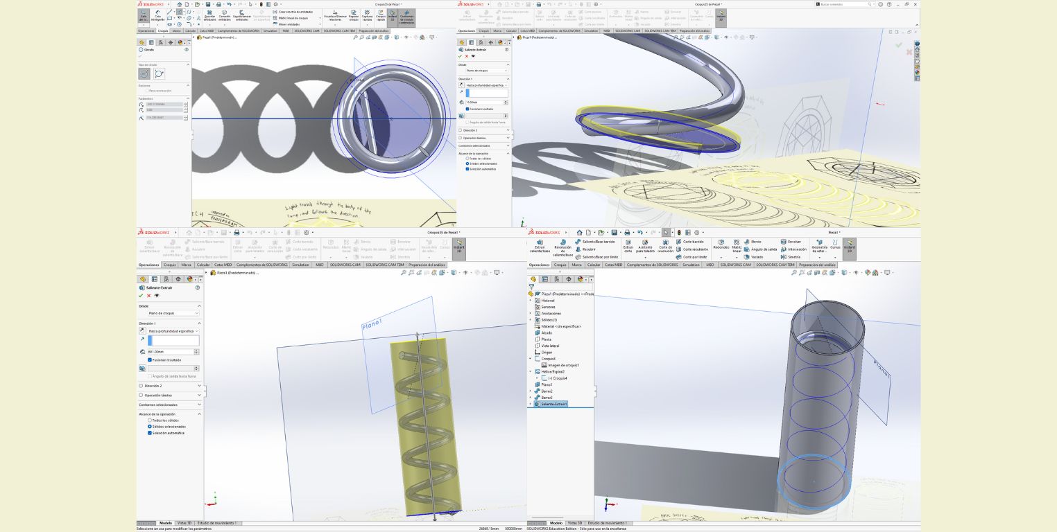
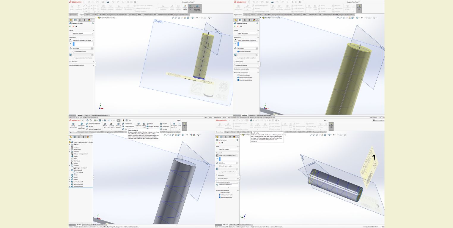
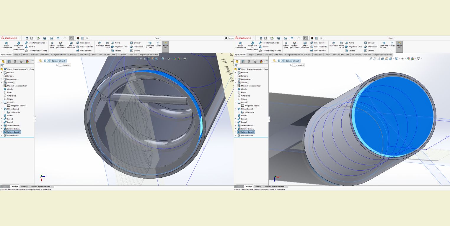
- I then proceeded with the outer body of the lamp, and for this I drew two circles on the "Plan" plane, and then extruded the difference between the two circles. This went relatively well until I could not close the top part. Here I started to think that maybe the problem was not Solid but me.
- Hoping to solve my previous problem I decided to extrude both circles separately, and then make a cut with both. Then I extruded the larger circle in the normal way, and the second circle, the smaller one I extruded as a cut.
- This is not a step, it is rather just to show how what I did in the previous step did not work either, because what I got were two solids with a space between them, and I did not know how to continue at the time.
This is as far as I got in SolidWorks, I haven't used it for a while (about a year) and I didn't think it would be so difficult to use it again. Especially, because I remembered it very friendly and even somewhat intuitive. But sadly the lack of practice can be noticed. Especially, because now that I was documenting I could see that the "Empty" tool could have helped me a lot more, and maybe steps 10 and 11 would not be what they are today. I leave the file in the "File" area anyway.
SolidWorks Verdict
It has a very user friendly interface. It is really not difficult to start working on it, I remember that when I started using it was after learning a bit of Inventor and comparing the interface it seems to me that they can be somewhat similar. One good thing about Solid is that on the left side you can see the progress of the steps done, and this allows you to easily go back to modify the size of a figure or drawing. This is relevant because Solid also allows you to make parametric designs, which means that the changes can be more controlled, so that when you change a variable, everything that is tied to that variable changes and adapts to it.
LEARNING FUSION 360 !
As a personal challenge I decided to use Fusion 360 to learn how to use this program. It reminds me a little bit of Maya because it allows you to deform solids very easily (even more than Maya). And for this occasion I wanted to try to make a parametric figure, as we were told that this is what next week's assigment will be about, so I wanted some practice too.
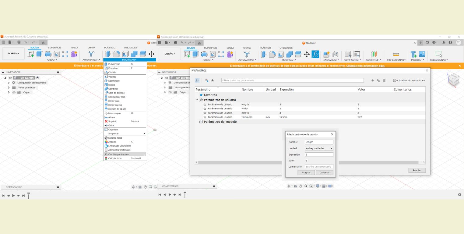
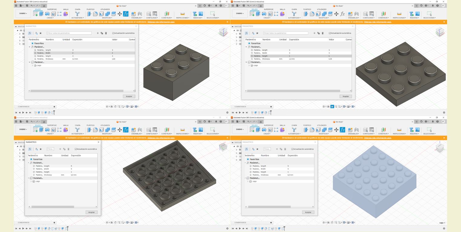
What I did was to follow a tutorial to make a lego. So in Fusion 360 with a new file I added the parameters I needed. According to the video it was best to add the parameters needed, before anything else. In this case it was just width, length, height and the thickness, each of them were given a value according to a reference image used in the video.
In the video it is mentioned that it is best to work with components, as these are worked from solid bodies. Once I was sure of this I proceeded to start a sketch on a flat face.
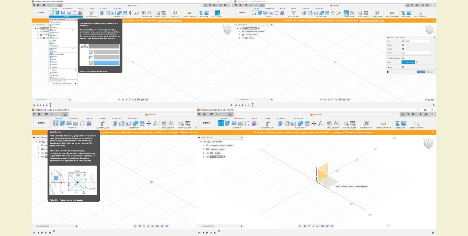
Making a lego is really not that complicated because it consists of a rectangular prism and cylinders. So in theory it could be made with solids directly and save us the step of drawing a rectangle and then extruding it. But I followed the tutorial anyway and what was done was to draw a rectangle with any measurements at first.
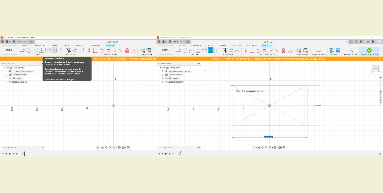
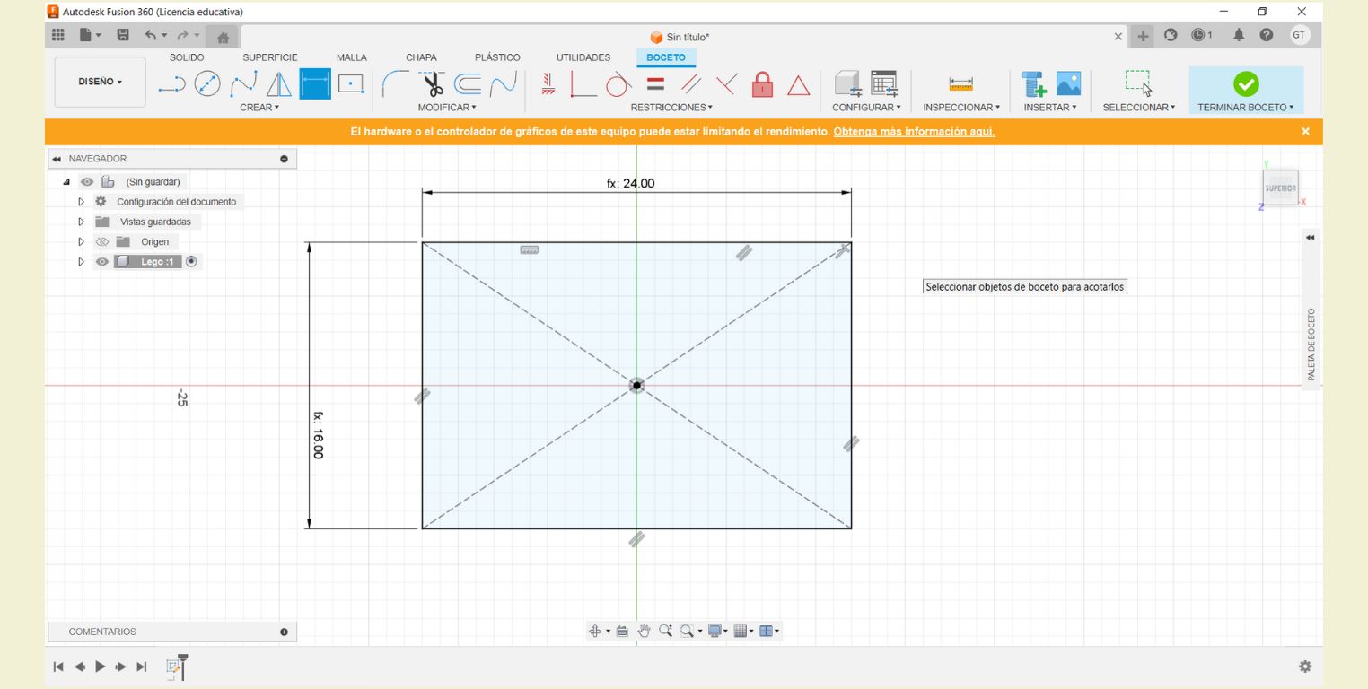
The parametric starts once you use the sketch dimension to make a reference and then indicate that instead of a specific distance that is the "Width". In the video "Width" was multiplied by "8", so you can not only enter the parameters, but also operations with the parameters, something that I find quite attractive to work with.
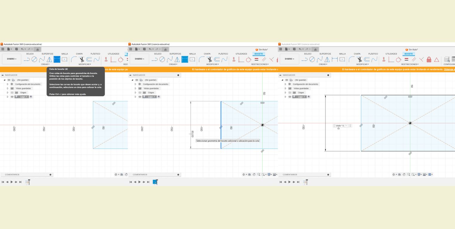
When you click outside the parameter, the operation (if any) is displayed. It is very user-friendly because you can also rectify the measurements easily and quickly. I think it is somewhat similar to SolidWorks. And the next thing was to finish the sketch.
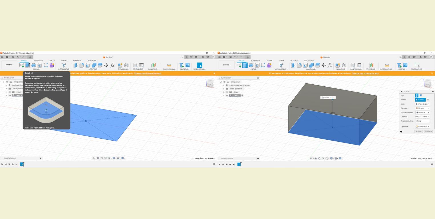
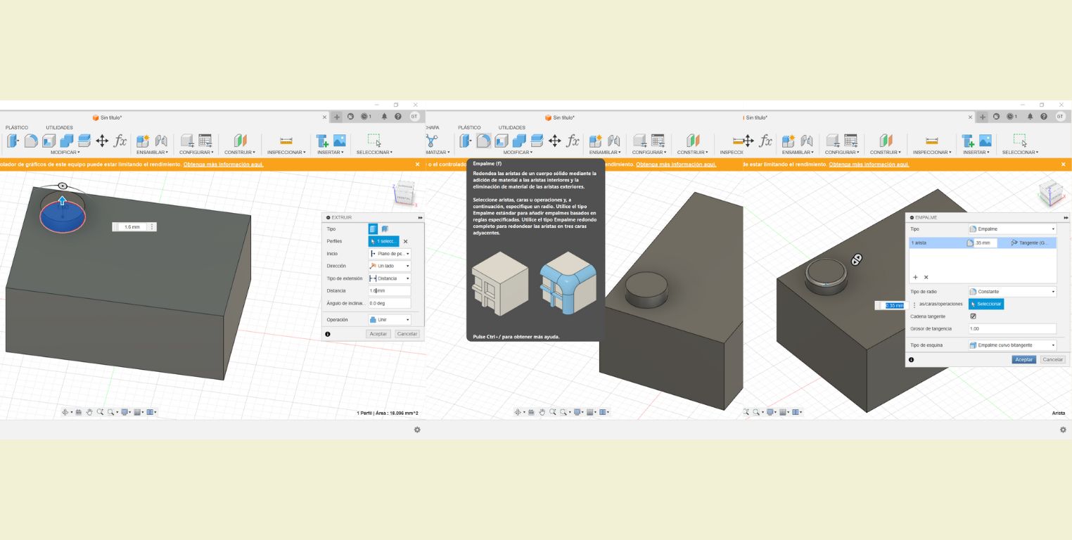
The next step was to extrude the drawn rectangle. It is only necessary to specify the surface to extrude and on the right side a window appears where the parameters can be configured. In this case in "Distance" we set "Height*3.2".
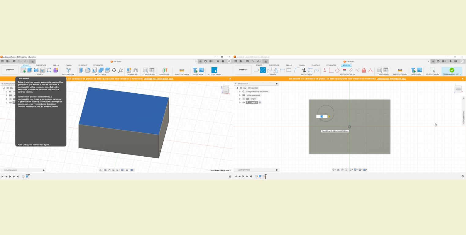
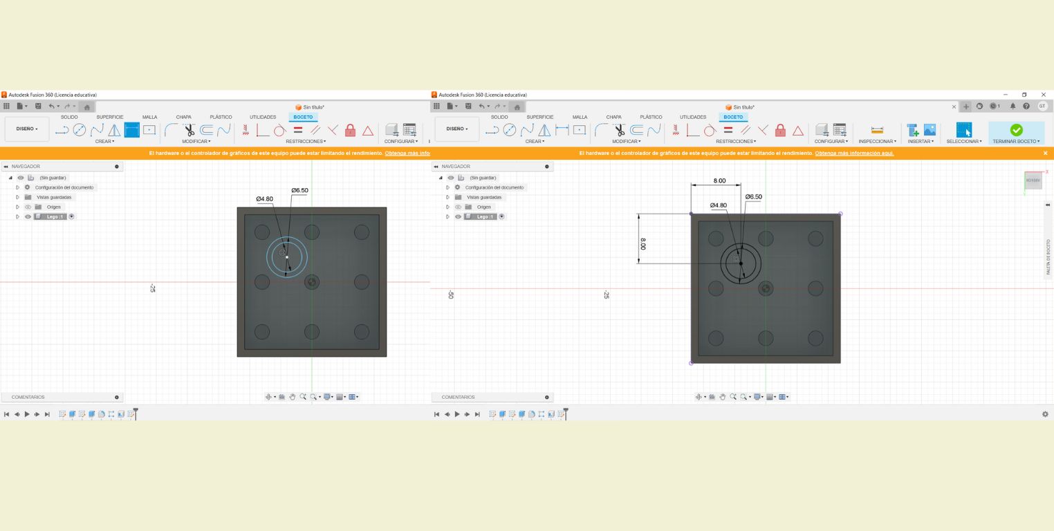
Once extruded. On the upper face I started a new drawing and made a circle with a diameter of 4.8, although you could also add the parameter "Diameter" to make it parametric.
Then with the "Sketch dimension" tool I positioned the drawing of the circle creating distance references, from the center point to the ends. I gave these references a value of 4.
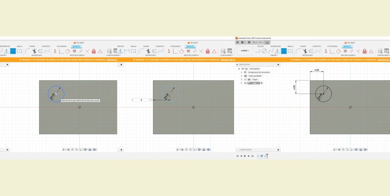
I finished the sketch of the circle and extruded it 1.6 mm, the following was not done in the tutorial, but with the "Splice" tool I wanted to round a little the edge of the last extrusion. It was really something very smooth, I gave it a value of 0.35 mm.
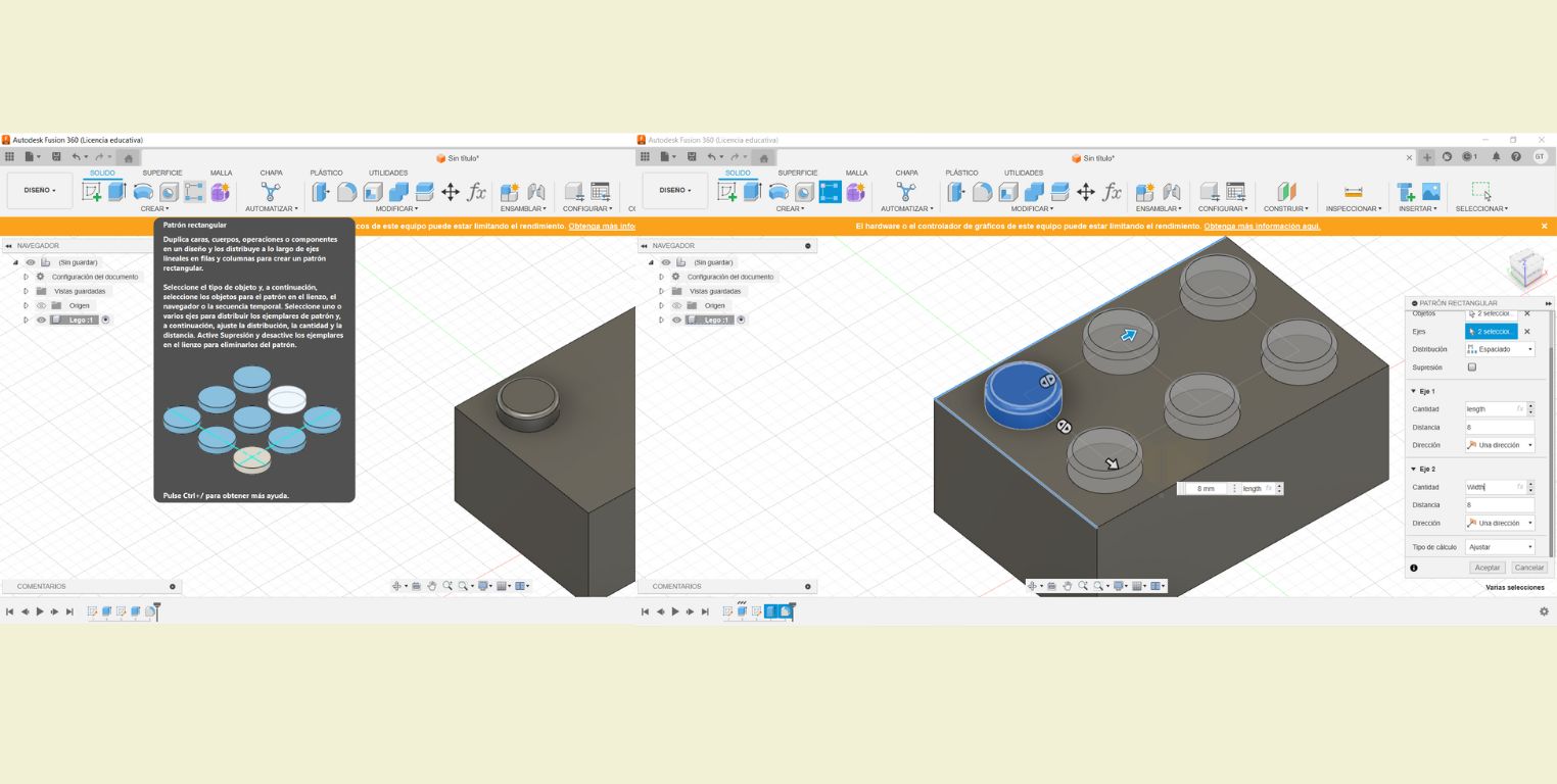
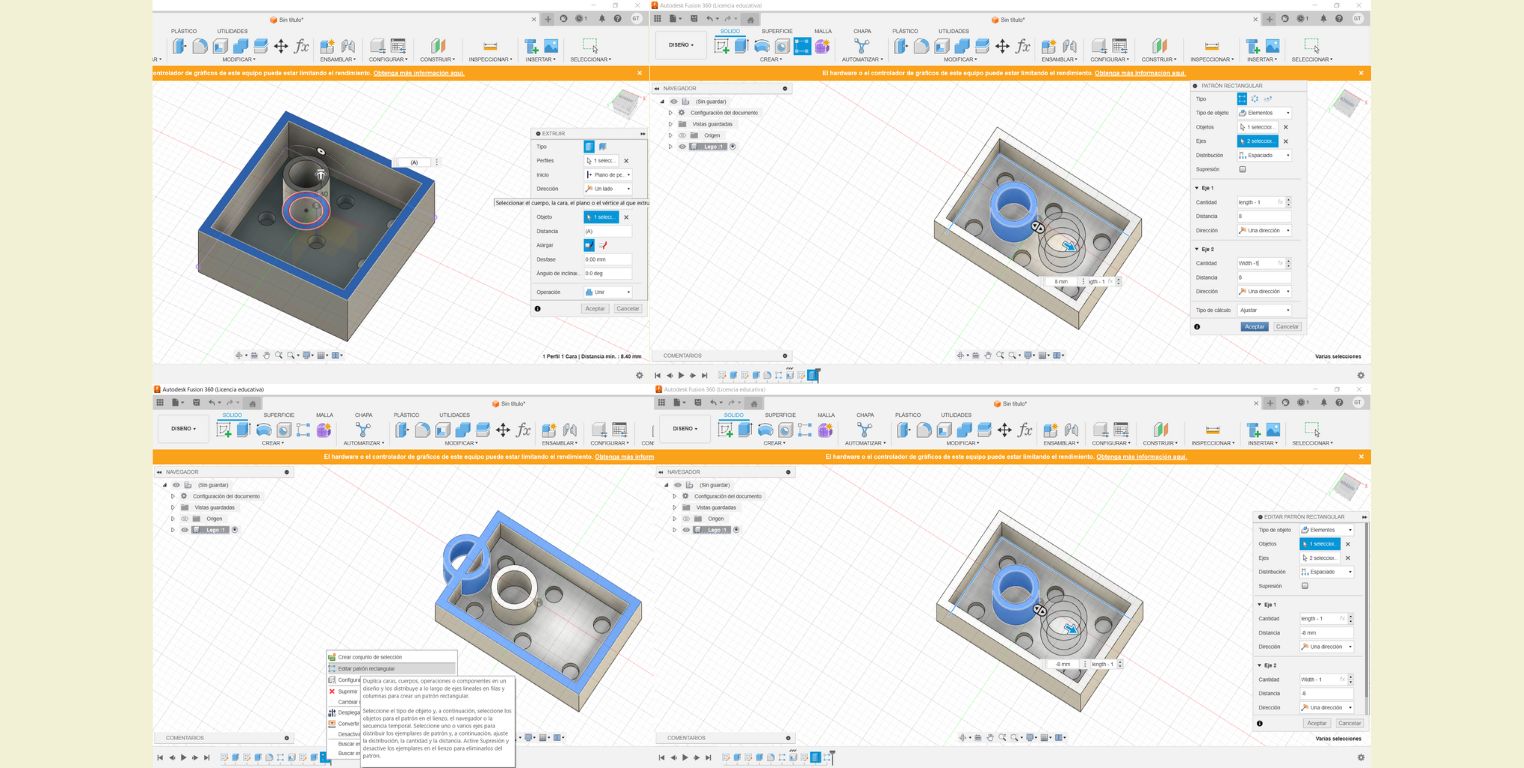
The next step is where it takes the shape of a lego, because a rectangular pattern was used on the last extrusion and the splice that was made. For this at the bottom I had to select the extrusion and the splice separately, as this is how the progress line marks it. Then in the pattern setup it was specified that the "Amount" in Axis 1 would be represented by "Length" and in Axis 2 by "Width", while both axes would maintain a distance of 8.
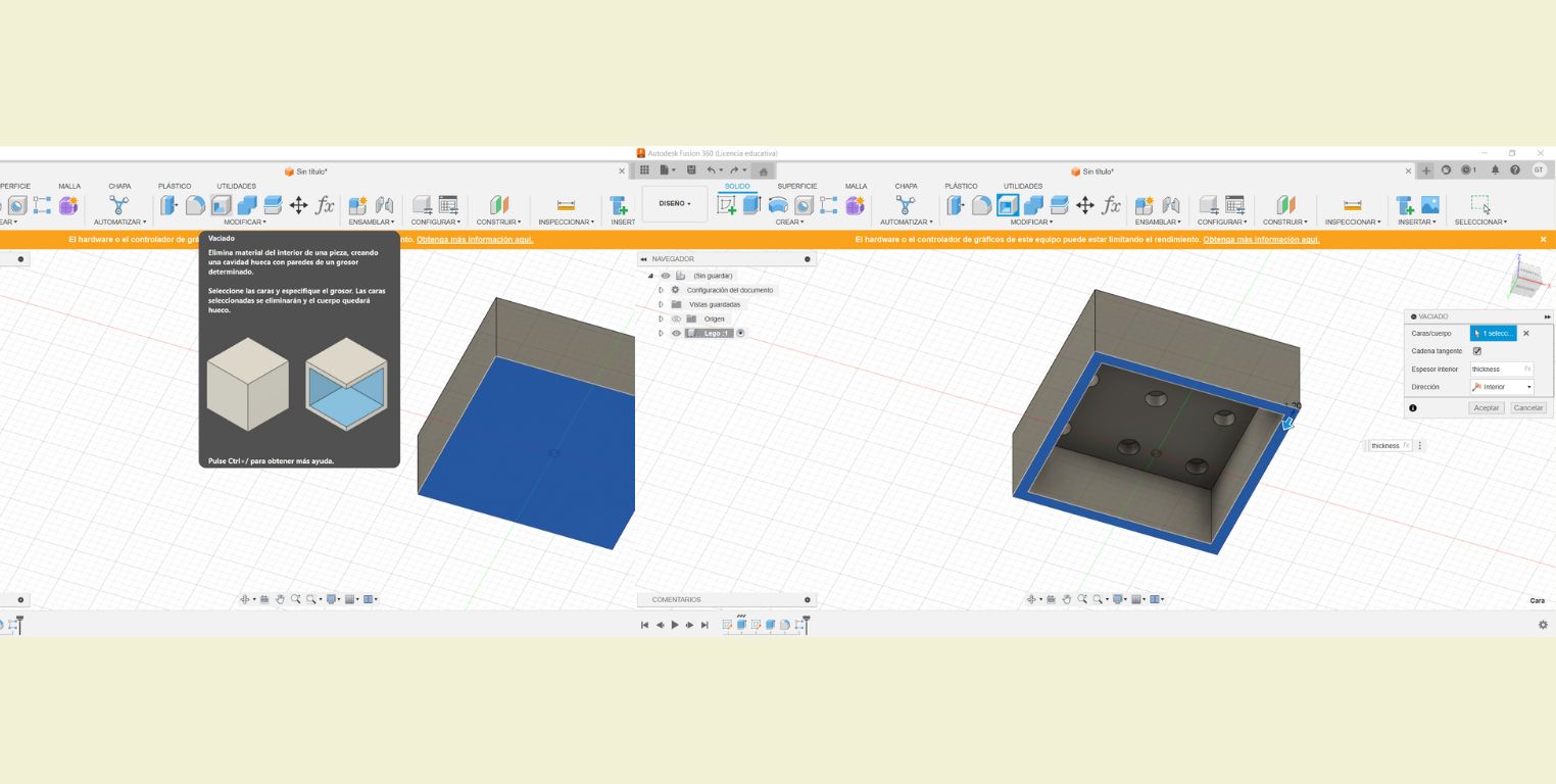
Then a little rectangular body and I selected the bottom face to apply a "Cast" to it, and in its configuration I indicated that the "Inner Thickness" would be "Thickness".
In the new bottom face of the figure I made the sketch of two circles, one inside the other. With radio of 4.8 and 6.5 mm. At the same time I made an end distance reference of 8.
I extruded the previous drawing and in "Distance" I selected the surface of the internal thickness to indicate that the extrusion had to go that far. Then I made a rectangular pattern again and in the configuration of both Axis 1 and 2 I subtracted length and width - 1. According to the preview it was correct. But when I hit accept the pattern was made in a wrong direction. So in the progress line I right clicked to edit the above pattern in "Distance" instead of it being 8 positive, I gave it the setting of "- 8".
The next thing was to verify that changing the parameter values changed the figure, and it did. It really wasn't that difficult. And it seems to me that the program happens to be a combination of Solid and Rhino, so it was easy to associate the tools.
Fusion 360 Verdict
It's a very user-friendly platform and easy to understand if you've already had contact with other modeling programs, but otherwise I also find it intuitive. Besides each tool gives you an explanation of what it does or what it is for. It allows you to go back in the progress line and easily edit each step. This is actually a great advantage. You also have the option to develop parametric models, which makes editing them even easier.
2D DRAWING
For the 2D drawing I used the Illustrator program.
 Illustrator
is a vector graphics software, which allows that no matter the format or print size, the image
remains faithful to
the original design without pixelation.
Illustrator
is a vector graphics software, which allows that no matter the format or print size, the image
remains faithful to
the original design without pixelation.
I really like cats, they are my favorite animal. And on the other hand a hobby that I love because it has accompanied me in my growth is reading. So I decided to draw the image of a kitten and books.
Join me to see the step by step!
-
I started by opening a new artboard with vertical orientation.
-
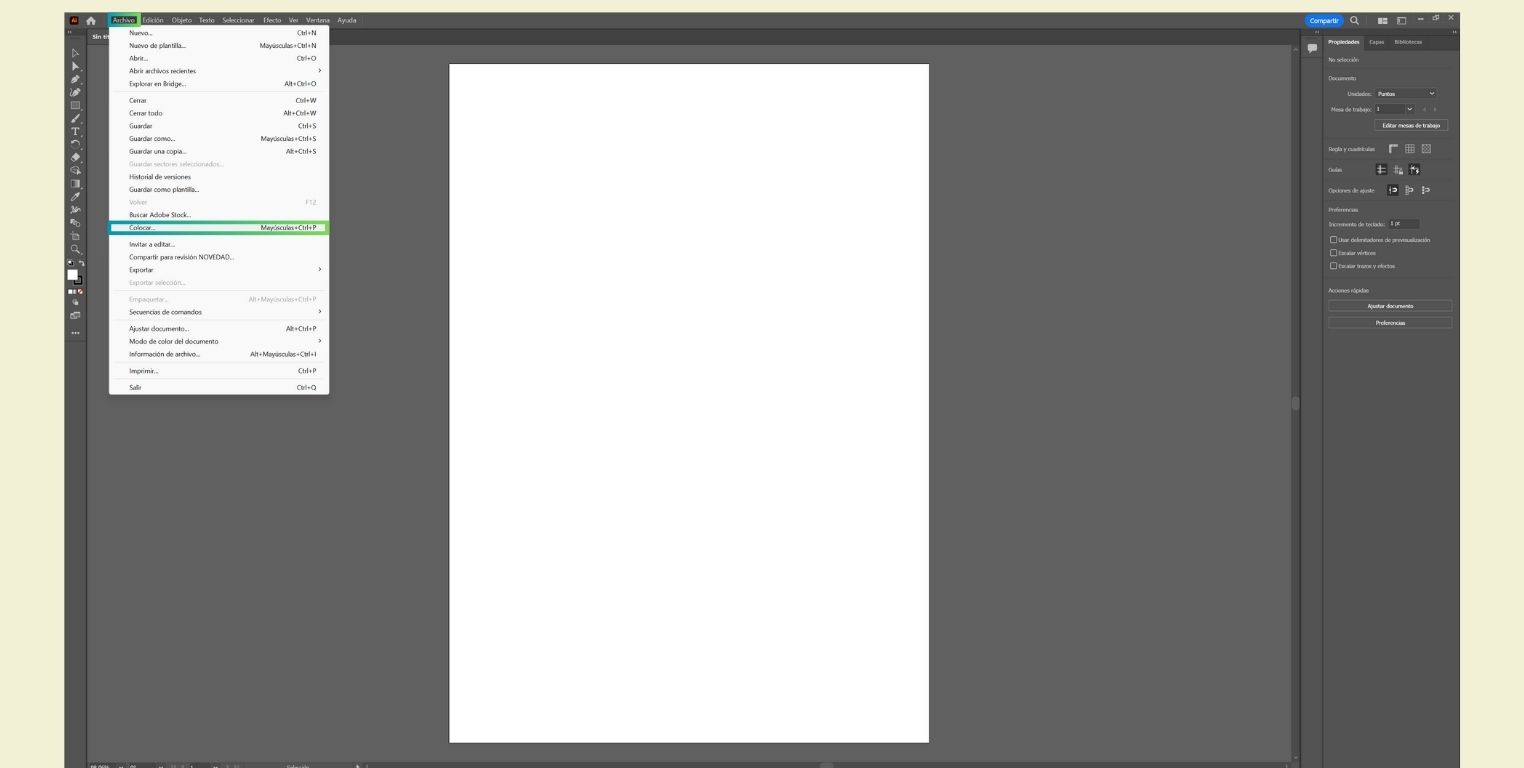
Then in the "File" menu I selected the "Place" option to add an image. In this case I chose one from Pinterest which you can findhere.
-
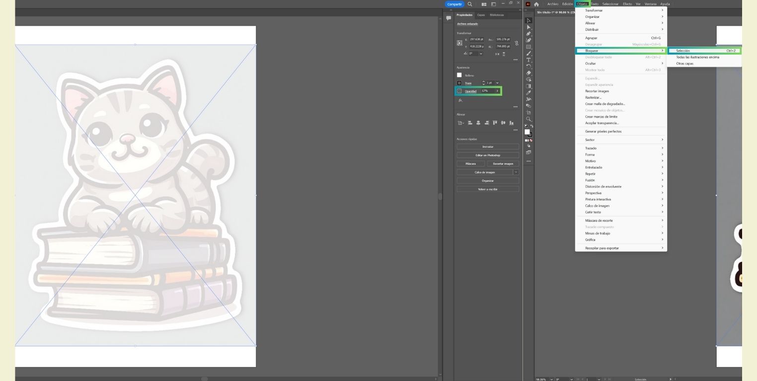
To be able to draw over the image I lowered the opacity a bit and to avoid moving the image while copying it, I locked it by selecting it and going to the "b>Object" menu to do so.
-
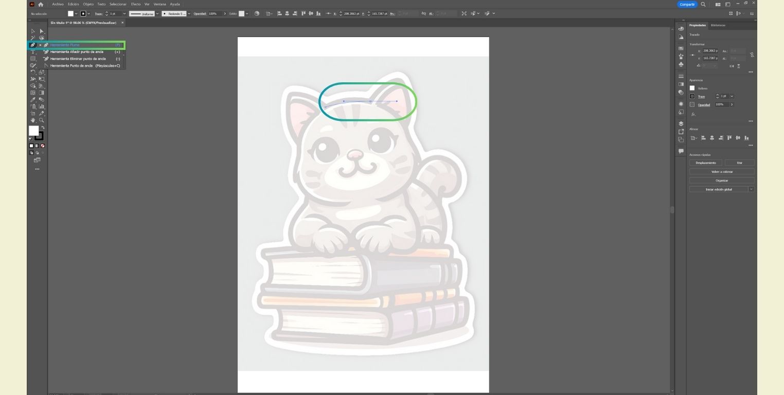
I started to draw with the help of the "Pen" tool that allows to draw connected lines and curves.
-
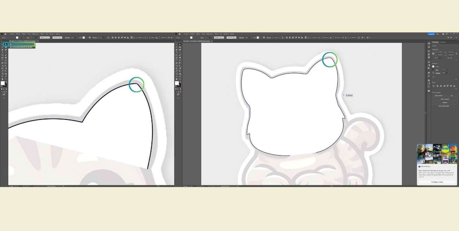
After making the first strokes I modified them a little to make them look smoother. For that I used the "Direct Selection" tool that allows to select and drag the anchor points to make modifications.
-
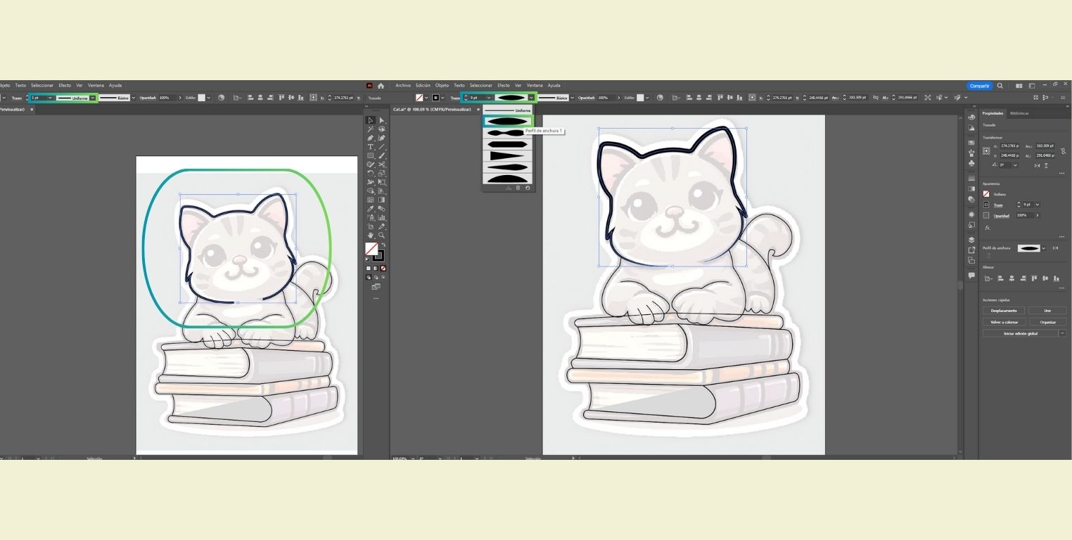
I continued modifying the line I drew, but now changing the thickness of the line by increasing the points (pt) and also adding a shape to the stroke I made. This way you can obtain different types of lines.
-
Until now I had drawn with "Pen Tool" so that everything was connected, however, the divisions of the toes of the paws I made them as separate lines. So I duplicated them with "Ctrl c and Ctrl v" and right clicked to "Transform" the lines and applied the "Reflect" tool to reflect them at 90°.
-
For the part of the face I used the "Ellipse" tool to draw the round and oval parts easily.
-
To add color to the drawing I pasted the reference photo to one side. And when selecting one of the strokes I also selected "Eyedropper" to copy the exact color of the original drawing.
-
For the last details I used the "Paintbrush" tool to apply freehand brushstrokes. The following picture is a reference of the tool, but you can see it applied in the picture below.
-
Finally, I right clicked to unlock the background photo and delete it to keep the drawing I made.


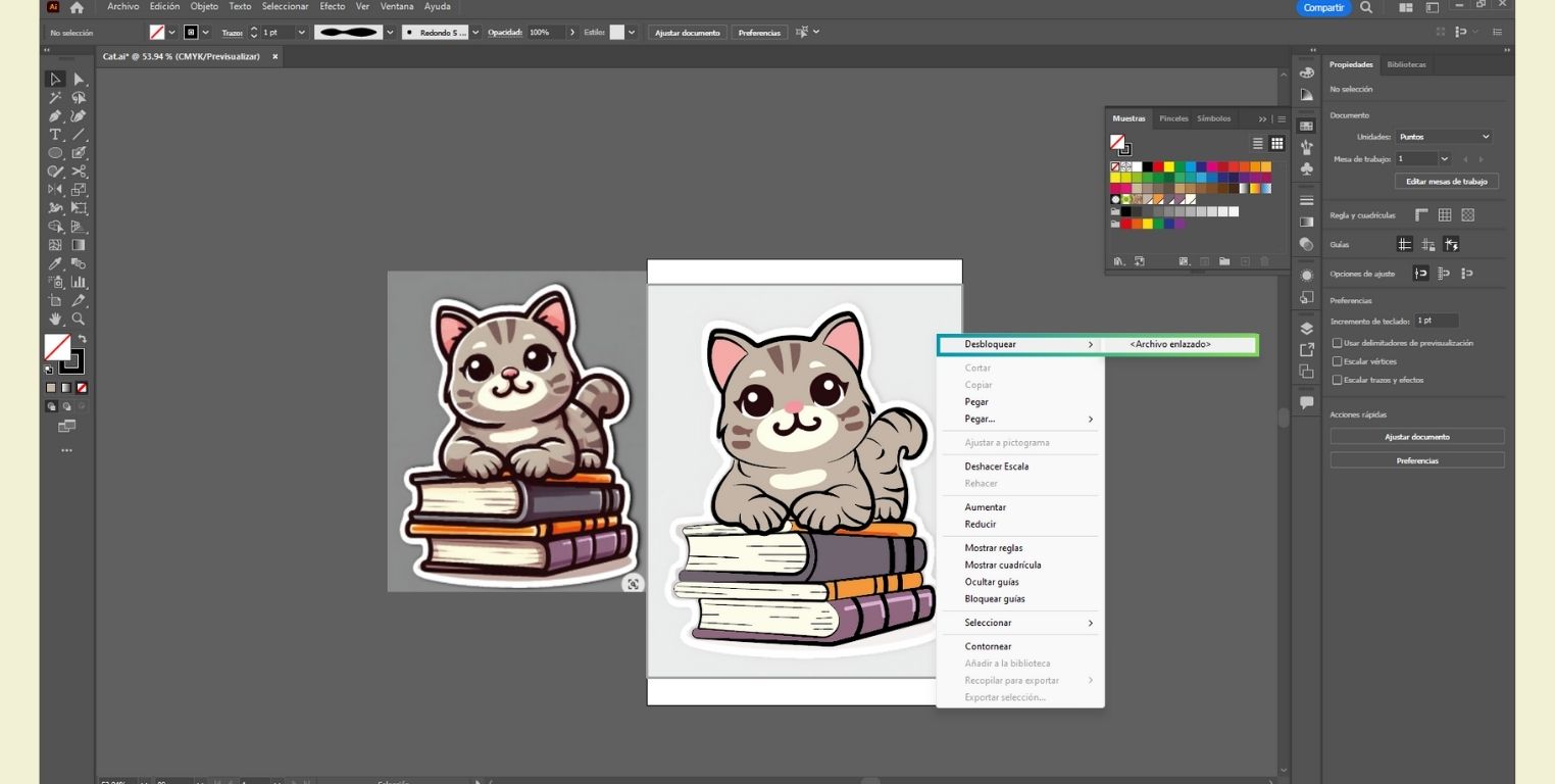
Here I show you the final result. You can find the file in the "File" area.

Conclusion
Despite having experience with two of the evaluated programs it was a bit complicated to go back to using them after a while, plus in the case of 3D modeling, I had never worked on a model without measurements before; and although it was not so complicated it was a trial and error work before getting everything right. That's why we must not forget that in order to learn you have to make mistakes.
In the case of Rhinoceros, which I used as the main software for the modeling of my final project, it helped me a lot the "Command" bar that was guiding me step by step, this is a particularity of the program that I like a lot, because if you don't know how to use a tool or you are new to the program it guides you. And finally I think I would like to try more shapes with the base I already made. For now I think it was a good result and also thanks to the drawing of the plan I made I already have the general measures to work on my project.
In the case of SolidWorks, I think it is an excellent program to work especially in a more formal way, as it is one of the most used for production and industry. However, I could notice that in some cases I did more steps than I did in Rhino to reach the same result. But I do not want to leave everything in the program, I recognize that the one who uses the program also has responsibility and I still have the experience to explore more tools and continue practicing it so as not to forget it.
In the case of Fusion 360, I really liked that being the new program that I started to learn it was very friendly, I really appreciate that it was easy to use and understand. It is true that surely because of the familiarity with other 3D modeling programs it could have been easier for me, but for the same reason I think it can even be easier to use than other programs, I would say that it has a resemblance to SolidWorks because of the progress line and the possibility of working parametrically, but it is less complicated to use than SolidWorks.
When it comes to 2D drawing in Illustrator I really enjoyed working with the line and polyline tools again. Although they are basic tools, the truth is that they can provide great results if you know how to take advantage of them. At the beginning I think you may need a tutorial to start using Illustrator, but after the basics you can explore the program without problems, for example, one of its peculiarities is that you can work in layers, but in my experience I learned that even without the layers it is not so complicated to use, so I would say that there are also levels in which you decide to use the program, but you can always get more out of it.