To begin with, this was the assignment that finally made me realize how difficult FabAcademy is. For someone who is completely new to some of these topics I found this one to be absolutely difficult. I have never cut or designed any piece for cutting ever in my life until this very moment.
However, after accomplishing this week, I have felt that I have reached a different level with CAD software and as a new person. Thank you Neil.
Lasercutter
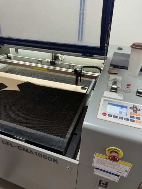
At Puebla's FabLab, we're equipped with three laser cutting machines, including the CAMFive Laser Cutting Recorder CFL-CMA1080K. This machine features a 1.00 x 0.80m working area and offers automatic height adjustment of the table. It also comes with a rotary attachment, allowing for the engraving of cylindrical items.
.png)
Below is a list of materials that can be cut and engraved with this machine:
| Soft materials | Cut | Graven |
|---|---|---|
| Paper | ✔ | ✔ |
| Paperboard | ✔ | ✔ |
| Foaming | ✔ | ✔ |
| Felt | ✔ | ✔ |
| Cotton fiber and mixed fabrics | ✔ | ✔ |
| Thick synthetic fibers fabrics | ✔ | ✔ |
| Synthetic fabric Lycra and thin | ✔ | 𝙓 |
| Leather (Natural leather) | ✔ | ✔ |
| Leather (Synthetic leather) | ✔ | ✔ |
| Rubber | ✔ | ✔ |
| Cork | ✔ | ✔ |
| Hard materials | Cut | Graven |
|---|---|---|
| MDF | ✔ | ✔ |
| Wood | ✔ | ✔ |
| Foaming | ✔ | ✔ |
| Triplay | ✔ | ✔ |
| Plastic | ✔ | ✔ |
| Acrylic | ✔ | ✔ |
| Glasses and crystals | 𝙓 | ✔ |
| Ceramics | 𝙓 | ✔ |
| Marble, Onyx and other rocks | 𝙓 | ✔ |
| Tile | 𝙓 | ✔ |
| Metal (apply special resin) | 𝙓 | ✔ |
The machine's specifications are as follows: it weighs 185 Kg (407.85 pounds) and has dimensions of 1.35 meters (53.15 inches) in width, 1.17 meters (46.06 inches) in height, and 0.99 meters (38.97 inches) in depth.
Upon introducing us to the laser cutter, we were instructed on its operation, emphasizing adherence to safety protocols. The initial steps involve ensuring the device is plugged in, then turning on the power via the voltage regulator switch, set to input 216V and output 220V.
Activating the machine involves disengaging the emergency stop, using the key, adjusting the intensity dial, and pressing the laser button, which lights up white to indicate activation. Caution is paramount as the laser beam is invisible. The machine should now be looking something like this:
For cutting or engraving, you can upload a design directly via USB or use dedicated software, which requires files in .DXF format.
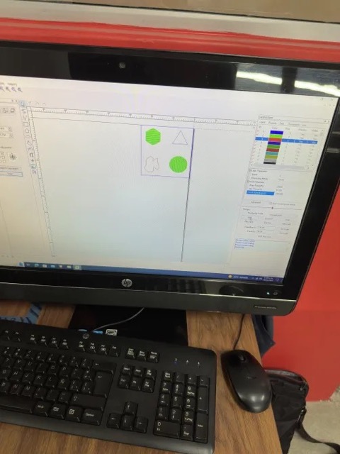
After launching the software (SmartCarve), we import our design, choosing the measurement unit (in our case, millimeters). The software, though simple, includes essential features for adjusting settings or creating designs with basic shapes. It displays the laser's intensity range and speed settings, crucial for the process.
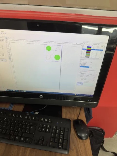
It's possible to set multiple layers with distinct settings, beneficial for separating cutting and engraving tasks, with engraving always preceding cutting by adjusting priorities in the software.
Once the design and settings are finalized, hitting the Start button sends the job to the cutter for execution.
It's important to adjust the laser tip's height to between 5mm and 6mm above the material, positioned on the cutter's base. Our tests were conducted on 3mm MDF.
Test
After characterizing the cutter as a Group Assignment , we experimented with creating various figures using distinct layers and configurations to explore the laser cutter's capabilities.
This involved assigning specific settings to each layer, tailoring them for either cutting or engraving to optimize the process.
Here's a breakdown of how we conducted our tests:
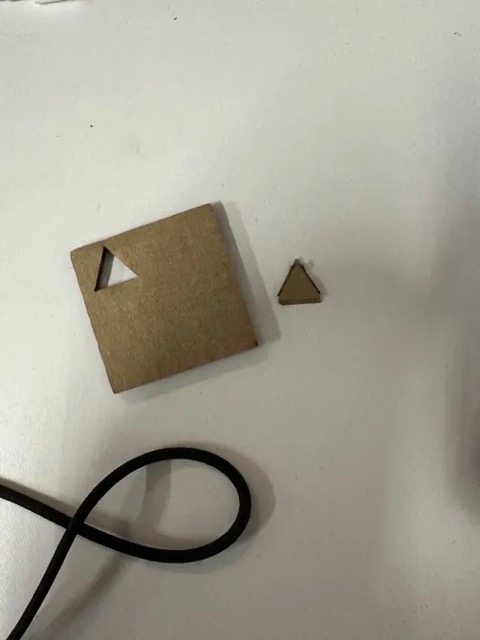
Multi-layered Geometric Shapes
- Objective: To create a piece featuring a combination of geometric shapes, where each shape has a different depth or texture.
- Procedure: We designed a file containing circles, squares, and triangles. For each shape, we assigned a different layer:
- Circle: Engraving layer with low intensity and high speed for light surface marking.
- Random shape: Engraving layer with medium intensity and medium speed for deeper marks.
- Triangles: Cutting layer with high intensity and slow speed to cut through the material.
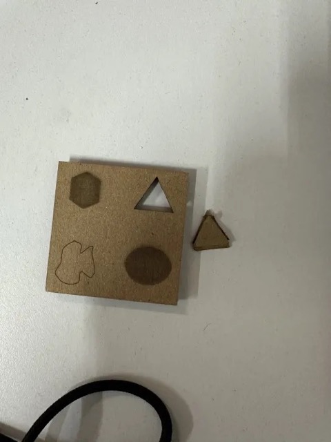
- Material: 3mm MDF.
- Outcome: Successfully created a piece with varied textures and depths, demonstrating the laser's ability to handle multiple configurations in a single job.
Press-fit construction kit
Embarking on the creation of a construction kit with Fusion 360 presented a journey filled with both challenges and insights, which significantly influenced the direction and outcomes of the project.
Not only was it my first time actually designing something that was going to be made physically, but also it was my first using a laser-cutter for the first time in my life.
The failed practice: Laptop Stand
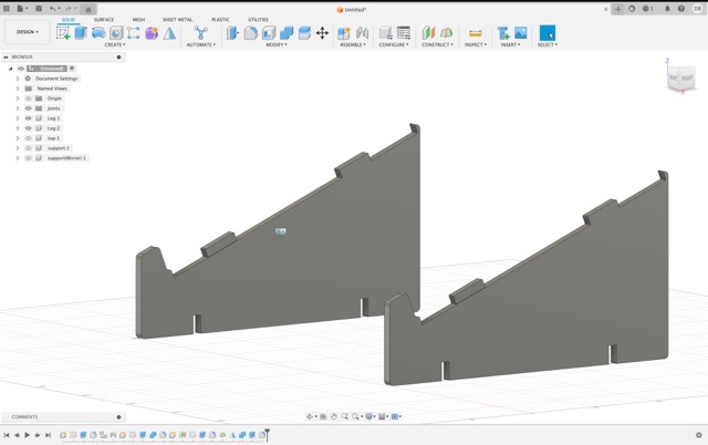
This endeavor began with an ambitious attempt to design a laptop stand that not only served a functional purpose but also exemplified the principles of parametric design and press-fit connections.
The goal was to engineer a stand that was adjustable and easy to assemble, showcasing the potential for precision and flexibility within digital fabrication.
This attempt to design a laptop stand was based on the tutorial from Dylan T.
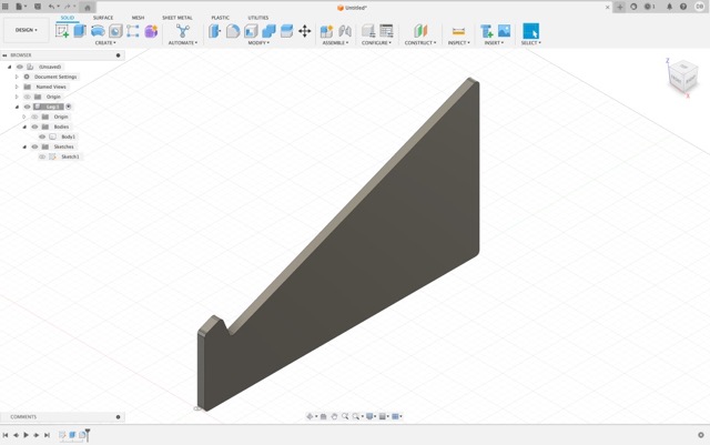
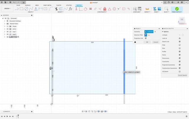
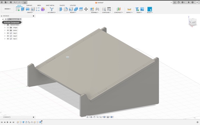
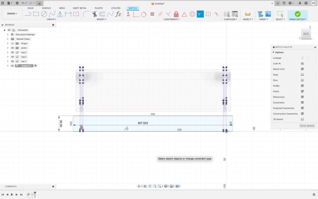
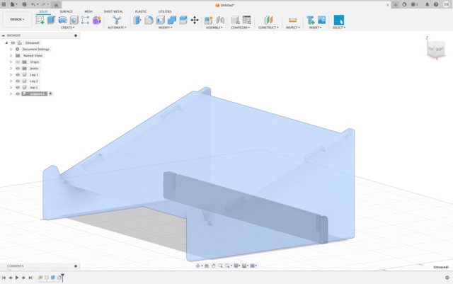
To begin designing this Laptop Stand I needed to start a new Fusion 360 project.
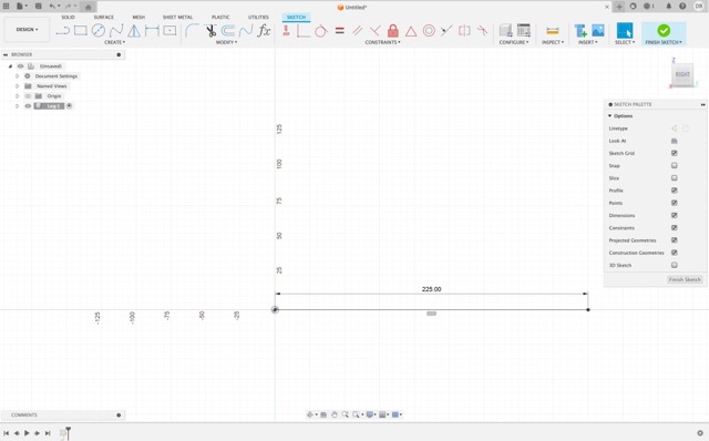
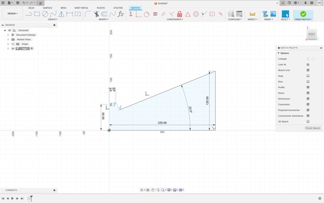
From there, create a sketch and assign the measurements of the base of the stand.
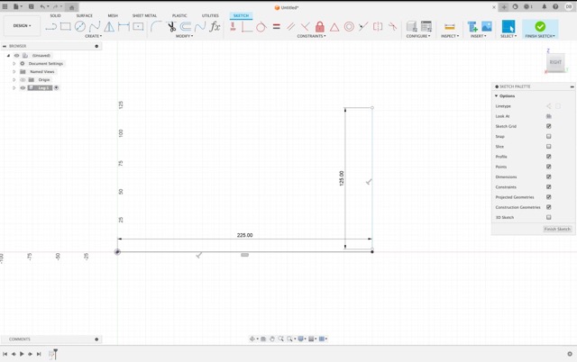
Next, generate the measurements of the height of the stand.
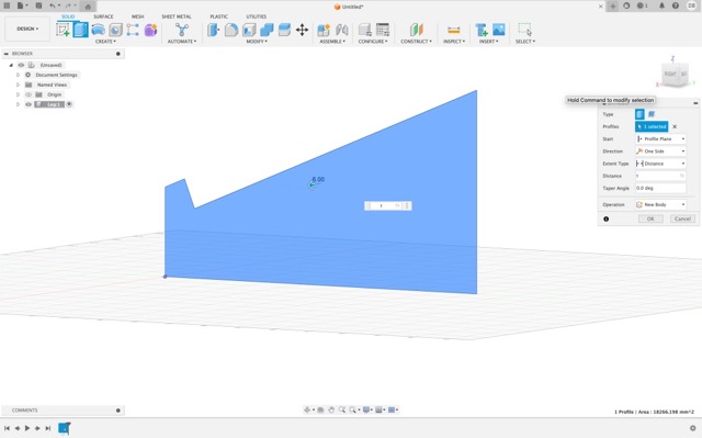
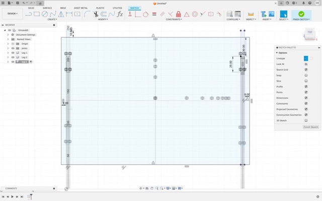
With those measurements in place, generate a figure that resembles the stand. Then, adjust that figure so that the parts that will hold the tablet together are at the bottom.
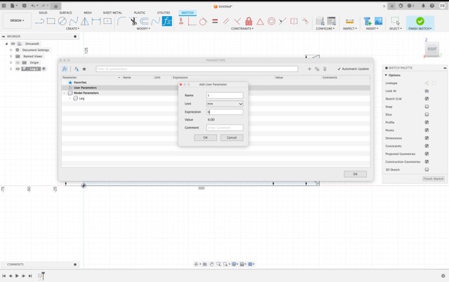
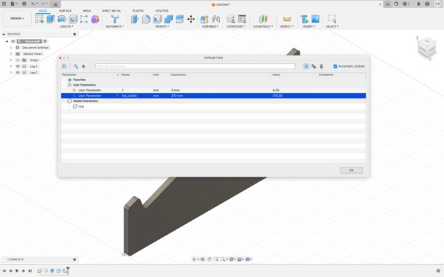
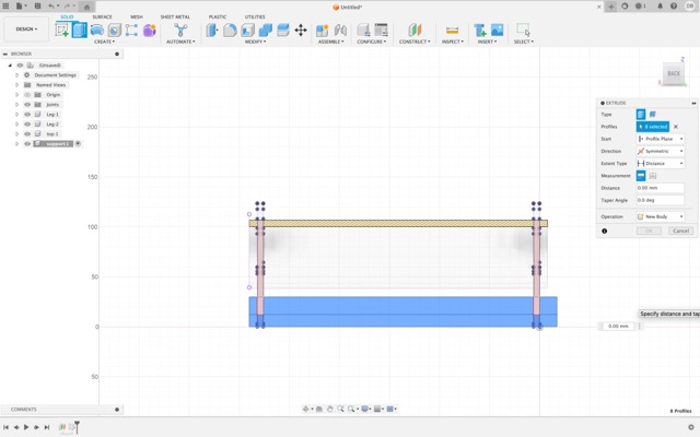
Next, create a new parameter that will be the one that will hold the value of how much extrude we want for the legs of the stand.
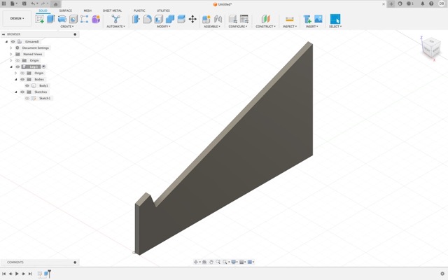
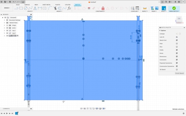
Next, round the edges so that way it will all assemble better.
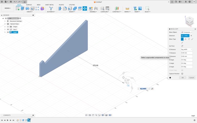
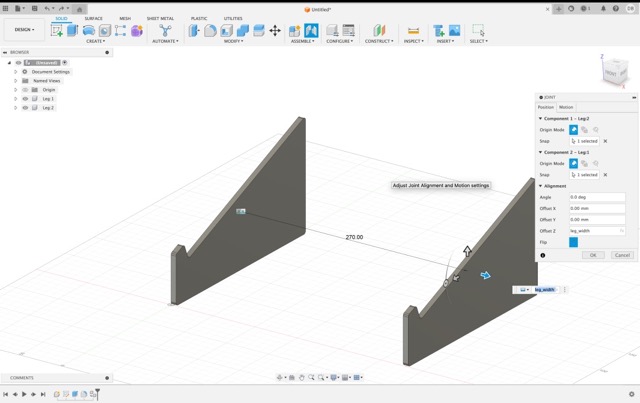
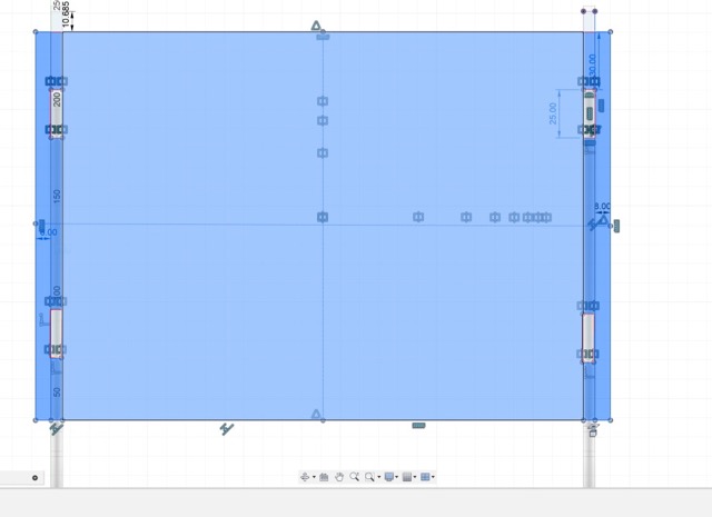
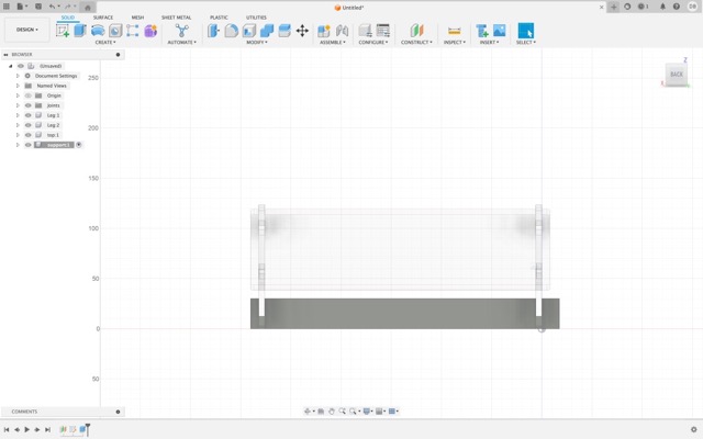
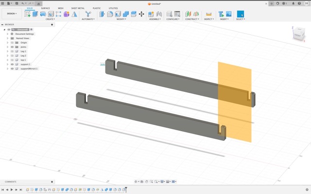
After verifying that the legs are correct. Create a new parameter called "leg_width" and copy the leg. Set the distance to "leg_width" so when it needs modifiying you won't need to change everything again. This is what defines a parametric design.
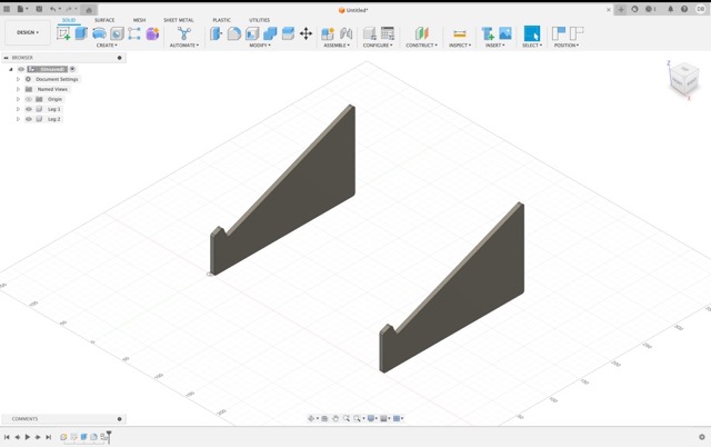
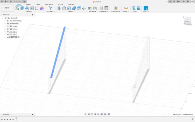
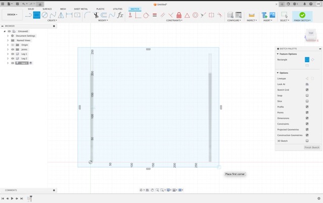
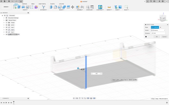
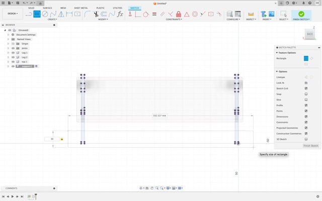
Once verified that the parameter works correctly: Select a top plane and the top part of a leg and generate a new sketch. From this sketch create a rectangle. This will be our top part of the stand where the laptop will be standing.
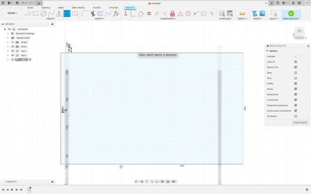
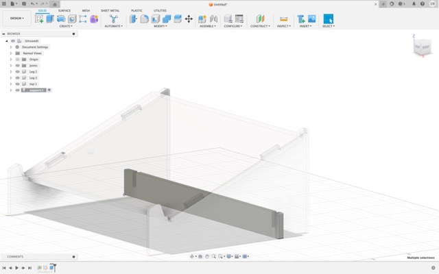
Adjust, as you see fit, the top part so that it reflects with the legs. Next, generate the holes from which the press-fit parts will fit in.
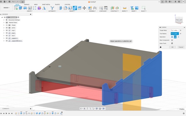
After that, return to the 3D Model and select the combine tool. Then cut the top part of the stand so that the press-fit connections generate.
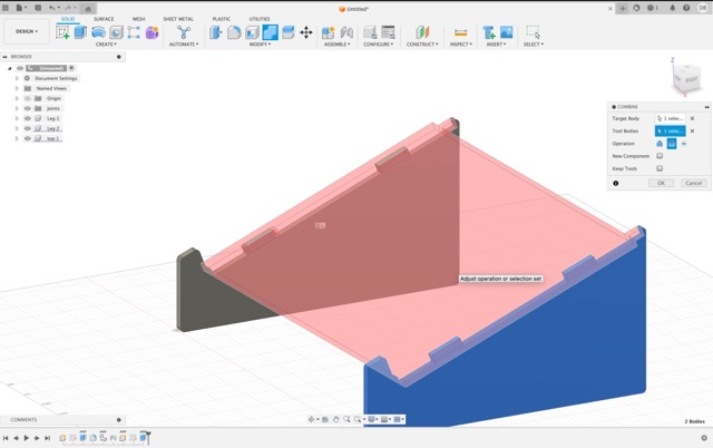
Finally, add the press-fit connections from the bottom side of the stand by following a similar process mentioned above.
Use the constraints tool in order to fit the connections with the stands.
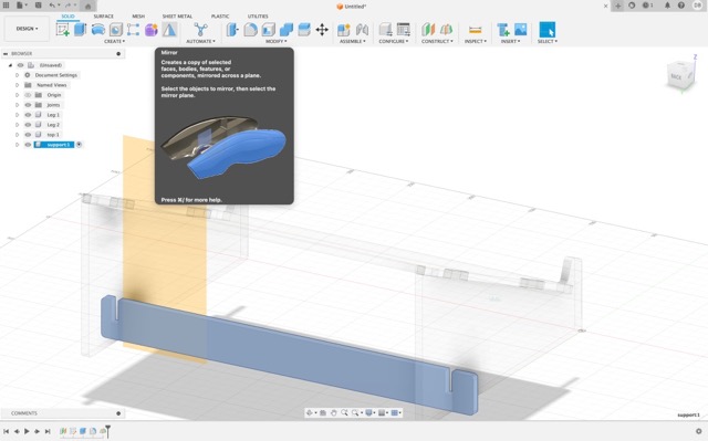
Use the mirror tool to create the other connection.
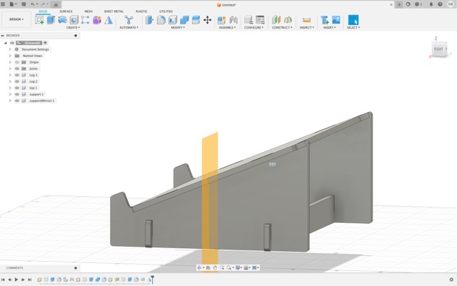
And we are done!
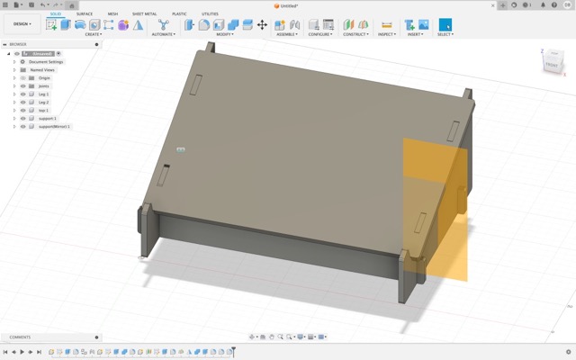
Here is the 3D model in Sketchfab:
The original files can be downloaded here: {Laptop Stand v1.f3d} {Laptop Stand v2.obj}
However, even though I succesfully designed a Laptop Stand, navigating the intricacies of Fusion 360's parametric capabilities proved to be more complex than anticipated.
I encountered difficulties in achieving the exact dimensions and tolerances required for the pieces to fit together seamlessly. This initial foray into the project, despite not meeting the activity's requirements, was far from futile. It offered a valuable learning experience, shedding light on the limitations and possibilities of my design approach and the software tools at my disposal.
The (weird) hexagonal piece
Motivated by the lessons learned from the laptop stand, I ventured into the design of a hexagonal piece, envisioning a modular element that could introduce a new level of interconnectivity and versatility to the construction kit.
This piece featured various openings in its sections, designed to accommodate different configurations and connections.
A very low quality timelapse of my process of making the hexagonal piece:
However, the journey was met with unforeseen technical hurdles.
Specifically, I faced challenges in Fusion 360 when attempting to combine all the pieces due to an error in calculating the precise angles needed for a perfect fit. (As seen in the video where, when selecting 6 times the triangle it had giant gaps that didn't allow the triangles to combine). However, I was able to fix this error by forcing the 60° angle in both sides of the triangle. This was the final (and beautiful) result.
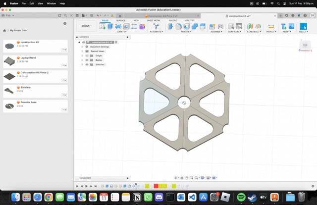
Despite these obstacles, the hexagonal design reached completion. Yet, it became evident that, like its predecessor, it did not fully align with the vision for the construction kit. It offered a glimpse into the potential for modular design but fell short in practicality and ease of assembly, which were key aspects of the project's goals.
Here is the model in sketchfab
The original files can be downloaded here: {Construction Kit v2.f3d} {Construction Kit v2.obj}
The real one.
The experiences gleaned from these initial attempts were invaluable. They not only highlighted the complexities of working with advanced design software like Fusion 360 but also underscored the importance of adaptability and resilience in the face of design challenges.
In the midst of navigating the complexities of designing a construction kit with Fusion 360, I reached a point where the guidance provided at our local FabLab seemed insufficient for overcoming the challenges I faced. Seeking clarity and expertise, I decided to return to a familiar and supportive environment—my previous workspace at the Maker space in the American School of Puebla. It was there that I reconnected with Hugo Teutli, not only my former boss but also a trusted mentor and friend. His presence and willingness to assist became a pivotal turning point in the project's development.
The American School of Puebla:
Hugo's expertise in design and fabrication proved invaluable. He patiently reviewed the designs I had struggled with, pinpointing the critical issues that eluded me. Together, we delved into the nuances of Fusion 360, addressing the parametric and fitting problems that had stymied my progress with the laptop stand and the hexagonal piece.
His insights into the software's capabilities and how to effectively leverage its tools were enlightening, offering a new perspective on how to approach my designs.
And those enlightening moments led me to reassess and refine my approach, culminating in the creation of a new square base design.
This innovative design was a breakthrough, providing the foundation for a truly versatile construction kit. The square base was engineered to accommodate all pieces, enabling the assembly of a diverse range of structures, including cars, towers, houses, and much more. This versatility was exactly what the project needed, marrying the concepts of modularity, ease of use, and creative freedom.
Hugo's guidance was instrumental in refining the square base design, transforming it into the cornerstone of the construction kit. He provided practical advice on dimensions, tolerances, and the optimization of press-fit connections, ensuring the pieces would assemble seamlessly.
.png)
.jpg)
.jpg)
.jpg)
.jpg)
Here is the 3D model in Sketchfab:
The original files can be downloaded here: {Construction Kit Piece 2 v3.f3d} {Construction Kit Piece 2 v3.obj}
However, there was still a fundamental puzzle to be solved, and that was the hexagonal piece.
After several iterations and overcoming initial design challenges with the hexagonal pieces, I realized that further modifications were necessary to transform them into true building blocks for the construction kit.
I've introduced precision-cut slots along the edges of each hexagon, which are crucial for the interlocking mechanism that allows the pieces to fit together securely.
After making this hexagon based on the previous design of the weird hexagon and adapting it. I decided to cut it out with the laser cutter to see how it fitter. However, to no one's surprise, the hexagons came out really really wrong.
.png)
.jpg)
And, when trying to fit it with the square base design, well...
.jpg)
However, this is where my parametric design came in clutch because I just needed to change one parameter in order for them to fit correctly (which can be seen in the last part of the video).
After modifying the parameters in order for the width to be correct. I placed it once again in the laser cutter.
.jpg)
And, after cutting it out, I checked once again to see if it all fitted... And wow!
.jpg)
Before and after:
.jpg)
Here is the 3D model in SketchFab:
The original files can be downloaded here: {Construction Kit v6.f3d} {Construction Kit v7.obj}
This development in the design was essential. It provided the modularity that was missing in my earlier attempts. The slots not only facilitate easy assembly and disassembly but also encourage experimentation with the kit, enabling me to construct a wide array of structures. I can now use these pieces to build models of varying complexity and design, from simple shapes to more elaborate forms like cars, towers, or houses.
Seeing these revised hexagonal pieces in the image, I feel a sense of accomplishment. I've managed to create a versatile and engaging construction kit that captures the essence of what I set out to achieve. The journey from the initial concept to this final design is a testament to the power of persistence, the importance of seeking guidance, and the joy of creative problem-solving in the world of design and fabrication.
And all that was left to do is cut more pieces and then we can begin creating things!
.jpg)
Let's get CREATIVE!
With the newly designed hexagonal pieces, now featuring interlocking slots, the construction kit has opened up a world of possibilities for creating various figures and structures. One of the most exciting aspects of this kit is that it empowers me to leverage my imagination to its fullest potential.
.jpg)
For instance, constructing a house is a straightforward task with these pieces. By interlocking the hexagons to form walls and stacking them to create multiple levels, I can design a multi-story building with ease. The slots allow for the addition of a roof by angling pieces together, thus completing the house structure.
.jpg)
.jpg)
.jpg)
However, we can make even more crazy things. It's fascinating to see how, by strategically positioning and interlocking these pieces, I've built a tower that spirals upwards, resembling a vortex.
.jpg)
.jpg)
.jpg)
.jpg)
.jpg)
The versatility of the pieces even extends to creating functional items like a table. By assembling the hexagons in a flat, horizontal layout and then using additional pieces as legs, I can put together a sturdy table. But it doesn't stop there; with some creativity, that same table can transform into a car. By reconfiguring the pieces and perhaps adding wheels if the kit includes them, the structure takes on a new life as a toy vehicle.
.jpg)
Beyond these practical figures, the construction kit invites exploration into the realm of abstract art. With no rules or limitations, I can experiment with the hexagons to create sculptures that are as unique as they are expressive. The interlocking mechanism allows for secure connections at various angles, enabling me to construct intricate and visually captivating artworks that reflect my personal style and vision.
The true beauty of this construction kit lies in its ability to be as boundless as my imagination allows. Whether I'm interested in creating models that mimic real-world objects or venturing into the abstract and experimental, the kit provides a foundation for endless creativity. It's not just about what I can build but also about the process of discovery and innovation that comes with each new creation.
Vinyl Cutter
During our time at the fab, we encountered a situation with the person in charge of the vinyl cutter, which made it difficult for us to use the primary machine for our project. In response to this challenge, all of the students came together in a collaborative effort to learn how to operate a new, smaller vinyl cutter—the Silhouette Portrait 3. This decision was born out of our collective necessity to continue with our practice and our shared commitment to our learning.
.jpg)
The Silhouette Portrait 3 is a compact and versatile vinyl cutter that is particularly well-suited for small-scale projects or personal use. It's an excellent tool for cutting a wide range of materials, including vinyl, cardstock, fabric, and more. One of the key features of the Portrait 3 is its ability to perform a "kiss cut," which only cuts through the vinyl and leaves the backing intact, making it perfect for creating stickers and decals. Additionally, the machine can register and cut printed materials, thanks to its optical sensor, which allows for precise contour cutting around designs that are printed on a compatible printer.
.png)
The Silhouette Portrait 3 operates in conjunction with Silhouette Studio, the accompanying software that is used to design and send projects to the cutter. Silhouette Studio is user-friendly and provides a broad range of design tools, making it accessible for beginners while also offering advanced features for more experienced users. In the software, I can paste my image or design, adjust it to the desired size, and add cut lines as necessary. Once the design is ready, the software sends it to the Portrait 3, which then accurately cuts the design according to our specifications.
In the spirit of collaboration and taking advantage of our newly acquired skills with the Silhouette Portrait 3 vinyl cutter, I decided to create a sticker of the logo for my university's Esports team, the Gansos. This project was not only a way to showcase my team spirit but also an opportunity to apply what we had learned about the vinyl cutting process.
.jpg)
Using the Silhouette Studio software, I imported the Gansos' logo into the workspace. Carefully, I ensured the design was optimized for vinyl cutting, checking that the size was appropriate and that the cut lines were precise. The software's intuitive interface allowed me to make any necessary adjustments easily, preparing the logo for the cutting process.
Once the logo was ready, I sent the design from Silhouette Studio to the Portrait 3. The machine's precision cutting feature was ideal for capturing the intricate details of the Gansos' logo, ensuring that the final sticker would be a high-quality representation of the team's branding.
.jpg)
I chose a green vinyl color because that was the only vinyl we had been provided until that moment, and after the Portrait 3 finished its work, I had in my hands a professional-looking sticker.
.jpg)
.jpg)
However, I still wanted my vinyl to be red. So I went with my local instructor, Prof. Rafa, and he gave me some red vinyl he had :)
.jpg)
Creating this sticker was a rewarding experience, as it served as a tangible representation of the skills we had collectively learned and the problem-solving capabilities we had developed in response to the initial setback with the primary vinyl cutter. Moreover, it was a symbol of my pride in our Esports team and a personal contribution to the team's identity, providing a sense of accomplishment and team unity.
Conclusion
In conclusion, the journey through the world of digital fabrication with both the vinyl and laser cutters was filled with learning opportunities, challenges, and ultimately, success. The Silhouette Portrait 3 vinyl cutter opened up new avenues for creativity and collaboration, as we students banded together to overcome obstacles and master a new tool. The creation of the Gansos Esports team sticker was a perfect example of how we could apply our newly developed skills to produce meaningful and personal projects.
Similarly, the laser cutter experience, from initial difficulties with design and operation to the successful production of a versatile construction kit, showcased the importance of persistence and adaptability. Each step of the process, from the initial concept to the final product, was a lesson in the potential of digital fabrication tools to bring ideas to life.
Both the vinyl and laser cutting experiences highlighted the value of mentorship, hands-on learning, and the Maker community's collaborative spirit. Whether crafting intricate designs with the laser cutter or producing custom stickers with the vinyl cutter, these experiences have enriched my understanding of the design process and expanded my ability to translate concepts into tangible objects.
The vinyl and laser cutters are more than just machines; they are gateways to innovation, allowing for the expression of creativity and the realization of complex projects. As I continue to explore the possibilities within digital fabrication, I carry with me the lessons learned from these experiences—the tenacity to troubleshoot, the willingness to seek guidance, and the excitement of transforming an idea into reality.
The Files:
Below you can find the download links for all of the files from this week.