Week 2: Computer Aided Design
Overview
For this week's assignment, I designed the structure of my project using Tinkercad for the 3D design portion. While I have extensive experience with professional CAD software—including Rhino, Maya, SolidWorks, Solid Edge, Inventor, Fusion 360, NX, and Ansys Finite Element Analysis—this was my first time using Tinkercad, and it definitely took me by surprise.
I wouldn’t call it complicated, because it isn’t. However, being accustomed to parametric modeling with a history-based workflow where modifications can be made seamlessly, adapting to Tinkercad’s approach was a fun challenge. While I wouldn’t use it for advanced design work, I genuinely appreciated the experience of working within its constraints.
For the 2D design, I had no difficulties since I used Adobe Illustrator, which also set the foundation for next week’s task—cutting my final project’s logo in vinyl. This will be the first iteration of what will eventually become a refined brand identity for AquaBudz.
Checklist
- ✅ Modelled experimental objects/part of a possible project in 2D software
- ✅ Modelled experimental objects/part of a possible project in 3D software
- ✅ Documented how you compressed your image and video files
- ✅ Include your original design 2D files
- ✅ Include your original design 3D files
- ✅ Include a 3D View of my design
- ✅ Tinkercad VS Fusion 360
- ✅ Fusion 360 Stress Analysis
Tools I Used
| Tool | Description |
|---|---|
| Tinkercad | Tinkercad is a free, web-based 3D modeling tool popular for 3D printing and introductory geometry learning in schools since 2011. |
| Adobe Illustrator | Adobe Illustrator is a vector-based design software used for creating logos, illustrations, and graphics, widely popular among designers since its launch in 1987. |
Tinkercad Tools
| Command | Purpose |
|---|---|
Model & Simulation

|
Used for designing, analyzing, and rendering objects. | Group

|
Combines multiple shapes into one solid object. |
Ungroup

|
Separates grouped shapes back into individual objects. |
Align

|
Positions objects precisely along shared axes. |
Duplicate

|
Creates an exact copy of an object for quick modeling. |
Scene

|
The environment where materials, colors, and object appearances are adjusted. |
3D Modelling: Tinkercad Interface
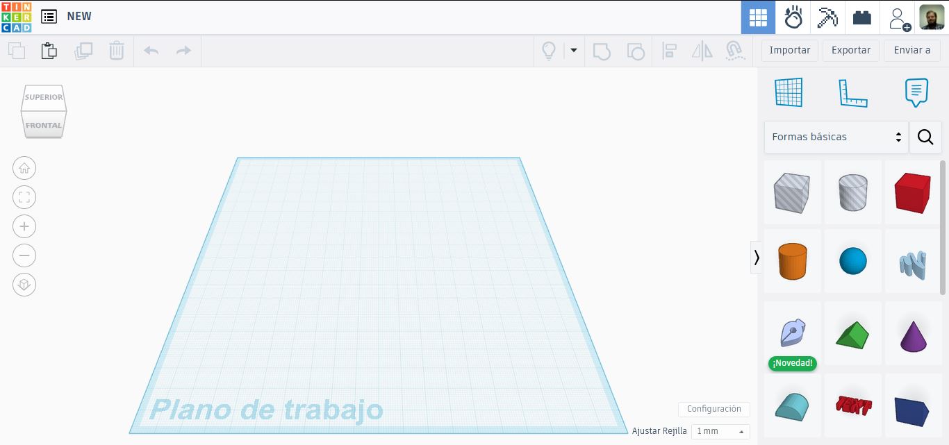
Like most Autodesk software, Tinkercad features a familiar navigation system. On the left side of the screen, you’ll find essential view controls, including:
- The View Cube for quick orientation.
- Home View to reset the camera.
- Zoom to Fit/Selection to focus on specific areas.
- Zoom In and Out for adjusting the view.
- Perspective and Orthographic View toggles.
At the center of the screen is the workplane, where all the magic happens. This is your primary workspace for creating and modifying designs.
Since my interface is in Spanish, some translations might not be exact compared to the English version, but the general layout remains the same.
On the right side, you’ll find tools such as:
- Rulers to help with precise alignment.
- Planes for reference positioning.
- Comments for collaboration.
- A library of shapes—from basic geometric forms to more complex pre-made models.
While Tinkercad is often seen as an entry-level CAD tool, designed primarily for beginners and students, it has some surprisingly powerful features. The top toolbar contains essential tools such as:
- Group & Ungroup to combine or separate objects.
- Align to position components precisely.
- Duplicate to quickly copy elements.
Despite its simplicity compared to advanced parametric CAD software, Tinkercad offers a refreshing and intuitive approach to 3D modeling, making it a great tool for quick prototyping and creative exploration.
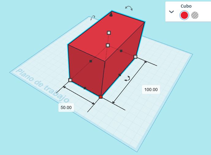
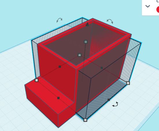
3D Modelling: Boolean Operations
In this step, we will create a solid cube, then use a hollow cube to subtract material, forming an empty space inside. In Tinkercad, Boolean operations are simplified through the Group tool, making it easy to combine or subtract objects.
Understanding Grouping in Tinkercad:
- Grouping two solid objects → Merges them into a single piece.
- Grouping a hollow object with a solid one → Subtracts the hollow shape from the solid, creating a cutout.
This feature makes Boolean operations much simpler than in parametric CAD software, where you typically need to manually apply subtraction or union functions.
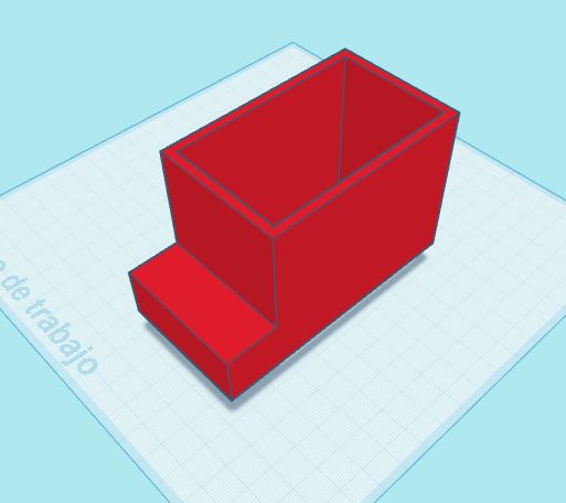
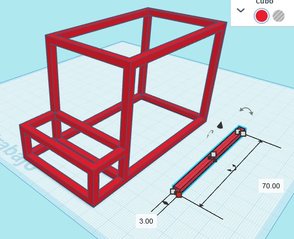
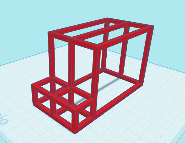
Visual Guide: Boolean Operations
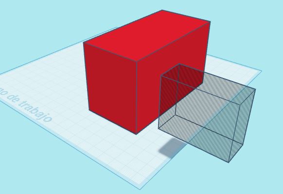
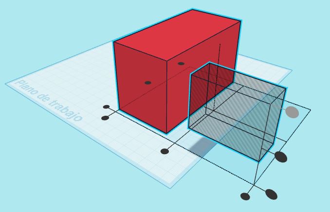
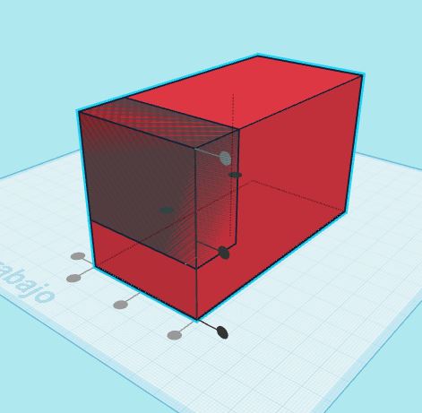
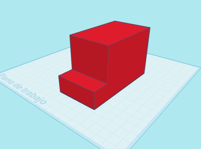
The Boolean process continues as I create, align, and subtract shapes, gradually refining the design. Starting with basic cubes, I manipulate them using Tinkercad’s intuitive grouping and subtraction tools.
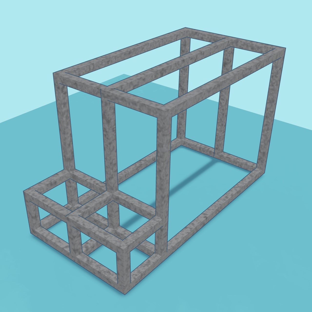
Each step helps define the structure, making it increasingly recognizable as the foundation of the hydroponic garden. By strategically subtracting hollow shapes from solids, I carve out **functional sections** where components like plant holders, water channels, and structural supports will fit.
Below, you can see a series of images illustrating this transformation—from simple geometric shapes to a structure that begins to resemble the structure of the hydroponic garden.
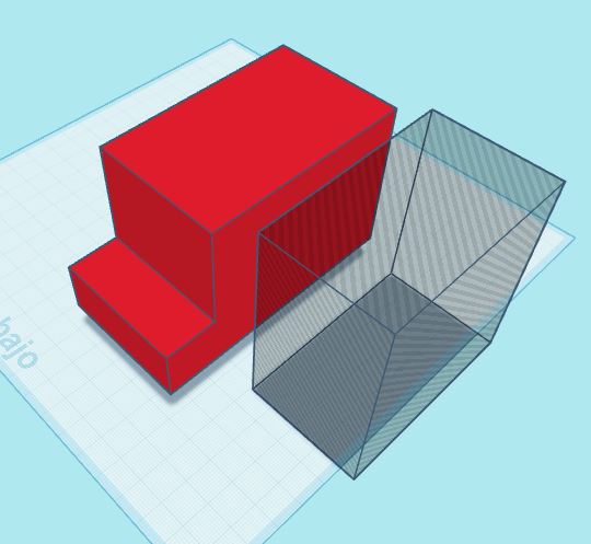
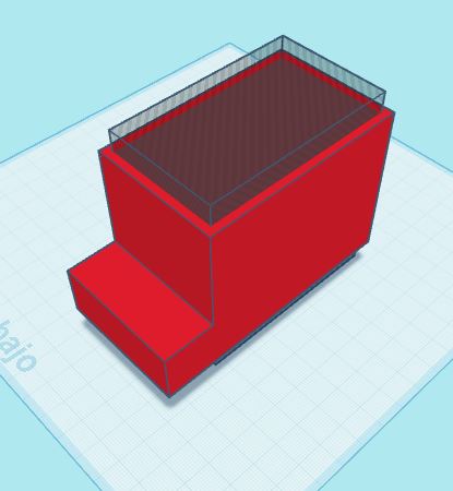
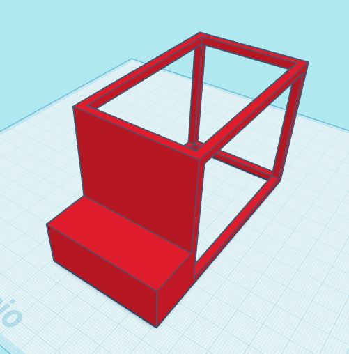
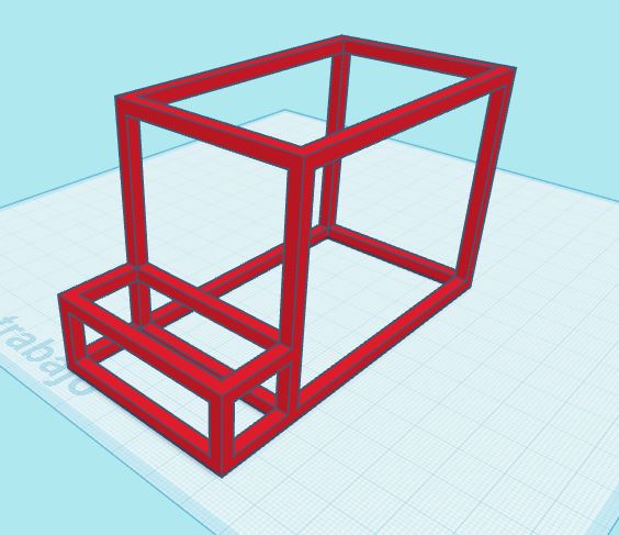
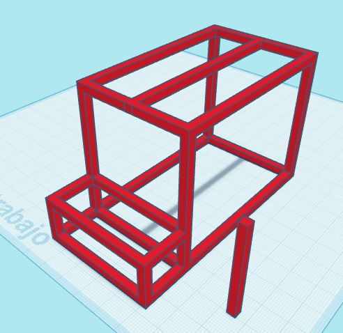
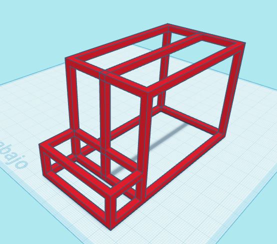
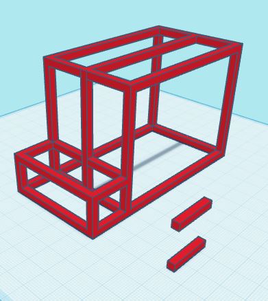
After defining the base structure, the next step involves creating additional structural elements and integrating them into the main aluminum frame. Unlike the previous step, which focused on removing material through Boolean operations, this stage is about adding new components to enhance the structure.
The purpose of this step is to demonstrate how to design supplementary elements—such as reinforcements, support brackets, or attachment points—and properly align and group them with the primary structure. This ensures a rigid and functional design that can support all necessary hydroponic components.
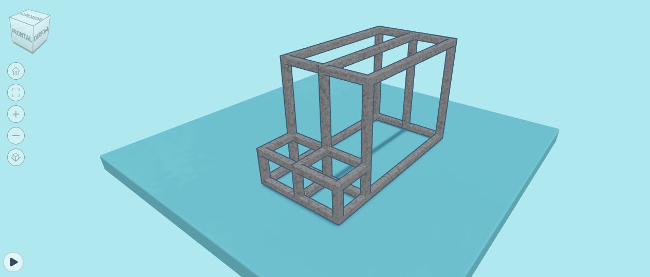
The final step in the design process is rendering. While advanced software like Maya allows for photorealistic rendering with fine-tuned lighting, reflections, and materials, Tinkercad keeps things simple and efficient.
Instead of complex shaders and physically accurate materials, Tinkercad provides a basic rendering tool that focuses on clear, visually appealing representations. The results have a cartoonish yet polished aesthetic, making models look clean and easy to interpret. This is especially useful for beginners, educators, and quick prototyping.
Users can apply colors and materials to objects, as well as modify the surface appearance using the built-in shape and material menu.
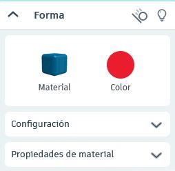
Tinkercad allows users to customize materials and colors for both objects and surfaces. Though it doesn’t support textures or reflections like advanced rendering software, it provides enough flexibility to give a clear visual distinction between different components of a model.
Below are examples of rendering environment from Tinkercad. While the shading is basic, the models maintain a clean, easy-to-interpret look that works well for prototyping and documentation.
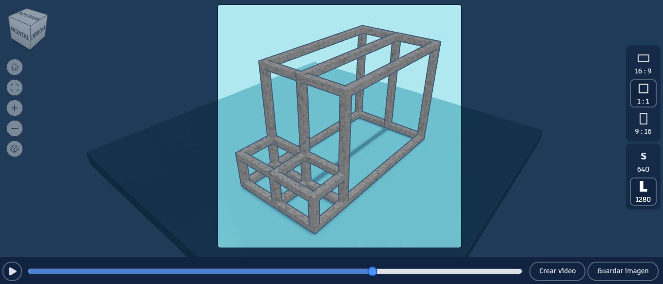
Once the design is complete, the model can be exported as an STL file (visualizador 3D), making it ready for 3D printing and further processing in other CAD or slicing software.
You can download the OBJ (ZIP) and the STL file for 3D printing here:
3D Viewer
To better visualize the hydroponic structure, I have embedded an interactive 3D model below. This allows you to inspect the design from different angles, zoom in on details, and understand its geometry before fabrication.
Click and drag to rotate the model, use the scroll wheel to zoom in/out and interact with the structure in real time.
Below is the optimized code I used for embedding an interactive 3D model viewer in my webpage. You can explore more features, documentation, and customization options at Model Viewer.
        <!-- Import the Model Viewer component -->
        <script type="module" src="https://ajax.googleapis.com/ajax/libs/model-viewer/4.0.0/model-viewer.min.js"></script>

        <!-- 3D Model Viewer -->
        <model-viewer
            src="files/hydroStructure-v1.glb"
            camera-controls
            auto-rotate
            shadow-intensity="1"
            environment-image="https://modelviewer.dev/shared-assets/environments/moon_1k.hdr"
            camera-orbit="0deg 90deg 10m"
            field-of-view="75deg"
            style="width: 50%; max-width: 400px; height: 200px; margin: auto; display: block; margin-bottom: 20px;">
        </model-viewer>
2D Design: AquaBudz Logo
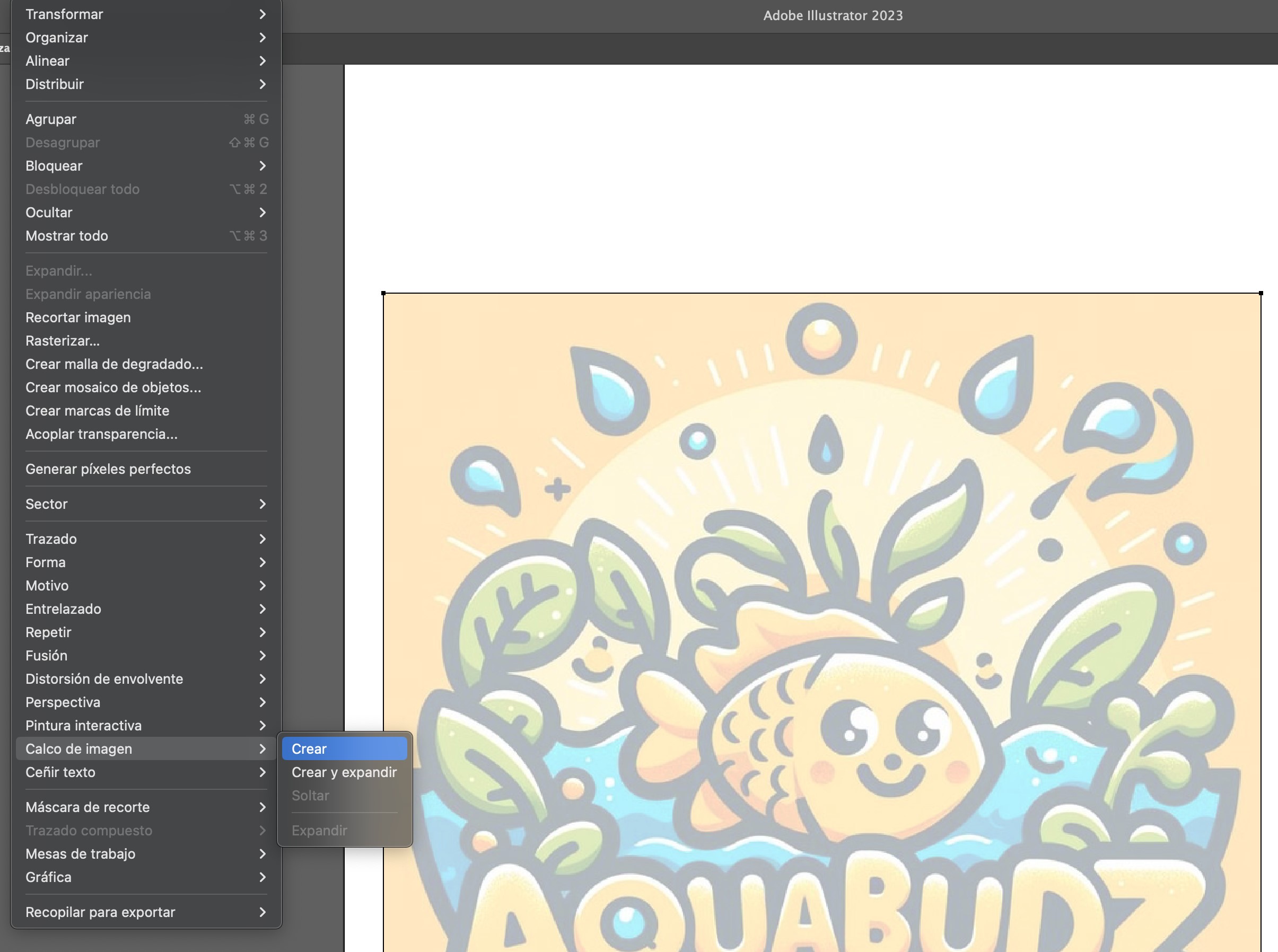
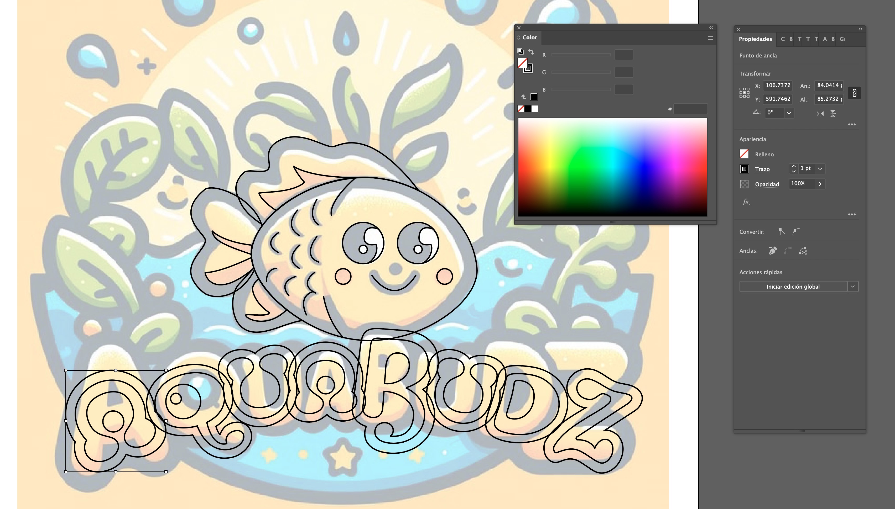
For this step, I created a vectorized version of an image using Adobe Illustrator. While Illustrator offers a quick and easy Image Trace tool, I opted for a more precise and hands-on approach by manually tracing the image with the Pen Tool.
The original image was generated using DALL·E, an AI image-generation tool. The prompt used to create the image was: The logo should use a bright yellow color palette and feature playful elements such as a smiling fish, sprouting plants, and water droplets, all designed to be appealing and approachable for a young audience.

Vectorization Tools
| Tool | Purpose |
|---|---|
DALL·E |
AI image-generation tool used to create the original fish illustration, serving as a base for vectorization. | Adobe Fonts |
Provided a wide selection of typefaces, helping to find the right font for the "AquaBudz" logo. |
Pen Tool |
Used to manually trace and create precise vector paths with adjustable anchor points. |
Ellipse Tool |
Created basic circular and oval shapes for organic elements like fins. |
Pathfinder Tool |
Combined, merged, or subtracted shapes to refine the structure and details. |
Transparency Adjustment |
Made a semi-transparent reference layer to aid in manual tracing without obscuring the workspace. |
Color Picker & Swatches |
Selected and applied a custom color palette to enhance contrast and visibility. |
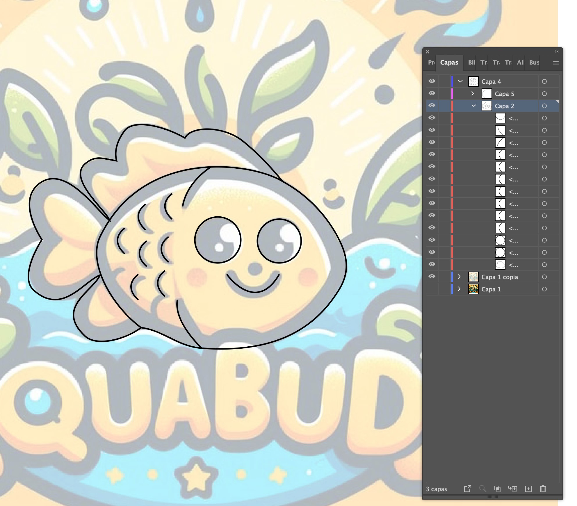
Layer Management |
Organized different elements (base shape, details, decorations) to maintain a structured workflow. |
Text Tool |
Typed and adjusted the font into an arched shape to fit the overall composition. |
Export as SVG |
Saved the final vector file for further processing and vinyl cutting |
The process begins by importing the selected image into Illustrator. To ensure a cleaner workflow, I created a duplicate of the image and reduced its transparency. This allows me to use it as a reference while keeping the original hidden for a final comparison.
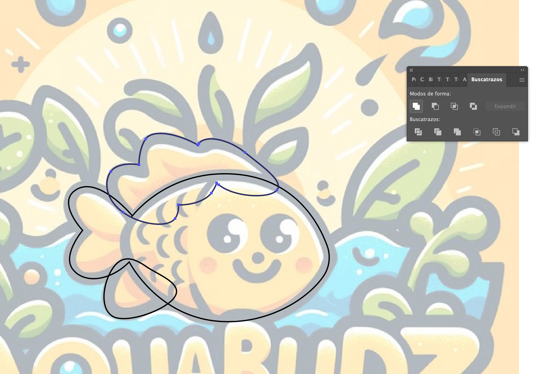
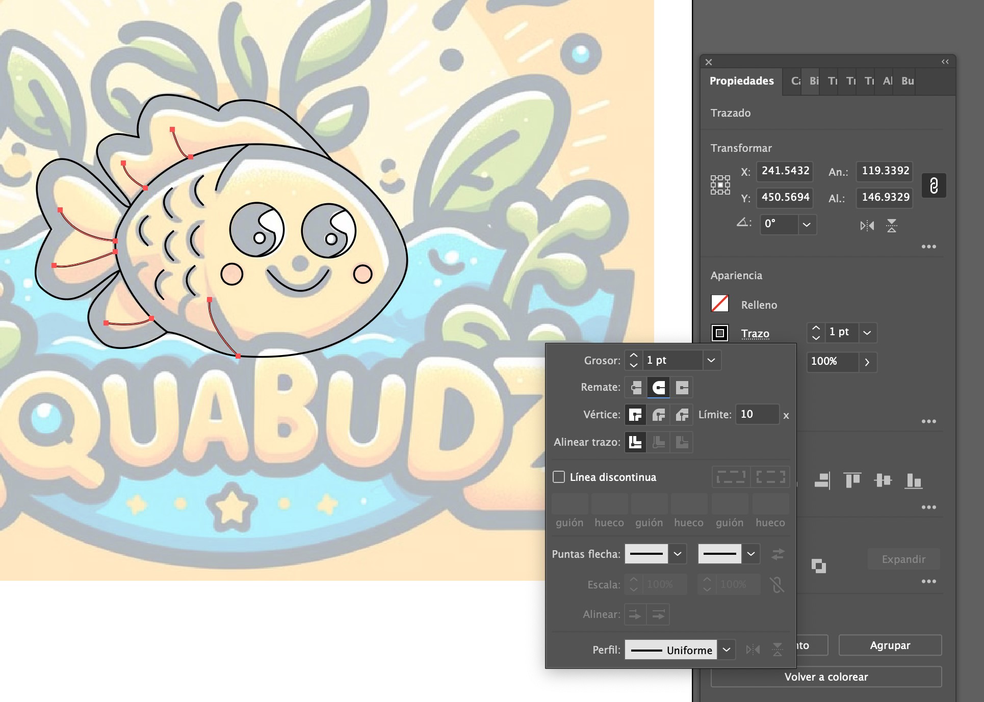
Once the reference layer is set, I started manually tracing the image using the Pen Tool. This tool allows for greater control over curves and sharp angles, ensuring a more refined and editable vector design.
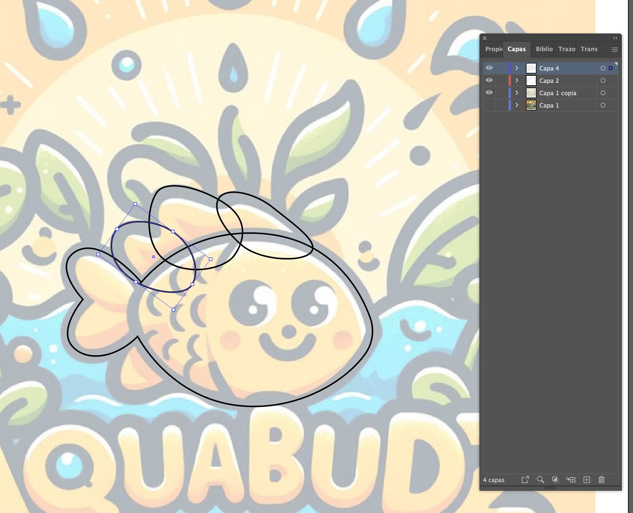
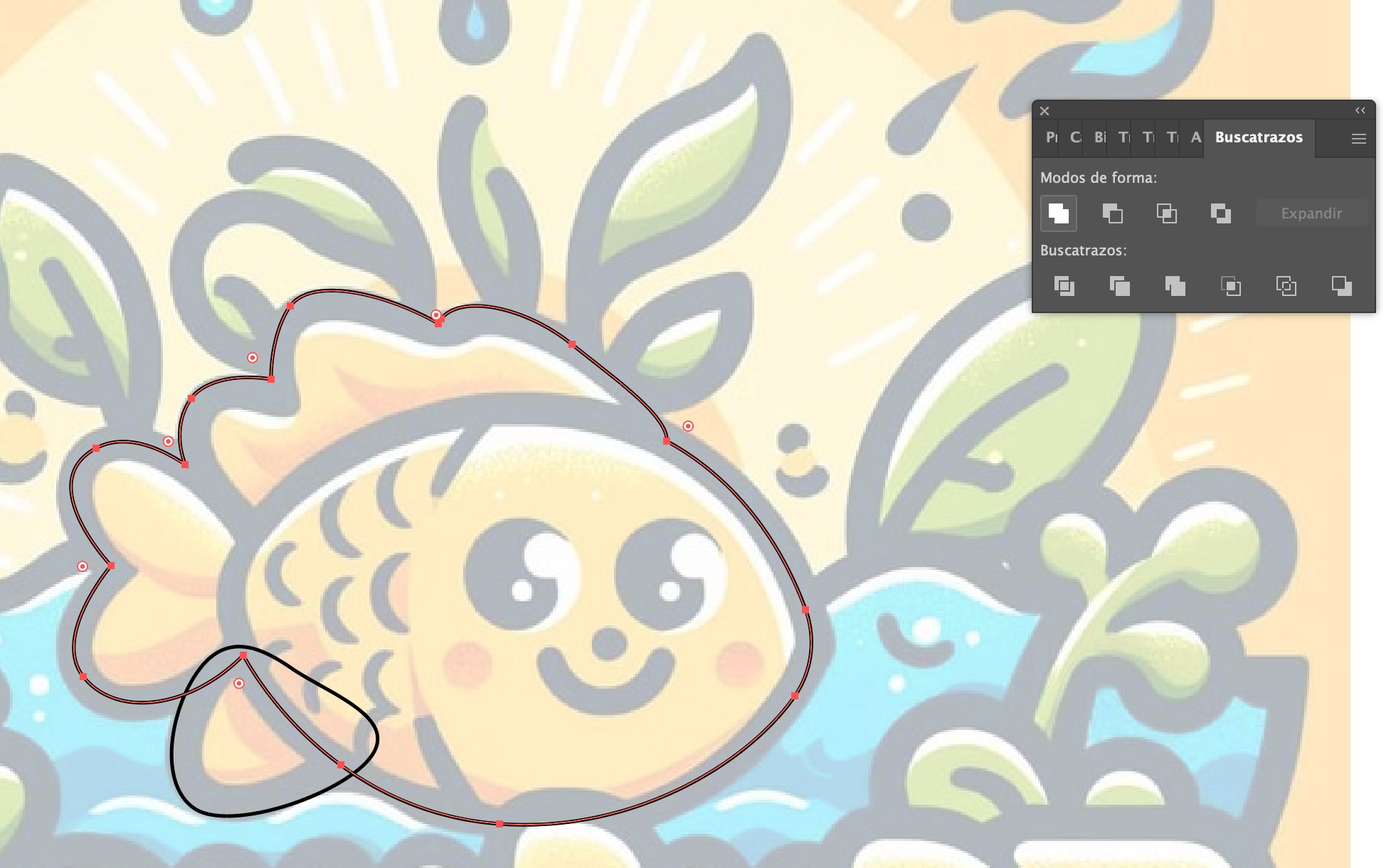
For elements like fins and curves, I used the Ellipse Tool and manipulated anchor points to create smooth organic shapes. Adjusting these points allows for more precise control over the final design.
To merge different shapes seamlessly, I used the Pathfinder Tool. This essential tool in Illustrator helps combine multiple objects into a single form, ensuring a smooth transition between the different parts of the illustration.
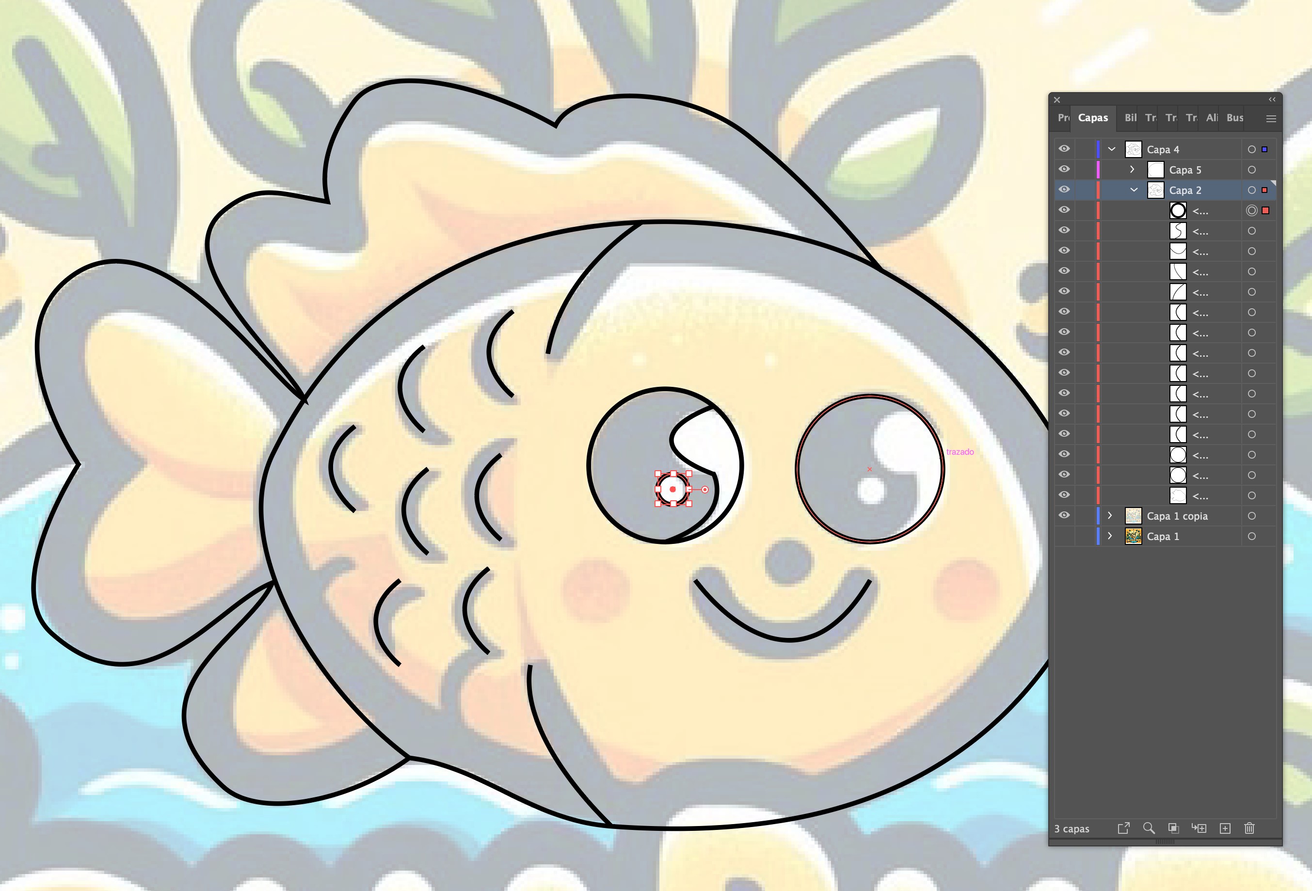
Finally, I added finer details such as the eyes, scales, and outline refinements to bring the vector design to life.
With the vector design complete, the next step was applying colors and additional decorative elements. Instead of simply filling in colors, I carefully selected a custom color palette to enhance contrast and visibility.

To add depth to the scene, I incorporated extra elements such as water waves and plants. These elements were carefully layered in Illustrator to create a visually balanced composition.

The final step in this process was designing the AquaBudz logo. Instead of using a standard font, I used a font recognition tool from Adobe to identify a unique typeface that closely matched the concept.
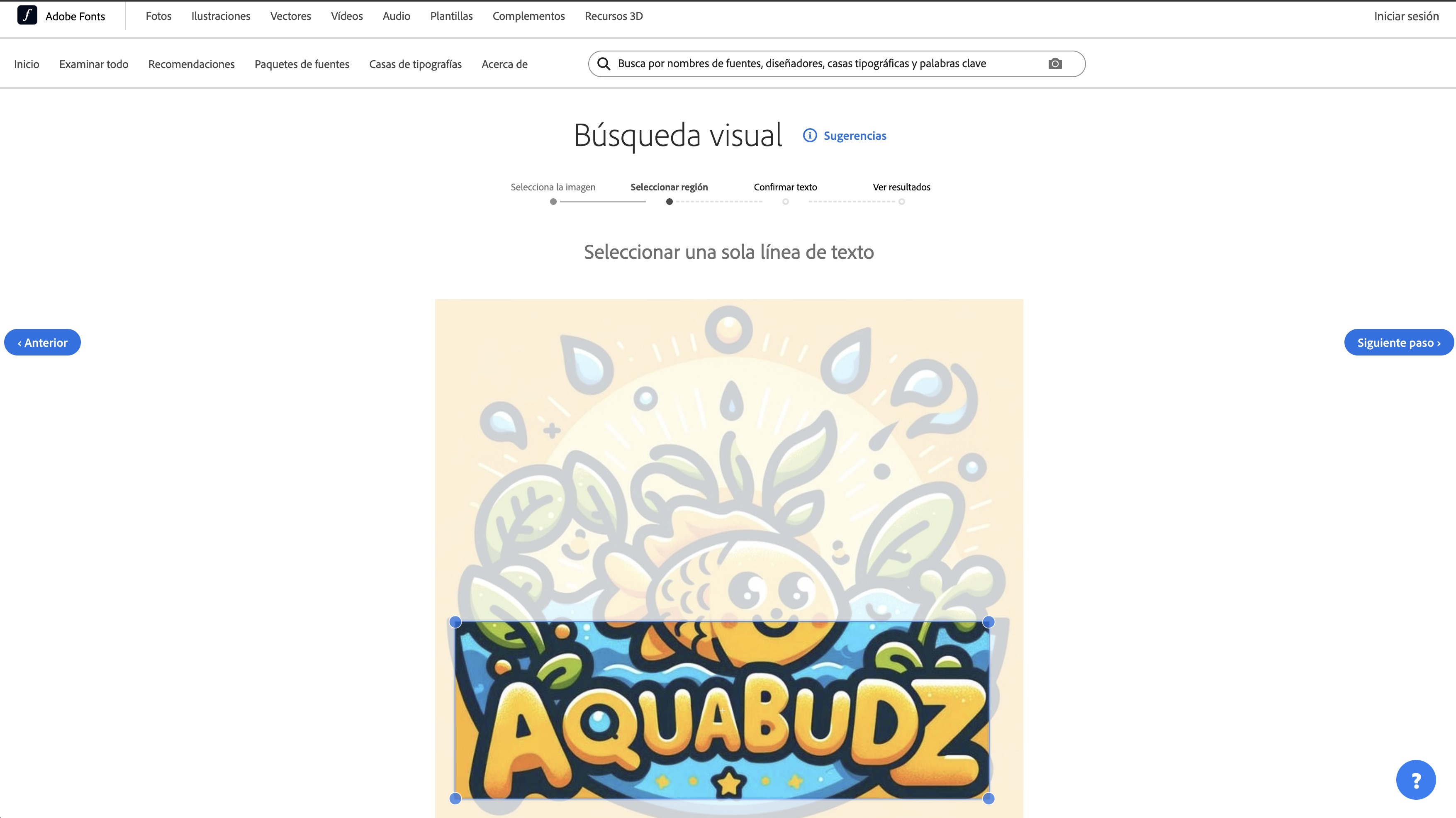
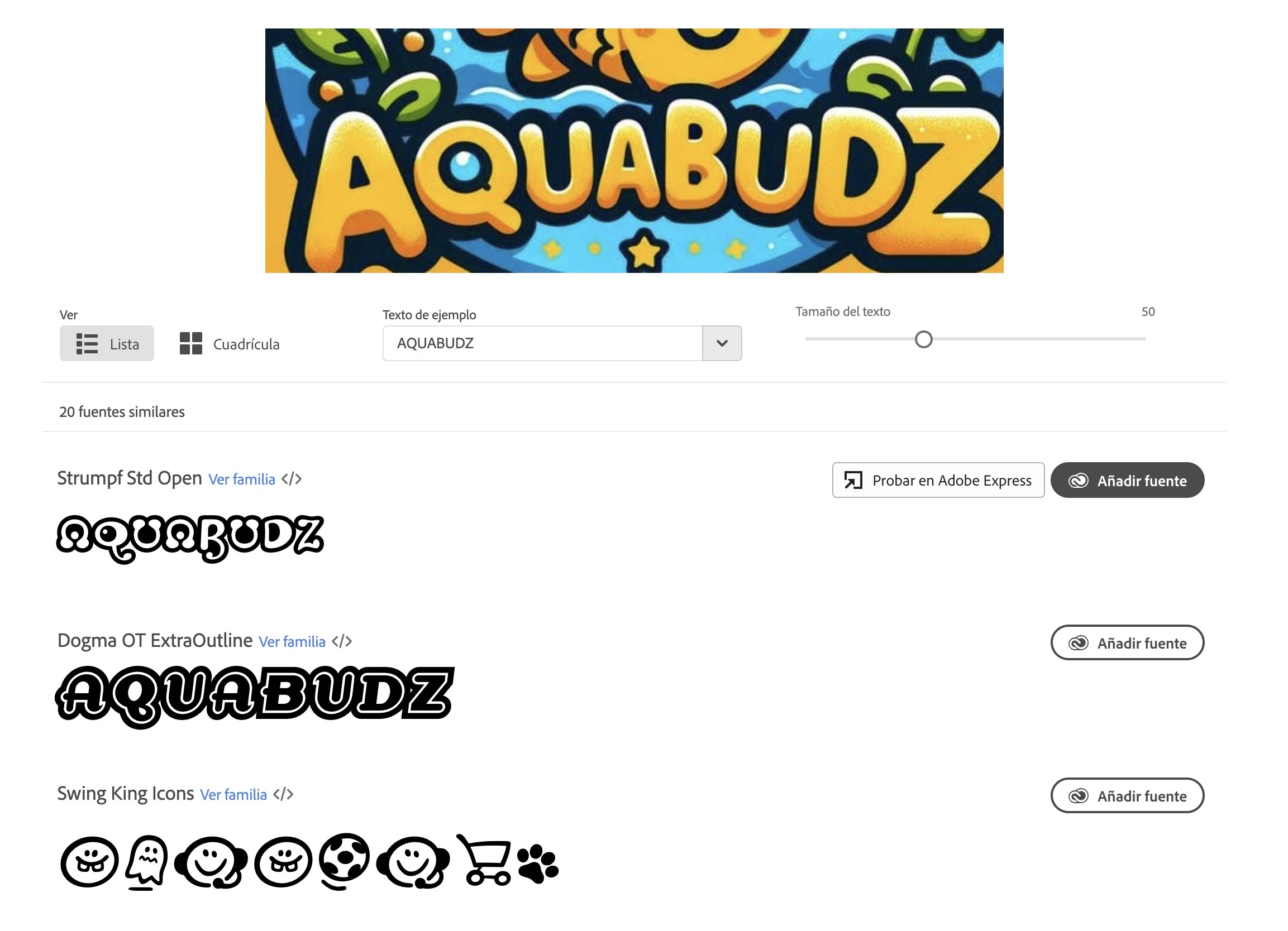
After choosing the font, I shaped it into an arch to fit the design aesthetics. This required careful alignment and transformation to maintain proportionate spacing.
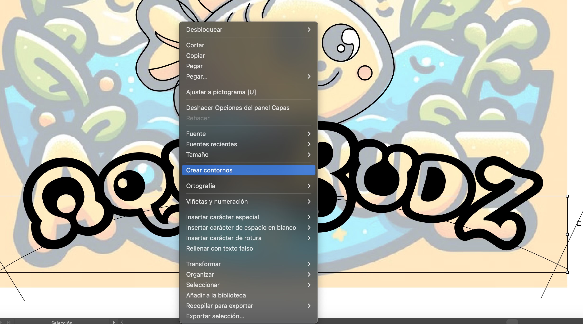
For final refinements, I applied the Image Trace tool selectively to vectorize the text while preserving the crisp edges and details.

With the design finalized, the vectorized AquaBudz logo is now ready for vinyl cutting and further application in digital and physical media.
To illustrate the transformation, here is a side-by-side comparison of the original*DALL-E-generated image and the final vectorized version. The difference highlights the level of precision and refinement that manual vectorization brings to a design.
Sharing Large Files: Why Compression Matters
- Reduces file size for faster uploads and downloads.
- Combines multiple files into one package.
- Ensures compatibility across different operating systems.
Steps to Compress the File
For this week's assignment, I created an Adobe Illustrator file (.AI) and needed to compress it into a ZIP file to make it easier to upload and share.
- Locate the Illustrator file (
aquabudzlogo.ai). - Right-click the file (Windows) or Control+Click (Mac).
- Select "Compress to ZIP" (Windows) or "Compress" (Mac).
- A new ZIP file is created (
aquabudzlogo.zip).
You can download the Illustrator file (ZIP) and the SVG file for vinyl cutting:
Using WhatsApp and GIMP for compression
WhatsApp for Image Compression:
WhatsApp automatically compresses images when sent as a regular photo. This is a quick and effortless way to reduce file size, but some quality loss may occur.

How WhatsApp Compresses Images:
While WhatsApp has not officially disclosed its image compression methods, analysis from this article suggests the following process:
- Resolution Downscaling: WhatsApp resizes images to a maximum of approximately 1600px on the longest side.
- JPEG Recompression: Images are converted to JPEG format, typically with a quality level of around 70-80%.
- Metadata Stripping: All EXIF metadata (such as GPS location, camera settings, and timestamps) is removed.
- Bitrate Optimization: Compression levels may vary based on network conditions.
Steps to Compress an Image Using WhatsApp:
- Send the image to yourself or a contact via WhatsApp.
- Download the image back from WhatsApp.
- Compare the file size – WhatsApp has significantly reduced it.
| Original Image | Compressed Image (WhatsApp) |
|---|---|

|
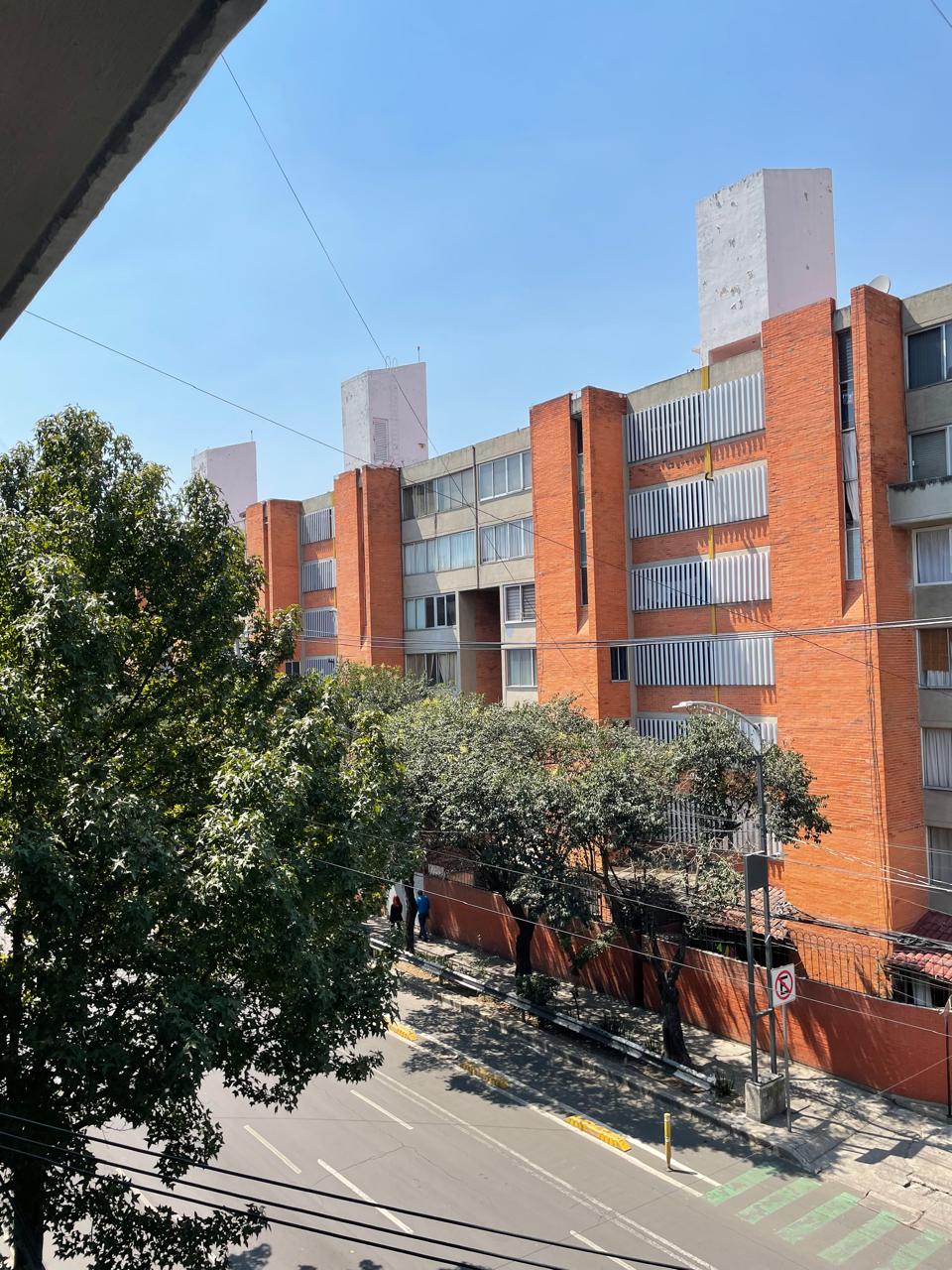
|
| File Size: 3,853 KB; 3024 X 4032 | File Size: 243 KB; 960 X 1280 |
More details on WhatsApp's image quality reduction can be found here.
Using GIMP for Compression
GIMP (GNU Image Manipulation Program) allows you to manually adjust compression settings for better control over file size while maintaining quality.
Supported Platforms: GIMP is available on Windows (7 or newer), macOS (10.12 or newer), Linux, FreeBSD, and OpenSolaris.
System Requirements: Recommended 4GB RAM or more, multi-core processor, and additional storage for plugins. Supports input devices like graphics tablets and MIDI controllers.
Key Features: Customizable interface, advanced photo retouching tools (clone, healing, perspective tools), and extensive plugin support. Supports multiple file formats, including JPEG, PNG, TIFF, and GIF.
Extensibility: GIMP allows scripting in Python, Scheme, Perl, and Tcl for automation. Plugin support enables additional features for editing and effects.
More Information: Visit the official GIMP website for detailed documentation and downloads.

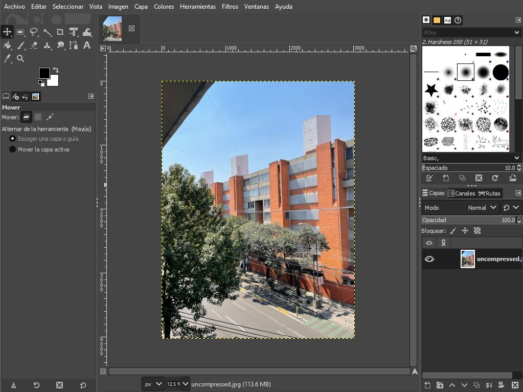
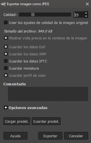
Steps to Compress an Image in GIMP:
- Open your image in GIMP (
File > Open). - Export as a JPEG (
File > Export As). - Adjust compression settings (Set JPEG quality to 25%).
- Click Export and save your optimized image.
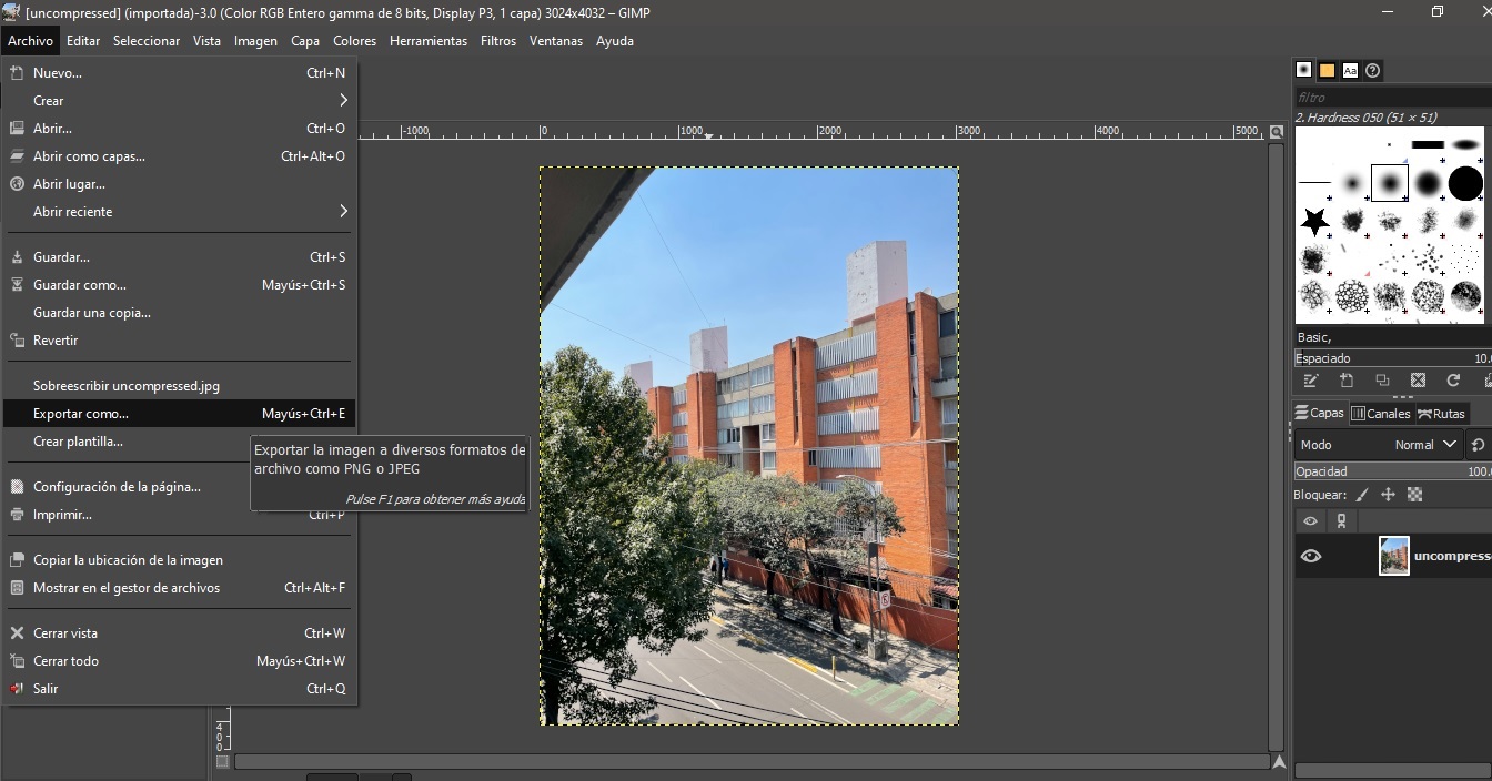
| Original Image | Compressed Image (GIMP) |
|---|---|
|
|
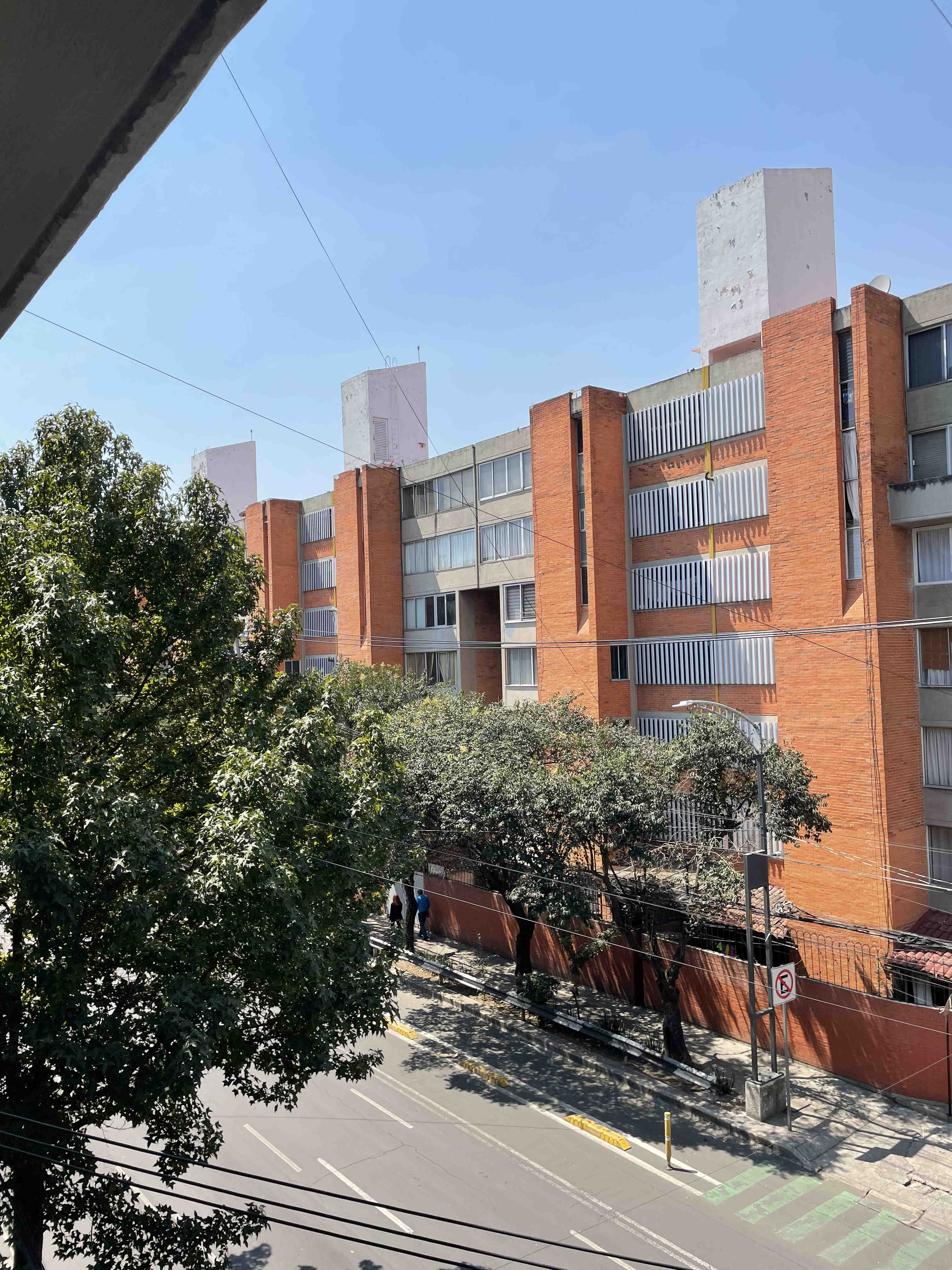
|
| File Size: 3,853 KB; 3024 X 4032 | File Size: 930 KB; 3024 X 4032 |
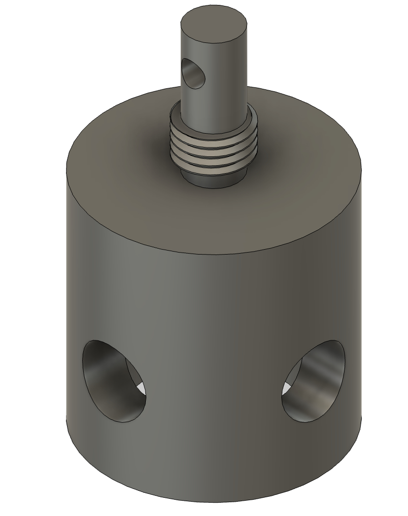
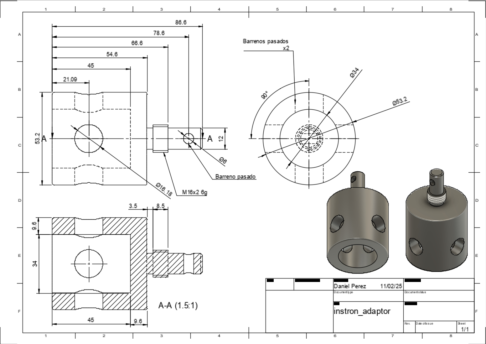
Instron Plate / Load Adapter Design in Fusion 360
This project demonstrates the use of Fusion 360 to design an Instron Plate / Load Adapter, a component that connects a load cell to a plate for mechanical testing.
Using Fusion 360, the design was completed in under 5 minutes, including:
- Creating a single sketch with dimensions and constraints.
- Using the Revolve tool to create a solid model in one step.
- Adding holes for fasteners.
- Performing a stress analysis under a 1kN load.
- Generating a manufacturing drawing for lathe machining.
Fusion 360 vs. Tinkercad
Fusion 360 and Tinkercad are both developed by Autodesk, but they cater to very different users.
| Feature | Fusion 360 | Tinkercad |
|---|---|---|
| User Level | Intermediate to Advanced | Beginner |
| Design Approach | Parametric Modeling | Direct Modeling |
| Best For | Engineering, Manufacturing, Prototyping | Hobbyists, 3D Printing, Simple Models |
| 3D Operations | Revolve, Loft, Fillet, Chamfer, Boolean, Shell | Basic Shape Manipulation |
| Assemblies | Yes (Joints, Motion Simulation) | No |
| Simulation | Stress Analysis, Thermal Analysis | No |
| Manufacturing Drawings | Yes (Technical Drawings, CAM for CNC) | No |
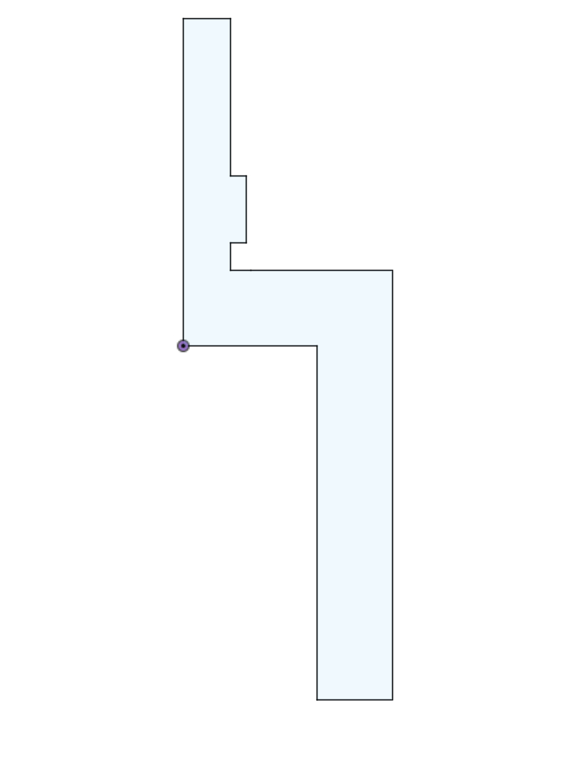
1. Creating the Initial Sketch
The design starts with a single sketch, where I define the profile of the load adapter using lines, and constraints.
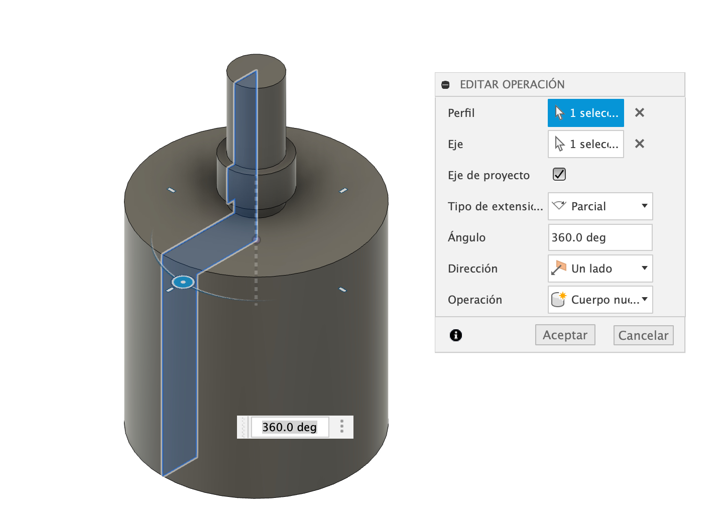
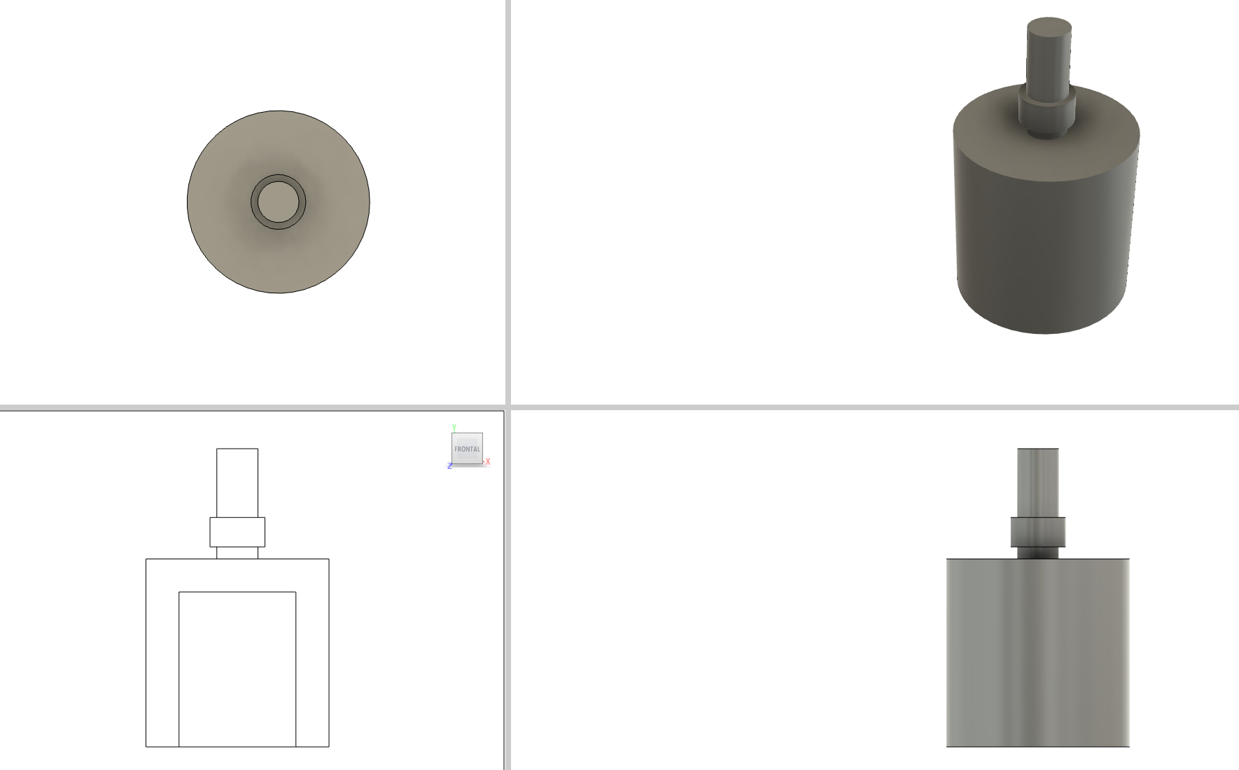
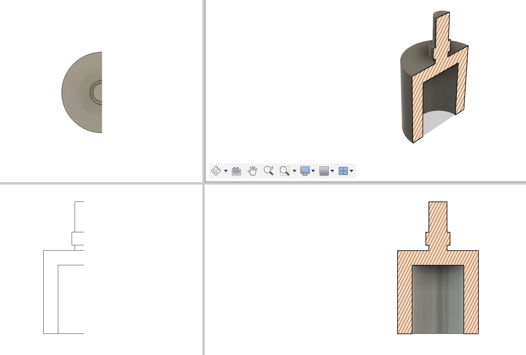
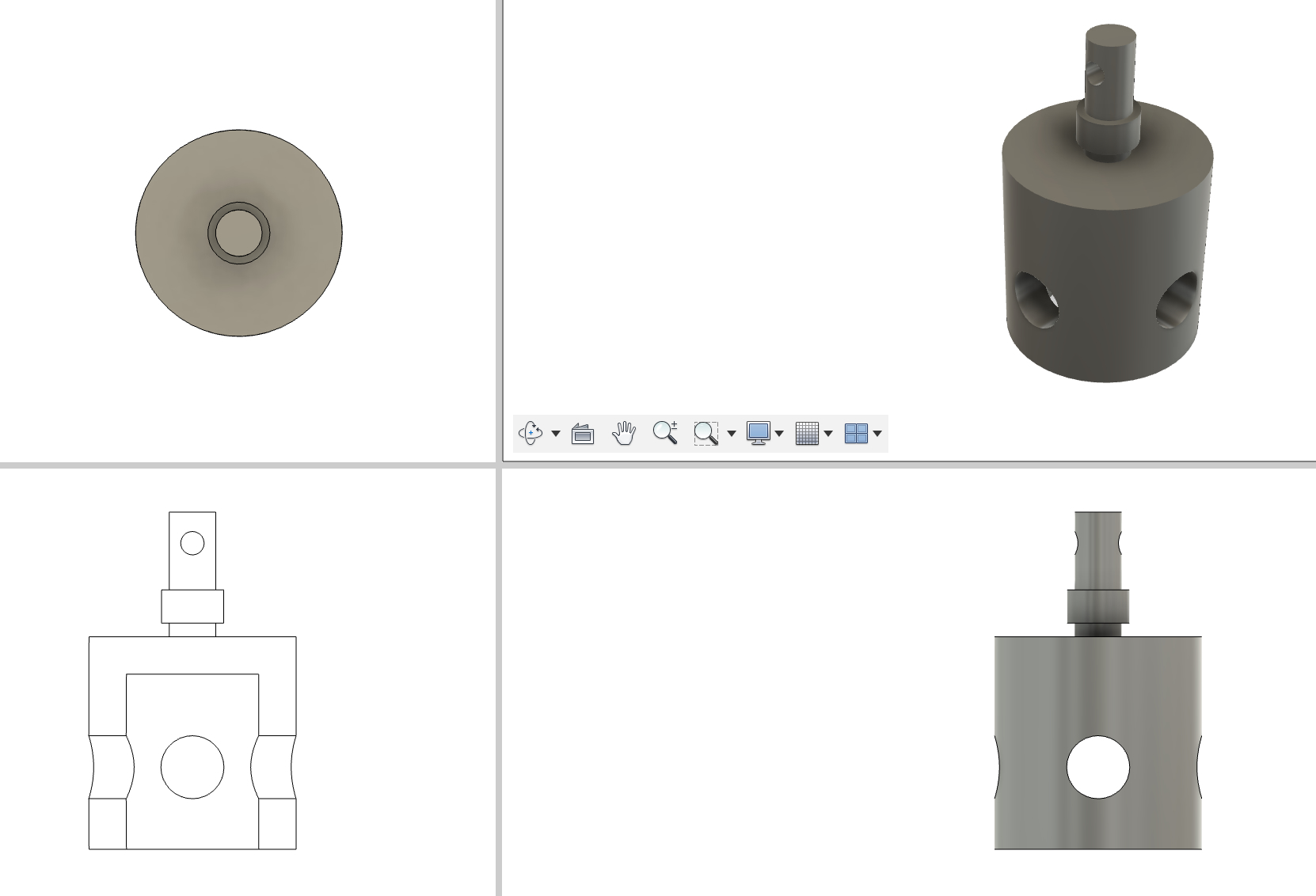
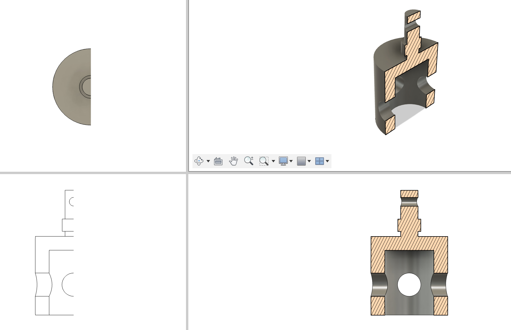
2. Using the Revolve Tool
Instead of extruding multiple parts, I used the Revolve tool to create a complete solid body in one step.
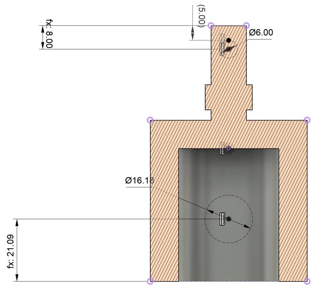
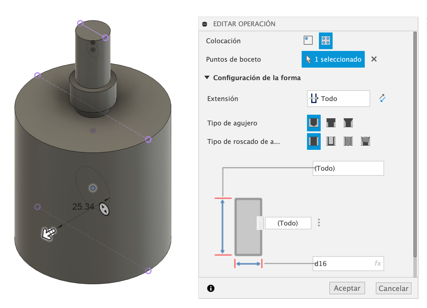
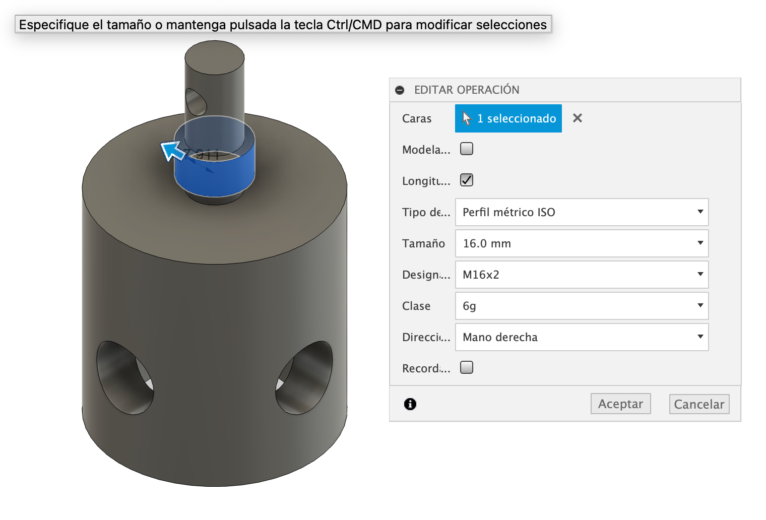
3. Adding Holes and a Thread
Once the base shape was created, I added holes for fasteners using the Hole tool with precise positioning. Then I created a thread for the adjusting Load Cell bolt.
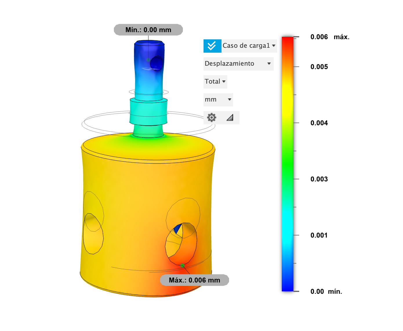
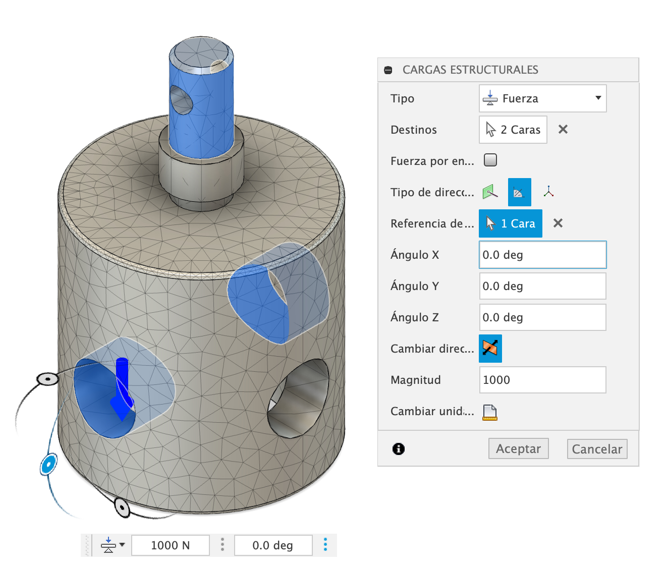
4. Performing a Stress Analysis
A 1kN force was applied to analyze the stress distribution and identify potential weak points in the part.
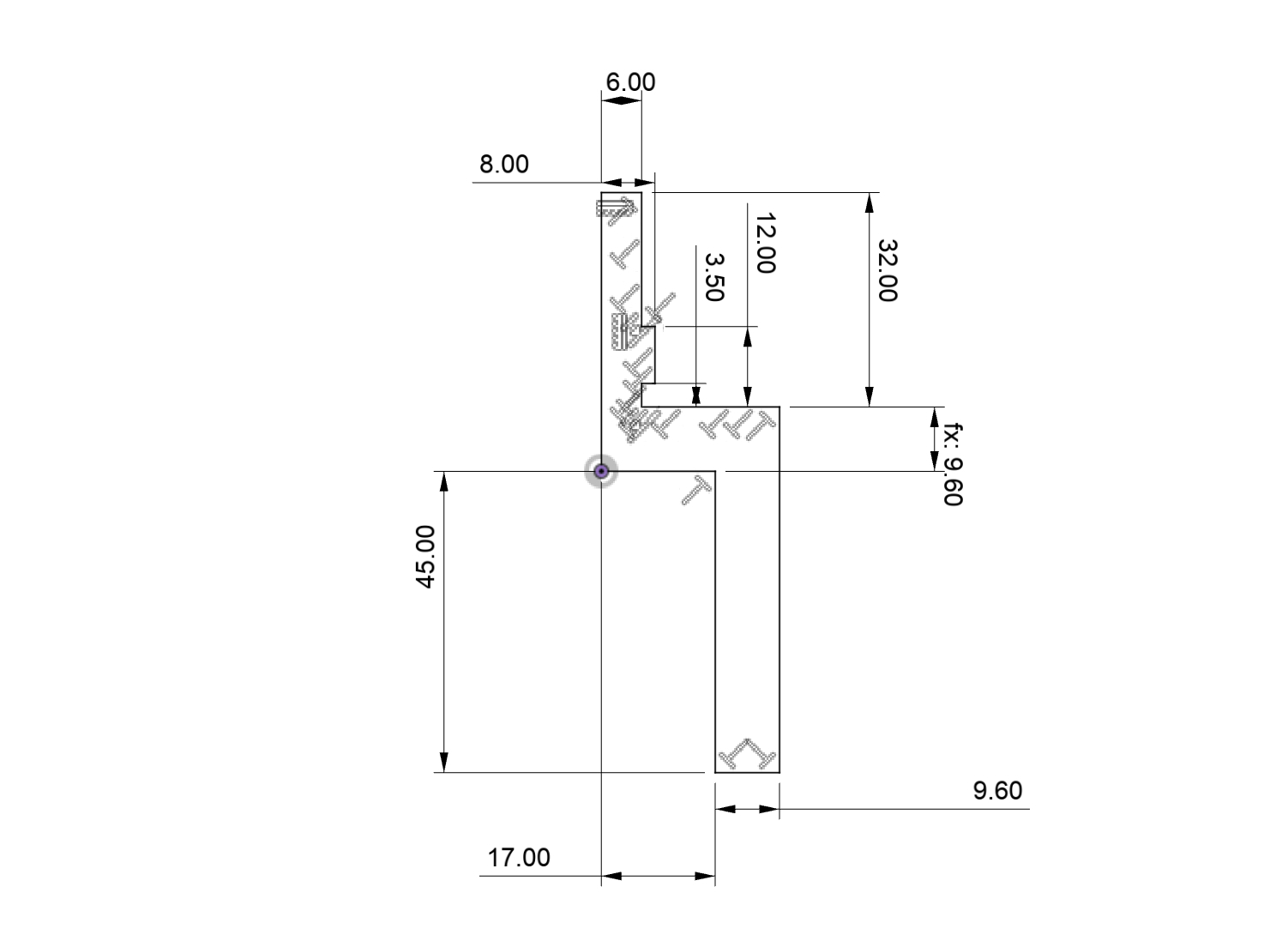
5. Creating a Manufacturing Drawing
Finally, I generated a technical drawing with all dimensions, ready for machining on a conventional lathe.
Download the Fusion 360 File
You can download the Instron Plate / Load Adapter Fusion 360 file here and the drwaing (PDF):
Conclusion
This project successfully demonstrates how Fusion 360 enables rapid design and manufacturing workflows.
- The Revolve tool helped create a solid model in one step.
- Stress analysis confirmed the part can handle a 1kN load.
- Technical drawings allowed for precise machining on a lathe.
Compared to Tinkercad, this workflow is significantly more powerful, efficient, and professional.