Week 14: Interface and application programming
Overview
This week focused on developing and improving User Interfaces (UIs) for microcontroller-based systems. I worked on three different fronts:
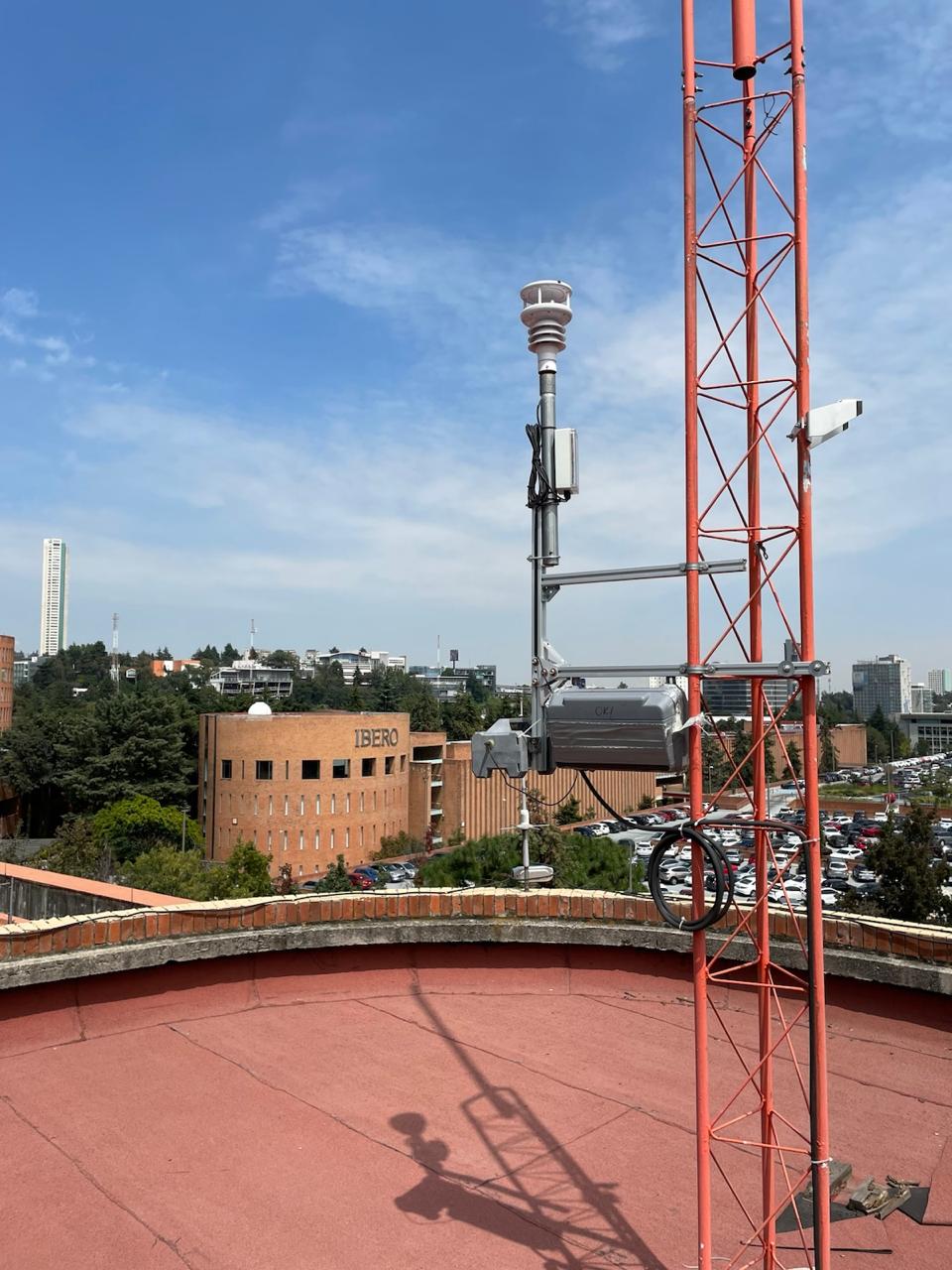
- Weather Station OLED UI: I created a minimalist interface using an ESP32-S3 and a 128x64 OLED screen. This setup connects to a weather station at my lab via a REST API and displays real-time environmental data (solar radiation, temperature, and wind speed).
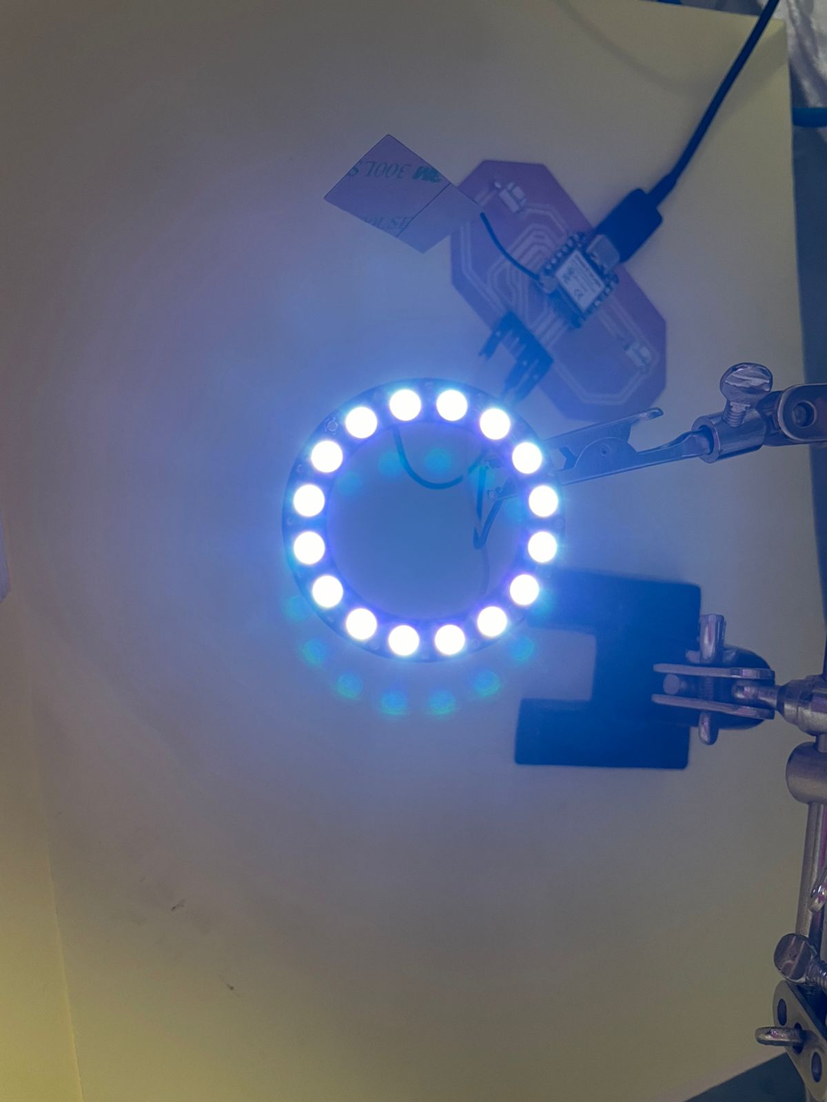
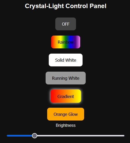
- Crystal Light UI (Improved): I redesigned the web interface used to control a NeoPixel LED ring via Wi-Fi. The updated interface includes animated buttons with visual feedback, a brightness slider, and an OFF button — all embedded directly into the ESP32 as a self-contained web server.
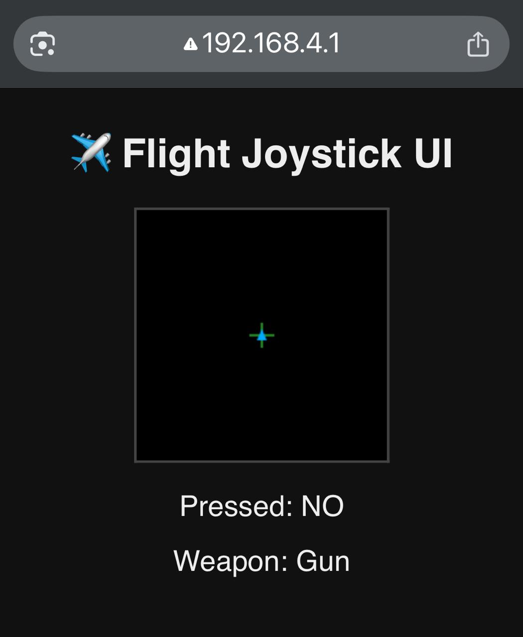
- Joystick-Controlled Plane UI: This one’s wild — using a joystick module connected to an ESP32-S3, I built a real-time plane simulation served directly from the board as a web page. The interface shows a crosshair and a plane that responds to joystick movements. Pressing the stick fires projectiles, and two buttons cycle through weapons (Gun, Missile, Laser, Plasma), each with their own animated effects. It’s basically a browser-based 8-bit dogfight cockpit, all embedded in a microcontroller.
These projects demonstrate different approaches to embedded UI design — local displays (OLED), web-based controls (LED UI), and interactive canvas graphics (Plane UI). They explore trade-offs between minimalism, interactivity, hardware constraints, and creative freedom.
Checklist
- ✅ Linked to the group assignment page
- ✅ Documented your process
- ✅ Explained the UI that you made and how you did it
- ✅ Explained how your application communicates with your embedded microcontroller board
- ✅ Explained any problems you encountered and how you fixed them
- ✅ Included original source code (or a screenshot of the app code if that’s not possible)
- ✅ Included a ‘hero shot’ of your application running & communicating with your board
Group Assignment
During this week we explored different tools that allow microcontrollers to communicate with user-friendly interfaces. The idea was to design a graphical interface that could control or receive data from a board, adding a human touch to our devices. Here are some of the tools we evaluated:
Qt Designer + PyQt
Qt Designer is a GUI design tool for building layouts visually, without writing raw code. Once the layout is ready, it can be converted into Python using PyQt. The interface can send serial commands to the board to control outputs or read data. It’s a powerful stack, especially for desktop applications, but requires installing Python and specific packages.
Processing
Processing is a flexible software sketchbook and a language for learning how to code within the context of the visual arts. It supports serial communication and is ideal for making interactive visuals quickly. However, deploying a Processing sketch requires a computer running it.
App Inventor
MIT App Inventor is a block-based Android app development tool. It allows rapid creation of simple mobile apps that can communicate via Bluetooth or Wi-Fi. While great for mobile use, it introduces complexity in pairing and deployment, especially for non-Android users.
HTML + CSS + JS (My Approach)
I decided to go with a fully embedded interface using just HTML, CSS, and JavaScript hosted directly on the ESP32. This avoids installing external software, works on any device with a browser, and gives me full control over the styling and interaction. The interface lets the user select lighting modes and control brightness, and it all lives directly on the microcontroller.
Comparison Table
| Tool | Platform | Complexity | Needs External Software? |
|---|---|---|---|
| Qt Designer + PyQt | Desktop | High | Yes |
| Processing | Desktop | Medium | Yes |
| App Inventor | Mobile (Android) | Medium | Yes |
| HTML + JS (ESP32) | Browser | Low | No |
Final Decision
Given the need for portability, simplicity, and no dependency on external software, I stuck with an HTML interface embedded directly on the ESP32. It runs on any browser, responds instantly, and makes the project easy to demo without worrying about external tools or setups.
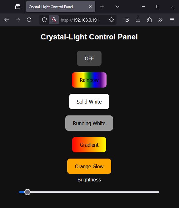
User Interface Upgrade – Crystal-Light Web Controller
In Week 11, I implemented a simple web interface to control a NeoPixel LED ring from an ESP32 board. It was... functional, let's say. This week, I upgraded that interface with a cleaner design, proper feedback when buttons are pressed, and a brightness slider. Below, I document the HTML and JavaScript that make this possible.
Interface Overview
The new interface is hosted directly on the ESP32's web server. It features:
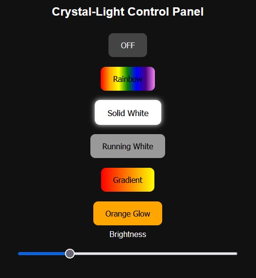
- Six control buttons: OFF, Rainbow, Solid White, Running White, Gradient, and Orange Glow
- A brightness slider
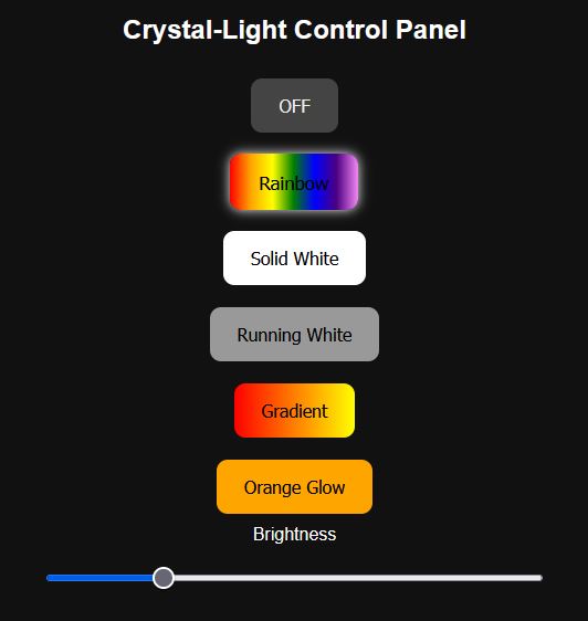
- Visual feedback (glow/animation) when a mode is active
HTML Structure
The HTML sets up the buttons and slider. Each button has a unique ID and class for styling and behavior:
    <button class="btn rainbow" id="btn1" onclick="setEffect(1)">Rainbow</button>
    <input type="range" min="0" max="255" value="100" onchange="setBrightness(this.value)">
CSS Styling
The buttons are styled to reflect the effect they trigger. There's a white glow animation for the active effect (except OFF):
    .btn {
    padding: 15px 25px;
    margin: 10px;
    font-size: 16px;
    border: none;
    border-radius: 10px;
    cursor: pointer;
    transition: all 0.2s;
    }

    .active {
    box-shadow: 0 0 10px #fff;
    transform: scale(1.05);
    }

    .rainbow { background: linear-gradient(to right, red, orange, yellow, green, blue, indigo, violet); color: #000; }
    .white   { background: #fff; color: #000; }
    .run     { background: #999; }
    .gradient{ background: linear-gradient(to right, red, yellow); }
    .orange  { background: orange; }
    .off     { background: #444; color: #eee; }
JavaScript Behavior
The JavaScript fetches commands when a button is clicked, updates which button is active, and sends the brightness value:
    let activeBtn = null;

    function setEffect(effect) {
    fetch(getCmd(effect));
    highlightButton(effect);
    }

    function getCmd(effect) {
    if (effect == 0) return '/off';
    if (effect == 1) return '/rainbow';
    if (effect == 2) return '/solid_white';
    if (effect == 3) return '/running_white';
    if (effect == 4) return '/gradient';
    if (effect == 5) return '/orange_glow';
    }

    function highlightButton(id) {
    if (activeBtn !== null && activeBtn !== 0)
        document.getElementById("btn" + activeBtn).classList.remove("active");

    if (id !== 0)
        document.getElementById("btn" + id).classList.add("active");

    activeBtn = id;
    }

    function setBrightness(val) {
    fetch('/brightness?value=' + val);
    }
Integration with ESP32
This HTML is served directly from the ESP32 using the server.send() function in the Arduino sketch.
When the user clicks a button, the ESP32 receives the command via route handlers like /rainbow or /off,
and updates the LEDs accordingly.
| UI Image | UI Video |
|---|---|
Rainbow light |
|
Solid light |
|
Gradient light |
|

Glow light |
|
|
Brightness control |
|
Minimal OLED UI for Weather Station API
This project uses an ESP32-S3 microcontroller and an I2C OLED display to build a minimal user interface that pulls live data from a weather station API installed at our lab. The idea is to show changing weather conditions like solar radiation, temperature, and wind speed—factors critical for simulating photovoltaic performance in the lab.
WiFi and OLED Initialization
// WiFi credentials
      const char* ssid = "XXxxXXxxxXX";
      const char* password = "XXxxXXxxXX";

      // OLED setup (I2C)
      #define SCREEN_WIDTH 128
      #define SCREEN_HEIGHT 64
      #define OLED_RESET -1
      #define SCREEN_ADDRESS 0x3C

      Adafruit_SSD1306 display(SCREEN_WIDTH, SCREEN_HEIGHT, &Wire, OLED_RESET);

      ...

      Wire.begin(D4, D5); // I2C pins for ESP32-S3
      if (!display.begin(...)) {
        Serial.println("OLED allocation failed");
        for (;;); // halt
      }
This chunk sets up both the OLED screen and WiFi connection. It also includes a check to confirm whether the screen was initialized properly.
Getting Accurate Timestamps
      configTime(-6 * 3600, 0, "pool.ntp.org", "time.nist.gov");

      ...

      time_t now = time(nullptr);
      now -= 120;
      struct tm* startTime = localtime(&now);
      strftime(start, sizeof(start), "%Y-%m-%d %H:%M:%S", startTime);
To get data from the Smability API, you must provide a time range. The ESP32-S3 uses NTP servers to fetch current time, then calculates a 1-minute window (current time minus 120 seconds to current time minus 60) as the API range.
Constructing the API Call
      String url = "http://smability.sidtecmx.com/SmabilityAPI/GetData?token=" + String(token) +
                   "&idSensor=" + String(currentSensor) +
                   "&dtStart=" + encodedStart +
                   "&dtEnd=" + encodedEnd;
This line dynamically builds the API endpoint by injecting the sensor ID, start time, and end time. The URL is properly encoded to handle special characters and spaces.
Fetching & Parsing the Data
      HTTPClient http;
      http.begin(url);
      int httpCode = http.GET();

      if (httpCode > 0) {
        String payload = http.getString();
        StaticJsonDocument<1024> doc;
        deserializeJson(doc, payload);
        float value = doc[0]["Data"];
      }
This is where the magic happens. The ESP32 sends a GET request to the API and parses the JSON response using the ArduinoJson library. The desired data point is extracted from the ["Data"] field of the response array.
Displaying on OLED
      display.clearDisplay();
      display.setTextSize(1);
      display.setCursor(0, 0);
      display.print(sensorLabel);
      display.setTextSize(2);
      display.setCursor(0, 20);
      display.print(value, 1);
      display.setTextSize(1);
      display.setCursor(0, 50);
      display.print(unitLabel);
      display.display();
The OLED is cleared and redrawn for each update. This keeps the UI clean and readable, showing the name of the sensor, a large value, and the units underneath.
Problems and Solutions OLED & Crystal light
While working on the OLED display for the weather station data, I encountered an issue with the API returning HTTP 500 errors. After debugging, I realized the request needed an exact date-time range and the ESP32 clock had not synced correctly with the NTP server. The solution was to add a short delay after configuring NTP and always request data with a safe buffer of two minutes behind the current time.
For the Crystal Light UI, I initially had no visual feedback on which mode was active. I fixed this by adding a glow effect using CSS and highlighting the active button via JavaScript when clicked. Additionally, using `effectChanged` flags in Arduino helped avoid UI lag.
Joystick-Controlled Plane Interface with Weapon Effects
This interface was built as a browser-based cockpit UI using a joystick module (KY-023), an ESP32-S3 board, and a few buttons. It lets the user fly a plane in 2D space, switch weapons, and fire animated projectiles. Everything runs directly in the browser from the ESP32's internal web server.
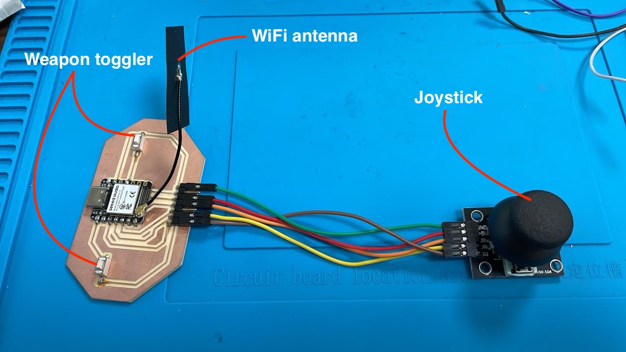
Hardware Setup
The setup consists of:
- A custom PCB with an onboard ESP32-S3 microcontroller (with external antenna)
- Two pushbuttons connected to GPIO0 (D0) and GPIO10 (D10) for weapon switching
- A KY-023 joystick module for directional input and firing
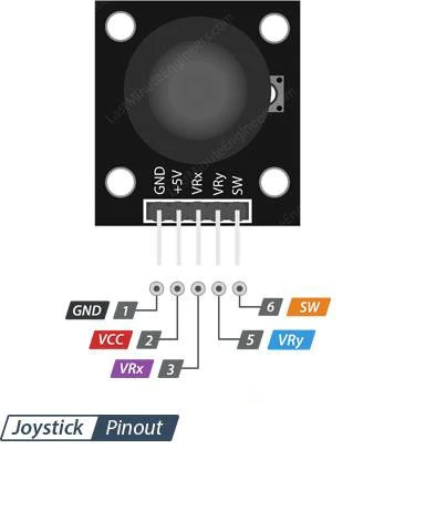
Joystick Pinout
The joystick module exposes five pins. Only three were used:
VRX → GPIO6 (D5)for horizontal movement (X-axis)VRY → GPIO4 (D3)for vertical movement (Y-axis)SW → GPIO2 (D2)for joystick pushbutton (fire)
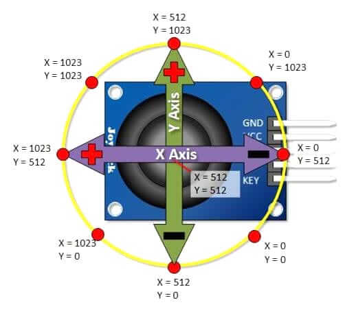
Joystick Calibration
After switching to proper pins, I printed analog values for both axes. When centered, they hovered around:
- X center ≈ 3180
- Y center ≈ 3269
From there, I manually moved the joystick and recorded the min/max values. I adjusted the range to:
const int xMin = 2480;

const int xMax = 3880;
const int yMin = 2569;
const int yMax = 3969;
To deal with jitter and noise from the analog signal, I added two mechanisms:
- Dead zone: if the value is close enough to center (±10), it’s fixed at 50.
- Smoothing: exponential moving average across frames.
// Dead zone

if (abs(xSmooth - 50) < 10) xSmooth = 50;
if (abs(ySmooth - 50) < 10) ySmooth = 50;

// Smoothing
xSmooth = (xSmooth \* 4 + xNorm) / 5;
ySmooth = (ySmooth \* 4 + yNorm) / 5;
Firing and Weapon Switching
The pushbutton built into the joystick triggers a fired flag, with a cooldown delay to avoid spamming projectiles. Two extra buttons control weapon selection. Each weapon has its own projectile limit, color, speed, and size:
const char* weapons[] = {"Gun", "Missile", "Laser", "Plasma"};

if (btnNext == LOW && lastBtnNext == HIGH) {
currentWeapon = (currentWeapon + 1) % numWeapons;
}
Web Interface Code (ESP32-side)
The ESP32 serves an HTML canvas interface and sends joystick data using a REST-like endpoint. This is the JSON output function:
StaticJsonDocument<200> doc;

doc\["x"] = (int)xSmooth;
doc\["y"] = (int)ySmooth;
doc\["pressed"] = isPressed;
doc\["weapon"] = weapons\[currentWeapon];
doc\["fired"] = fired;
serializeJson(doc, response);
server.send(200, "application/json", response);
JavaScript Front-End Highlights
In the HTML interface, the browser polls data every 100ms and uses canvas to update visuals. When fired == true, a new projectile is spawned from the current plane position if cooldown and weapon limits allow:
if (fired && projectiles.length < cfg.max && now - lastFireTime > cfg.cooldown) {

projectiles.push({
x: planeX,
y: planeY,
color: cfg.color,
speed: cfg.speed,
size: cfg.size,
weapon: weapon
});
lastFireTime = now;
}
Weapon Table
| Weapon | Style | Speed | Limit |
|---|---|---|---|
| Gun | Small white dot | 4 | 10 |
| Missile | Orange trail | 2 | 3 |
| Laser | Cyan beam | 6 | 5 |
| Plasma | Glowing orb | 3 | 2 |
Problems I Faced (and Fixes)
- Analog input not responding: I was using D2 (GPIO2) which doesn't support ADC on the ESP32-S3. Fix: switched to D5 and D3.
- Joystick jitter and flicker: The values fluctuated rapidly even when idle. Fix: added a dead zone and smoothing filter in the Arduino code.
- Mobile browser crash: iPhone Chrome would crash due to the constant
<meta refresh>. Fix: switched to JavaScript polling withfetch(). - Only one bullet felt awkward: Originally I only allowed a single projectile. Fix: added projectile array with individual cooldowns and weapon-specific limits.
Full Arduino Code (ESP32-S3)
This is the complete working code for the joystick-controlled plane interface with projectile effects, smoothing, dead zone, and web server:
    #include <WiFi.h>
    #include <WebServer.h>
    #include <ArduinoJson.h>

    #define VRX_PIN D5
    #define VRY_PIN D3
    #define SW_PIN  D2
    #define BTN_NEXT D0
    #define BTN_PREV D10

    WebServer server(80);

    const int xMin = 2480;
    const int xMax = 3880;
    const int yMin = 2569;
    const int yMax = 3969;

    const char* weapons[] = {"Gun", "Missile", "Laser", "Plasma"};
    const int numWeapons = sizeof(weapons) / sizeof(weapons[0]);
    int currentWeapon = 0;
    bool fired = false;

    void handleRoot() {
      String html = R"rawliteral(
      [ ...HTML+JS HERE — TRUNCATED FOR BREVITY... ]
      )rawliteral";
      server.send(200, "text/html", html);
    }

    void handleData() {
      static bool lastBtnNext = HIGH;
      static bool lastBtnPrev = HIGH;
      static unsigned long lastFireTime = 0;
      static float xSmooth = 50;
      static float ySmooth = 50;

      int xVal = analogRead(VRX_PIN);
      int yVal = analogRead(VRY_PIN);
      bool isPressed = digitalRead(SW_PIN) == LOW;
      bool btnNext = digitalRead(BTN_NEXT);
      bool btnPrev = digitalRead(BTN_PREV);

      xVal = constrain(xVal, xMin, xMax);
      yVal = constrain(yVal, yMin, yMax);
      int xNorm = map(xVal, xMin, xMax, 0, 100);
      int yNorm = map(yVal, yMin, yMax, 0, 100);
      xNorm = constrain(xNorm, 0, 100);
      yNorm = constrain(yNorm, 0, 100);

      xSmooth = (xSmooth * 4 + xNorm) / 5;
      ySmooth = (ySmooth * 4 + yNorm) / 5;

      if (abs(xSmooth - 50) < 10) xSmooth = 50;
      if (abs(ySmooth - 50) < 10) ySmooth = 50;

      if (btnNext == LOW && lastBtnNext == HIGH)
        currentWeapon = (currentWeapon + 1) % numWeapons;
      if (btnPrev == LOW && lastBtnPrev == HIGH)
        currentWeapon = (currentWeapon - 1 + numWeapons) % numWeapons;
      lastBtnNext = btnNext;
      lastBtnPrev = btnPrev;

      fired = false;
      if (isPressed && (millis() - lastFireTime > 300)) {
        fired = true;
        lastFireTime = millis();
      }

      StaticJsonDocument<200> doc;
      doc["x"] = (int)xSmooth;
      doc["y"] = (int)ySmooth;
      doc["pressed"] = isPressed;
      doc["weapon"] = weapons[currentWeapon];
      doc["fired"] = fired;

      String response;
      serializeJson(doc, response);
      server.send(200, "application/json", response);
    }

    void setup() {
      Serial.begin(115200);
      pinMode(SW_PIN, INPUT_PULLUP);
      pinMode(BTN_NEXT, INPUT_PULLUP);
      pinMode(BTN_PREV, INPUT_PULLUP);

      WiFi.softAP("JoystickESP", "joystick123");
      delay(1000);
      server.on("/", handleRoot);
      server.on("/data", handleData);
      server.begin();
    }

    void loop() {
      server.handleClient();
    }
Demonstration of plane UI with live joystick input