Week 11: Embedded Networking and Communications
Overview
This week I explored how microcontrollers can talk to each other using both wireless and wired protocols. I set up a network of three custom PCBs, each based on a different Seeed XIAO board: the ESP32C6, ESP32S3, and RP2040. Each board had a unique role and communicated with the others using either Wi-Fi, GPIO, or I2C.
I used HTTP over Wi-Fi to wirelessly control a NeoPixel ring from another board with physical buttons, and GPIO signaling to trigger events like sound or light feedback from a third board. I also integrated visual feedback through a 16x2 LCD screen using the I2C protocol on the ESP32S3 — connected via SDA and SCL. Additionally, a soil moisture sensor was connected to the RP2040, which detected "wet" or "dry" states and transmitted this data to the ESP32C6 via a wired connection.
Each of these boards was embedded in a custom-designed and milled PCB. The design and fabrication process was completed during Week 8: Electronics Production, and reused here to showcase real-world embedded communication.
Through this networked setup, I understood the trade-offs between protocols, the importance of voltage and pin configuration, and the joy of making things blink, beep, display sarcastic messages, or smile when the soil is moist enough.
Checklist
- ✅ Linked to the group assignment page
- ✅ Documented power consumption of the output device
- ✅ Documented what I learned from interfacing output devices
- ✅ Linked to the board I made previously
- ✅ Explained the programming process I used
- ✅ Explained problems I encountered and how I fixed them
- ✅ Included original source code and any new design files
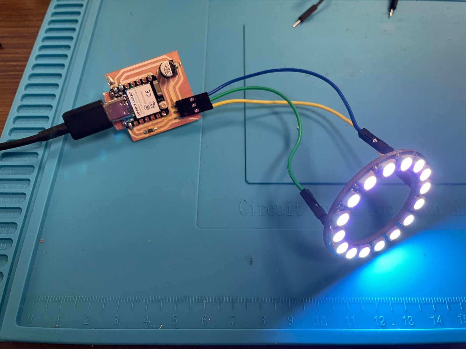
- ✅ Included a ‘hero shot’ of my board
Group Assignment
As a group, we explored and tested several wired communication protocols between development boards, specifically UART, I2C, and SPI. Each team member contributed by wiring different microcontrollers, sending messages, and debugging signal transmission using serial terminals and oscilloscopes.
The testing was done in pairs or small teams and focused on point-to-point and master-slave communication using various board combinations. The results are documented on the Puebla lab's Week 11 page.
Communication Protocol Comparison
| Protocol | Type | Wiring | Speed | Use Case |
|---|---|---|---|---|
| UART | Serial (point-to-point) | TX/RX + GND | Medium | Simple device-to-device messaging |
| I2C | Serial (multi-master/slave) | SDA/SCL + GND | Medium | Sensors, LCDs, displays |
| SPI | Serial (master/slaves) | MOSI/MISO/SCK/SS | High | Fast data transfer with multiple devices |
Observations and Notes
- UART: Easy to use and works well for simple setups, but it's strictly one-to-one. No addressing.
- I2C: Great for many low-speed devices on the same two wires. Needs attention to addressing and pull-ups.
- SPI: Fast and powerful, but the wiring complexity increases rapidly with more devices.
My Takeaways
While our group focused entirely on wired communication, in my individual assignment I also tested wireless networking using Wi-Fi and HTTP. This let me control remote lighting effects and opened up possibilities for IoT-style interactions.
Additionally, I used I2C for local communication between my ESP32S3 and a 16x2 LCD display, wired through SDA and SCL. This gave useful visual feedback and reminded me to double-check voltage lines (spoiler: 3.3V won’t cut it for every screen).
ESP32C6 as Webserver for NeoPixel Ring
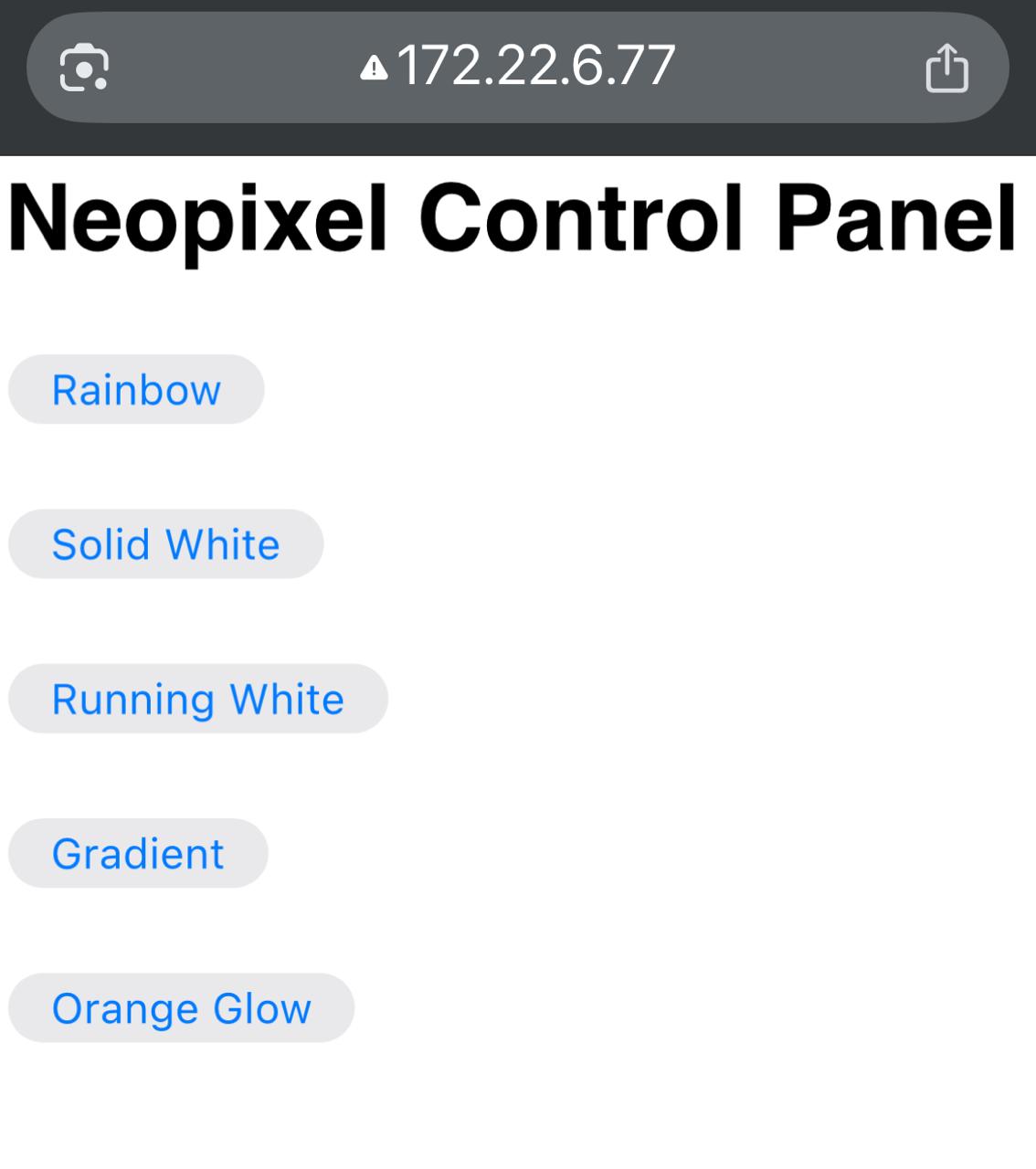
As part of the networking and communications week, I set up my ESP32C6 as a standalone web server that hosts a control panel for a NeoPixel LED ring. It allows users to trigger different light effects wirelessly through a web interface served directly by the microcontroller.
The ESP32C6 acts as a Wi-Fi client, connects to an existing network, and exposes a series of endpoints like rainbow, solid_white, etc., that trigger different lighting effects. The web interface includes buttons for each mode.
Code for ESP32C6 Webserver
      #include <WiFi.h>
      #include <Adafruit_NeoPixel.h>
      #include <WebServer.h>

      #define LED_PIN D0
      #define NUM_LEDS 16
      #define BRIGHTNESS 100

      const char* ssid = "XXXxxXXxx";
      const char* password = "XXXxxXXXXx";

      Adafruit_NeoPixel strip(NUM_LEDS, LED_PIN, NEO_GRB + NEO_KHZ800);
      WebServer server(80);

      int currentEffect = 0;
      bool effectChanged = false;

      void setup() {
        Serial.begin(115200);
        WiFi.begin(ssid, password);
        while (WiFi.status() != WL_CONNECTED) delay(500);

        strip.begin();
        strip.setBrightness(BRIGHTNESS);
        strip.clear();
        strip.show();

        server.on("/", handleRoot);
        server.on("/rainbow", [](){ currentEffect = 1; effectChanged = true; server.send(200, "text/plain", "Rainbow Mode ON"); });
        server.on("/solid_white", [](){ currentEffect = 2; effectChanged = true; server.send(200, "text/plain", "Solid White ON"); });
        server.on("/running_white", [](){ currentEffect = 3; effectChanged = true; server.send(200, "text/plain", "Running White LED ON"); });
        server.on("/gradient", [](){ currentEffect = 4; effectChanged = true; server.send(200, "text/plain", "Gradient Effect ON"); });
        server.on("/orange_glow", [](){ currentEffect = 5; effectChanged = true; server.send(200, "text/plain", "Orange Glow Mode ON"); });
        server.begin();
      }
Code Breakdown – ESP32C6 Webserver
Below is an explanation of how the code for my ESP32C6 webserver works. Each section is grouped by function, with beginner-friendly descriptions of what each chunk does and how it contributes to building a wireless LED controller.
1. Libraries and Setup
#include <WiFi.h> – Enables Wi-Fi functions on the ESP32
#include <Adafruit_NeoPixel.h> – Lets us control the NeoPixel LED ring
#include <WebServer.h> – Turns the ESP32 into a basic web server that can respond to browser requests
2. Pin Definitions and Wi-Fi Credentials
We define the pin where the NeoPixel ring is connected (D0), how many LEDs it has, and how bright they should be. The ssid and password store the login info for your Wi-Fi network.
3. Creating the LED Strip and Web Server
We create a strip object to control the NeoPixels, and a server object listening on port 80 (the default for web browsers). We also create two variables: currentEffect to store the selected lighting mode, and effectChanged to detect changes.
4. Connecting to Wi-Fi
The board attempts to connect to the specified Wi-Fi network. While it waits, it prints dots to the serial monitor. Once connected, it prints the assigned IP address so we can access the web server from a browser.
5. Initializing the LED Ring
The LED ring is set up: brightness is applied, all LEDs are turned off using clear(), and changes are shown with show().
6. Defining Web Routes
Each route is a different webpage path like /rainbow or /solid_white. These trigger lighting effects. The root path / shows a webpage with clickable buttons. When a button is clicked, the server changes the lighting mode.
7. Main Loop
The loop() function constantly checks for browser input via server.handleClient(). Based on which effect is active, it runs the appropriate function to generate the LED animation. If a new effect is selected, the current one stops cleanly.
8. Light Effect Functions
Each animation (rainbow, solid white, running white, gradient, orange glow) is coded separately for better organization. All of them include server.handleClient() to keep the web server responsive during animations.
In Short:
- The ESP32C6 connects to Wi-Fi.
- It hosts a small web page with buttons for controlling the LED ring.
- Each button click triggers a new lighting mode.
- Animations run smoothly and can be interrupted when a new effect is selected.
Web Interface and Light Effects
Once the webserver is running, this part of the code handles two key things:
- Loop Function: Keeps checking for button presses via HTTP requests.
- UI Interface: A simple HTML page that allows the user to control the lights using buttons.
Web Interface Setup
void handleRoot() {
          server.send(200, "text/html",
            "<html><body style='font-family:sans-serif;'>"
            "<h2>Neopixel Control Panel</h2>"
            "<button onclick=\"fetch('/rainbow')\">Rainbow</button><br><br>"
            "<button onclick=\"fetch('/solid_white')\">Solid White</button><br><br>"
            "<button onclick=\"fetch('/running_white')\">Running White</button><br><br>"
            "<button onclick=\"fetch('/gradient')\">Gradient</button><br><br>"
            "<button onclick=\"fetch('/orange_glow')\">Orange Glow</button>"
            "</body></html>");
        }
This function builds a basic webpage with buttons. When a button is clicked, it sends a request to the ESP32 to change the light mode. The page is clean and simple — no external libraries, just raw HTML and JavaScript fetch().
Rainbow Mode
void rainbowCycle(int wait) {
          for (int j = 0; j < 256 && currentEffect == 1; j++) {
            for (int i = 0; i < NUM_LEDS; i++) {
              strip.setPixelColor(i, Wheel((i * 256 / NUM_LEDS + j) & 255));
            }
            strip.show();
            delay(wait);
            server.handleClient();
          }
        }
Cycles through rainbow colors by shifting hues across the LED ring. Gives a colorful dynamic effect — great for showing off addressable LEDs.
Solid White
void solidWhite() {
          strip.fill(strip.Color(255, 255, 255));
          strip.show();
          while (currentEffect == 2) server.handleClient();
        }
All LEDs are set to white and stay that way until another effect is triggered. Clean and minimal.
Running White
void runningWhite() {
          while (currentEffect == 3) {
            for (int i = 0; i < NUM_LEDS; i++) {
              strip.clear();
              strip.setPixelColor(i, strip.Color(255, 255, 255));
              strip.show();
              delay(100);
              server.handleClient();
              if (effectChanged) { effectChanged = false; return; }
            }
          }
        }
A single white light travels around the ring like a chasing light. Resets each loop.
Gradient Run
void gradientRun() {
          strip.clear();
          for (int i = 0; i < NUM_LEDS && currentEffect == 4; i++) {
            float ratio = (float)i / (NUM_LEDS - 1);
            int r = 255;
            int g = int(255 * ratio);
            int b = 0;
            strip.setPixelColor(i, strip.Color(r, g, b));
            strip.show();
            delay(100);
            server.handleClient();
            if (effectChanged) { effectChanged = false; return; }
          }
        }
LEDs gradually shift from red to yellow across the ring, leaving a solid trail behind. Simple but elegant transition.
Orange Glow
void orangeGlow() {
          while (currentEffect == 5) {
            float level = (sin(millis() / 1000.0 * PI) + 1) / 2;
            int brightness = 30 + int(level * 100);
            for (int i = 0; i < NUM_LEDS; i++) {
              strip.setPixelColor(i, strip.Color(brightness, brightness / 2, 0));
            }
            strip.show();
            delay(30);
            server.handleClient();
            if (effectChanged) { effectChanged = false; return; }
          }
        }
Creates a smooth pulsing orange effect, simulating a glow like firelight. Uses a sine wave to change brightness gradually.
Lessons Learned
- It's important to keep
server.handleClient()in all animation loops to maintain responsiveness. - Adafruit NeoPixel and WebServer libraries work well together but timing-sensitive effects can block communication if not handled carefully.
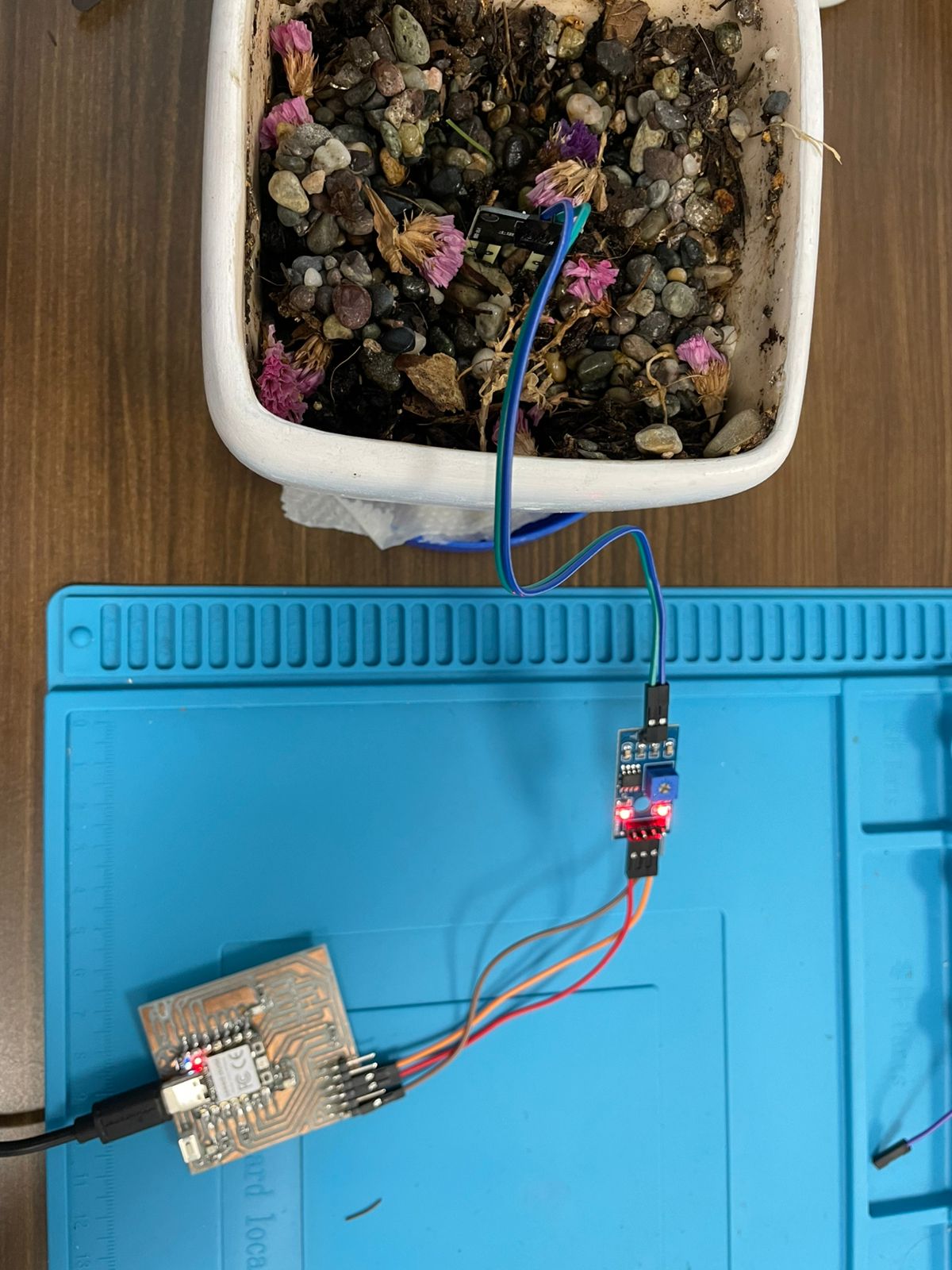
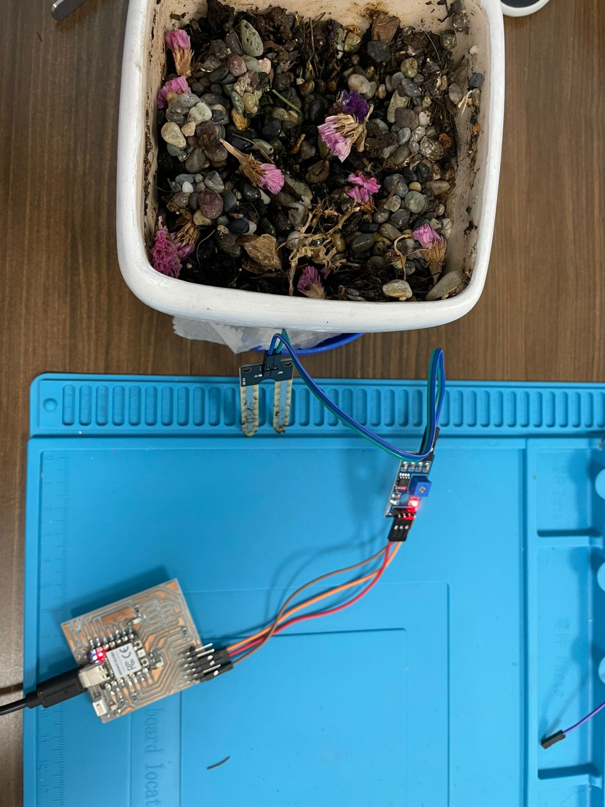
Final Setup and Role of Each Board
At the end of this week's assignment, I built a simple but functional embedded network using three different microcontrollers, each embedded in its own custom PCB:
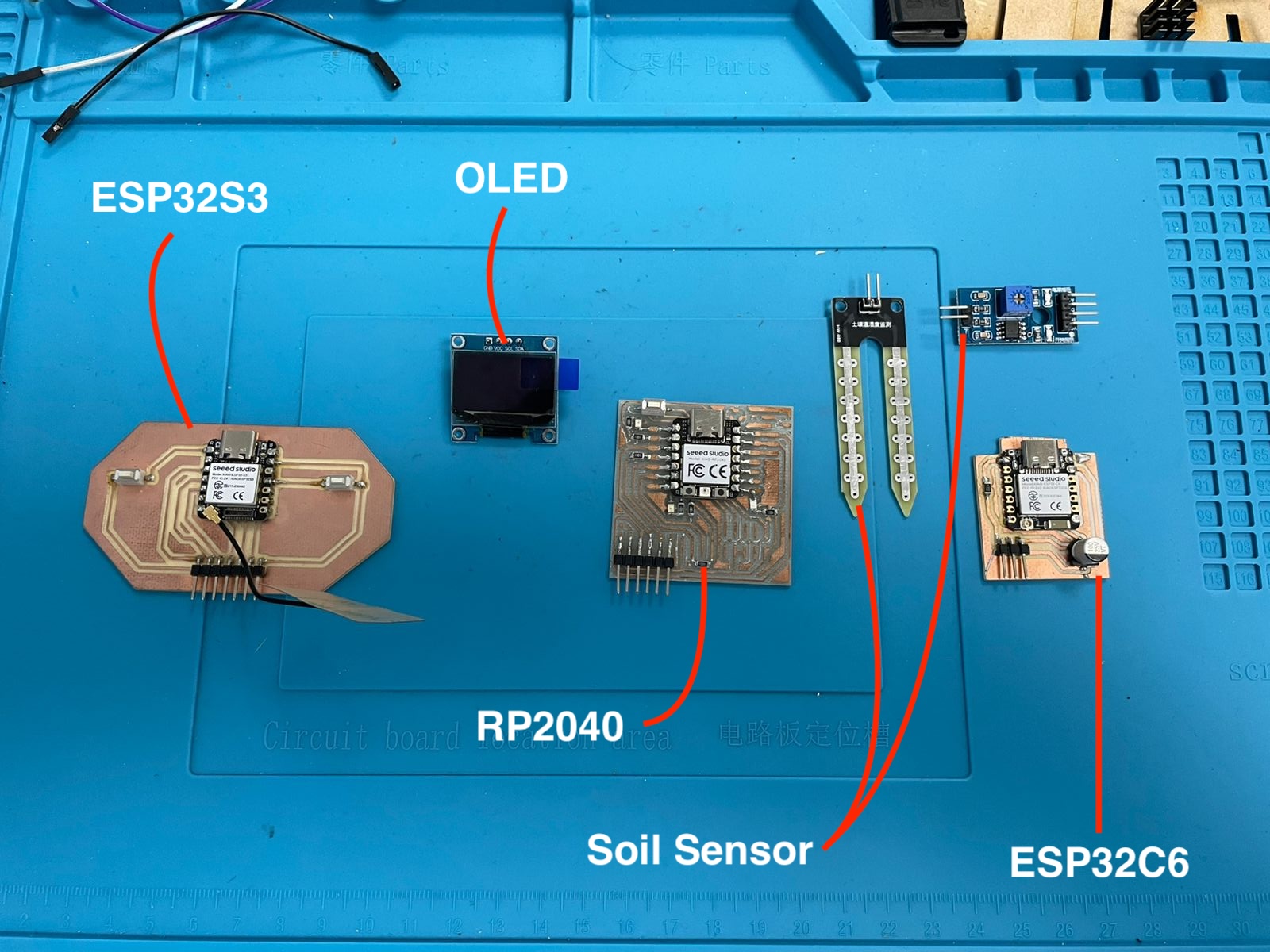
XIAO RP2040 (Sensor Node): This board was responsible for reading soil moisture levels using an FC-28 digital sensor. It was calibrated using the onboard potentiometer and sent a HIGH or LOW signal based on soil humidity. The signal output was routed via a digital pin to the next node.
XIAO ESP32C6 (Central Node / Web Server): This board acted as the central hub of the system. It received the soil moisture signal via a physical wire from the RP2040 and hosted a local Wi-Fi network and web server. The status of the soil (wet or dry) could be checked on any mobile device connected to the network through a simple web interface.
XIAO ESP32S3 (Interface Node): This board connected wirelessly to the ESP32C6’s network. It displayed the soil condition on a 16x2 LCD screen via I2C (SDA/SCL lines), using smiley or sad faces to indicate moisture levels. It also had two pushbuttons on pins D0 and D10 available for future interaction or extension of the system.
Together, this network allowed for distributed sensing (RP2040), central decision-making and broadcasting (ESP32C6), and human-readable feedback (ESP32S3). Each board had a distinct role, minimal wiring, and leveraged different communication protocols (GPIO, HTTP, I2C), showcasing how embedded systems can cooperate in simple environmental sensing tasks.
FC-28 Soil Moisture Sensor
The FC-28 is a basic analog and digital soil moisture sensor used to detect water levels in soil. It uses two exposed probes to pass current through the soil, measuring the resistance to estimate moisture content.
The module includes a small onboard comparator board with a potentiometer that allows you to set a threshold. When the soil is dry, the resistance is high; when the soil is wet, the resistance is low. This sensor can output either:
- Analog signal (A0): Proportional to moisture level
- Digital signal (D0): HIGH or LOW based on the threshold set by the potentiometer
In this project, we used the digital pin (D0) to detect dry or wet states and connected it to the D2 pin of the RP2040.
Pinout
- VCC: 3.3V or 5V power supply
- GND: Ground
- A0: Analog output (not used in this project)
- D0: Digital output (connected to RP2040 D2)
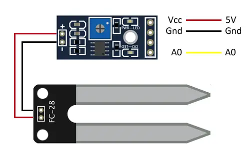
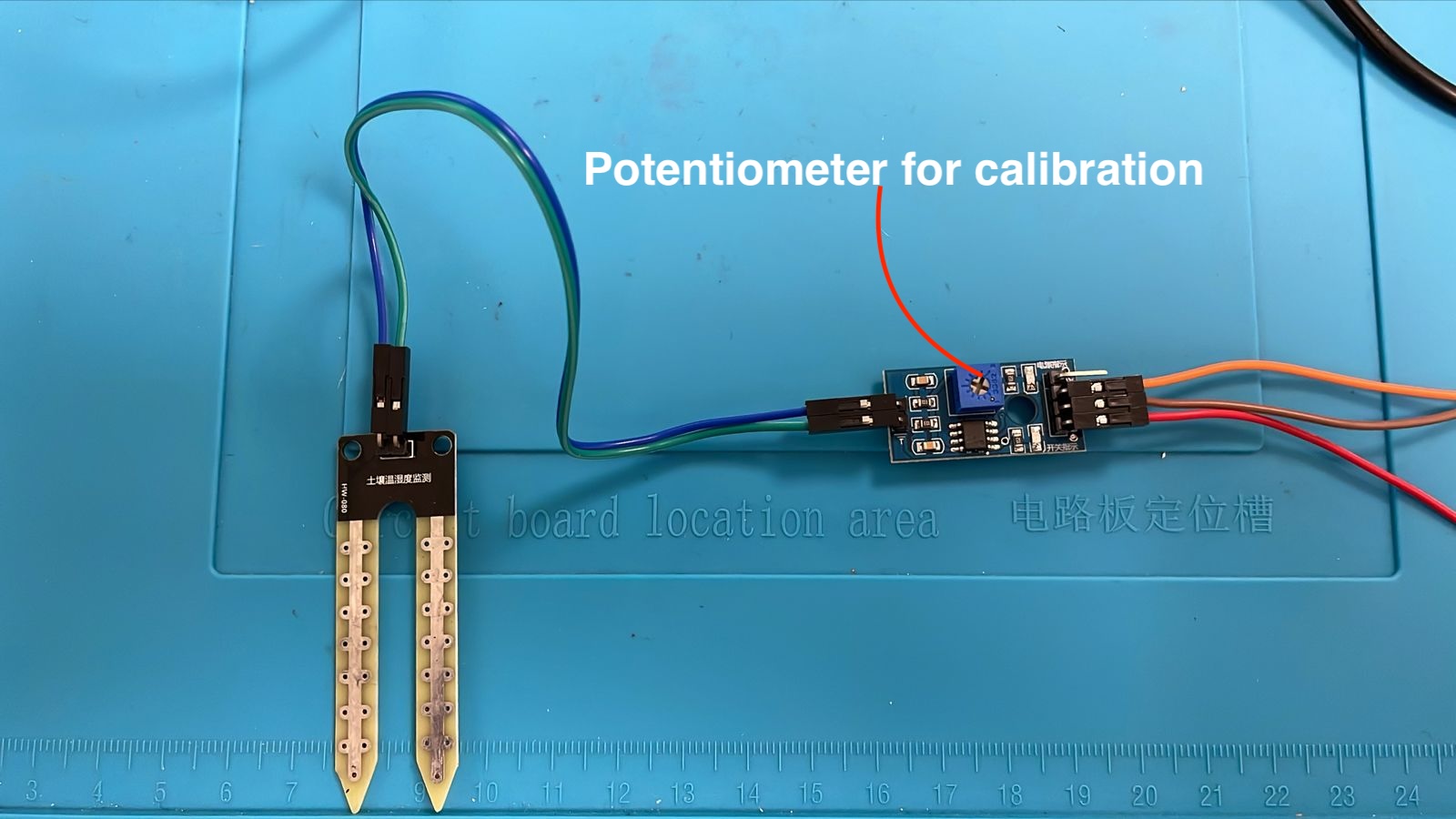
The potentiometer on the small onboard PCB was adjusted to fine-tune the threshold for when the sensor should report the soil as "dry." This was done manually during the setup and calibration stage. See the RP2040 section for more info.
RP2040
The RP2040 board reads a soil moisture sensor (FC-28) connected to pin D2. We calibrated the sensor by adjusting the onboard potentiometer while monitoring the status LED and serial output. Below is the initial setup code for calibration:
// Calibration Code

      \#define SENSOR\_PIN D2

      void setup() {
      Serial.begin(115200);
      pinMode(SENSOR\_PIN, INPUT);
      }

      void loop() {
      int state = digitalRead(SENSOR\_PIN);
      Serial.println(state ? "WET" : "DRY");
      delay(500);
      }
After confirming proper readings and tuning the sensitivity, we connected the output pin D3 to the ESP32C6. The final code simply reads the sensor and reflects its state on an output pin:
// Final Code to send data to ESP32C6
\#define SENSOR\_PIN D2
\#define OUTPUT\_PIN D3
void setup() {
pinMode(SENSOR\_PIN, INPUT);
pinMode(OUTPUT\_PIN, OUTPUT);
}
void loop() {
bool isWet = digitalRead(SENSOR\_PIN);
digitalWrite(OUTPUT\_PIN, isWet ? HIGH : LOW);
delay(1000);
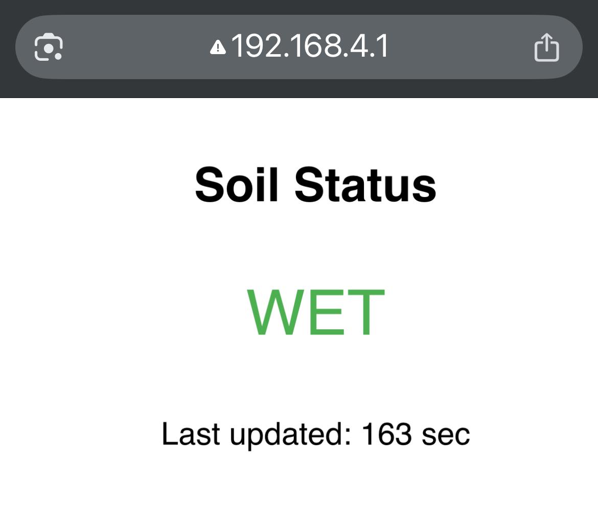
}ESP32C6: Local Web Server and Data Hub
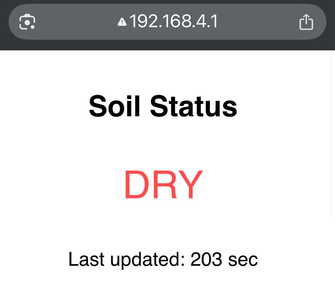
This ESP32C6 board acts as the central node and creates a local Wi-Fi access point using WiFi.softAP(). It doesn’t rely on an external network — devices like a phone or laptop can connect directly to it. Once connected, users can access a simple web page showing the soil moisture status ("WET" or "DRY"), based on the signal it receives through a physical GPIO connection from the RP2040.
    #include <WiFi.h>
    #include <WebServer.h>

    #define INPUT_PIN D0

    WebServer server(80);
    String soilState = "WET";
    unsigned long lastDryPulse = 0;
    unsigned long dryTimeout = 10000;  // 10 seconds to auto-revert to WET

    void setup() {
      pinMode(INPUT_PIN, INPUT);
      Serial.begin(115200);

      WiFi.softAP("SoilMonitor", "12345678");
      delay(1000);

      Serial.println("ESP32C6 Access Point ready");
      Serial.print("IP: ");
      Serial.println(WiFi.softAPIP());

      server.on("/", handleRoot);
      server.on("/soil", handleSoilState);
      server.begin();
    }

    void loop() {
      server.handleClient();

      if (digitalRead(INPUT_PIN) == HIGH) {
        if (soilState != "DRY") {
          Serial.println("Soil is DRY (pulse received)");
        }
        soilState = "DRY";
        lastDryPulse = millis();
        delay(500);  // debounce
      }

      // Auto-reset to WET if no pulse in X seconds
      if (soilState == "DRY" && millis() - lastDryPulse > dryTimeout) {
        Serial.println("No DRY pulse received recently — assuming WET");
        soilState = "WET";
      }
    }

    void handleRoot() {
      String color = soilState == "DRY" ? "#ff4d4d" : "#4CAF50";

      String html = "<html><head><title>Soil Monitor</title>"
                    "<meta http-equiv='refresh' content='10'>"
                    "<style>body{font-family:sans-serif;text-align:center;padding:2em;}"
                    ".status{font-size:2em;color:" + color + ";}</style></head><body>"
                    "<h2>Soil Status</h2>"
                    "<p class='status'>" + soilState + "</p>"
                    "<p>Last updated: " + String(millis() / 1000) + " sec</p>"
                    "</body></html>";

      server.send(200, "text/html", html);
    }

    void handleSoilState() {
      server.send(200, "text/plain", soilState);
    }
How it works:
- WiFi.softAP() starts a local Wi-Fi network named
SoilMonitorwith the password12345678. - The root path
/serves an auto-refreshing HTML page that displays the soil status in red or green depending on the last signal received. - If no "DRY" signal is received for 10 seconds, the system assumes the soil is WET again — a form of auto-reset safety.
- The secondary route
/soilreturns a simple "WET" or "DRY" string in plain text for future integrations or debugging.
ESP32S3: OLED Wireless Display
This board connects wirelessly to the ESP32C6 access point to retrieve soil moisture data. It uses a 128x64 OLED display over I2C to show a happy face if the soil is wet, and a sad face if it is dry. It pulls data via HTTP using the WiFiClient and HTTPClient libraries.
OLED Wiring (I2C)
- VCC → 5V
- GND → GND
- SDA → D4
- SCL → D5
  #include <WiFi.h>
  #include <HTTPClient.h>
  #include <Wire.h>
  #include <Adafruit_GFX.h>
  #include <Adafruit_SSD1306.h>

  #define SCREEN_WIDTH 128
  #define SCREEN_HEIGHT 64
  #define OLED_RESET -1
  #define SCREEN_ADDRESS 0x3C

  #define SDA_PIN D4
  #define SCL_PIN D5

  const char* ssid = "SoilMonitor";
  const char* password = "12345678";

  Adafruit_SSD1306 display(SCREEN_WIDTH, SCREEN_HEIGHT, &Wire, OLED_RESET);

  void setup() {
    Serial.begin(115200);
    Wire.begin(SDA_PIN, SCL_PIN);

    if (!display.begin(SSD1306_SWITCHCAPVCC, SCREEN_ADDRESS)) {
      Serial.println("OLED not found");
      while (true);
    }

    display.clearDisplay();
    display.setTextSize(1);
    display.setTextColor(WHITE);
    display.setCursor(0, 0);
    display.println("Connecting to WiFi...");
    display.display();

    WiFi.begin(ssid, password);
    while (WiFi.status() != WL_CONNECTED) {
      delay(500);
      Serial.print(".");
    }

    display.clearDisplay();
    display.setCursor(0, 0);
    display.println("WiFi Connected!");
    display.display();
  }

  void loop() {
    if (WiFi.status() == WL_CONNECTED) {
      HTTPClient http;
      http.begin("http://192.168.4.1/soil");
      int httpCode = http.GET();

      if (httpCode == 200) {
        String payload = http.getString();
        display.clearDisplay();
        display.setTextSize(2);
        display.setCursor(0, 0);

        if (payload == "WET") {
          display.println("Soil: WET");
          display.setTextSize(3);
          display.setCursor(32, 32);
          display.println(":)");
        } else {
          display.println("Soil: DRY");
          display.setTextSize(3);
          display.setCursor(32, 32);
          display.println(":(");
        }
        display.display();
      }
      http.end();
    }
    delay(5000); // update every 5 sec
  }
Explanation
The ESP32S3 connects to the ESP32C6's softAP WiFi network called "SoilMonitor". Every 5 seconds, it sends an HTTP GET request to http://192.168.4.1/soil to retrieve the current soil status. Depending on the response ("WET" or "DRY"), it displays a corresponding message and emoticon on the OLED screen.
System Recap
This setup completes a three-board embedded network:
- RP2040: Measures soil moisture and sends a HIGH signal via D3 to the ESP32C6 when the soil is dry.
- ESP32C6: Acts as a softAP and simple web server. Receives GPIO signal from RP2040 and serves soil status over Wi-Fi.
- ESP32S3: Connects via Wi-Fi to the ESP32C6 and displays soil status on an OLED screen using I2C.
This network demonstrates successful implementation of both wired GPIO signaling and wireless HTTP communication, integrating a soil moisture sensor and a visual OLED display for feedback.