Networking and communications
Throughout this week will address the issue of Embedded Networking and Communications, in this week as throughout the FabAcademy, there are two assignments one group and one individual.
For group assignment you need to do these activities: send a message between two projects and document your work on the group work page and reflect on your individual page what you have learned
Finally, the individual assignment must comply with the following design point, build and connect wired or wireless node(s) with network or bus addresses and a local interface.
Group assignment week 4
what is Networking and communications?
Networking and communications refer to the technologies and processes involved in connecting computers, devices, and systems to enable them to communicate and share resources with each other. This encompasses various methods and protocols for transmitting data, such as wired and wireless connections, internet protocols, and networking hardware.
SPI
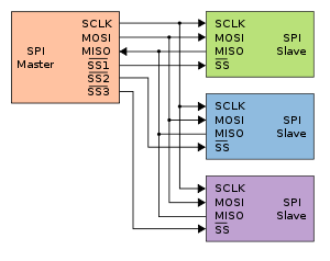
The Serial Peripheral Interface (SPI) is a synchronous serial communication interface commonly used in embedded systems, microcontrollers, and peripheral devices to facilitate communication between them.
- SCLK (Serial Clock): The clock signal generated by the master device to synchronize data transmission.
- MOSI (Master Out Serial In): The data line through which the master sends data to the slave device.
- MISO (Master In Serial Out): The data line through which the slave sends data to the master device.
- SS/CS (Slave Select/Chip Select): The signal used by the master device to select the slave device with which it wants to communicate.
UART
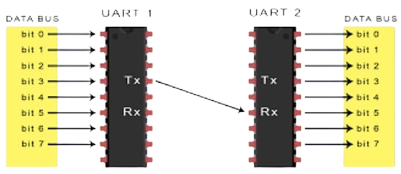
UART, or Universal Asynchronous Receiver/Transmitter, is a fundamental component in electronic communication, enabling the exchange of data between devices in a wide range of applications. This communication method is particularly valuable in scenarios where direct, point-to-point connections are required, such as between microcontrollers, sensors, and peripheral devices.
- Transmitter (TX): The UART transmitter converts parallel data from the device into a serial data stream for transmission. It sends out data one bit at a time, starting with the least significant bit (LSB) and ending with the most significant bit (MSB).
- Receiver (RX): The UART receiver converts the incoming serial data stream back into parallel data for use by the device. It synchronizes with the incoming data based on the agreed-upon baud rate and other settings.
I2C
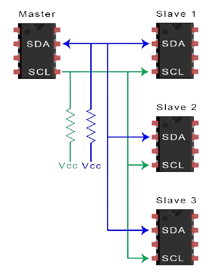
Is a serial communication protocol for two-wire (two-wire) which is used to connect two low-speed devices (low-speed) such as microcontrollers, ADC, DAC, EEPROM. Invented by semiconductor company Philips, widely used by most IC manufacturers Easy to use Can connect as many devices as possible Each I2C slave device requires an address obtained from NXP (the replacement company for Philips Semiconductors)
- SCL (Serial Clock Line): Controlled by the master device, it synchronizes the data transfer between devices on the I2C bus.
- SDA (Serial Data Line): Used for sending and receiving data between the master and the slave. Both lines are bidirectional.
- Master and Slave Devices: Any device can function as master or slave. Masters control the clock line and initiate communication with slaves.
What would it do?
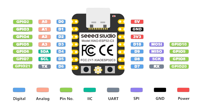
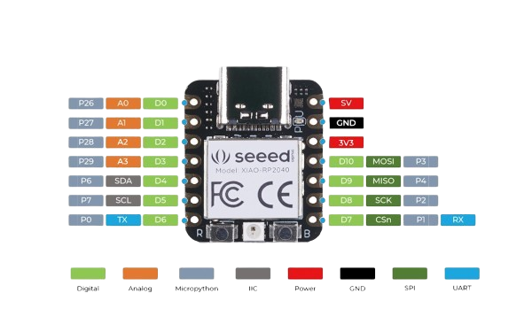
For this signation I will be using three boards, the first board is a XIAO RP2040 (Quentorres), a XIAO ESP32C3 and an Arduino UNO. The XIAO ESP32C3 is the same that I'll be using for my final project
 (1) (1).jpg)
For this task, I will be communicating between the boards using I2C communication. I chose this method because it uses the fewest wires when more than two boards are required. If there were only two boards, I probably would have used UART communication.
Since I will be using I2C communication, I will need a master and a slave. I decided that the master will be the Arduino UNO, and the two XIAO boards will be my slaves. Below, I will explain what each board will do.
Arduino UNO
I decided that my Arduino UNO will be the master because it is the most suitable for performing a simple task and sending instructions to the slaves. The action that this Arduino UNO will perform is to turn the built-in LED on and off while sending a signal, with a 3-second delay before turning the LED on again.
.png)
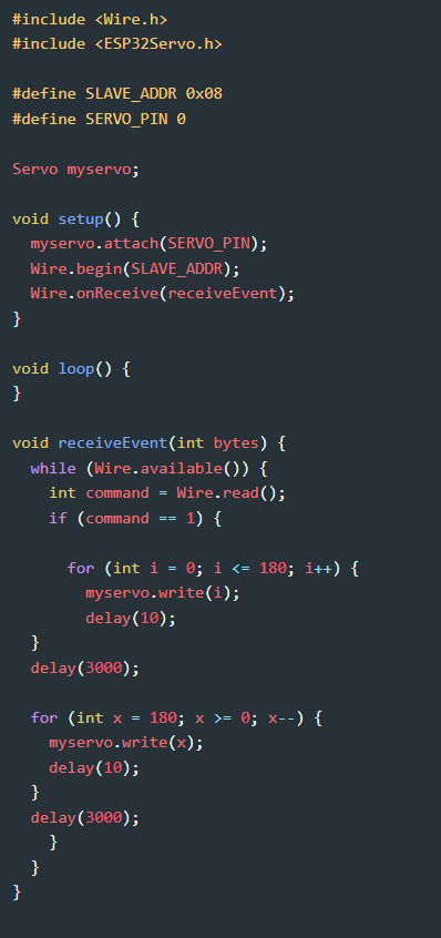
XIAO ESP32C3
What this board will do is, upon receiving the signal from the Arduino, move a servomotor to oscillate between its origin point (0°) and 180°. When it reaches its final point (180°), it will return to the origin (0°), continuing this oscillation as long as it receives the signal from the Arduino.
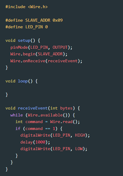
XIAO RP2040
This last board (Quentorres) will receive the signal and will turn a LED connected to pin D0 on and off, with a 3-second delay before repeating the same action, as long as the signal continues to be sent.
This are the boards working
Problems
| For my final project, my board did not have I2C communication output pins. | I solded dupont in the microcontroller pin |
| I didn't know about the different types of communications and their differences. | I sought advice and did my own research to gain a better understanding of the topic and to be able to complete my task. |