Electronics Production
For this week's assignment we were asked to make and test a microcontroller development board and, as a group assignment, characterize the design rules for its internal PCB production process: document feeds, speeds, dip speed, depth cutting (tracing and contouring) and stamping, document the workflow for sending a PCB to a meeting house, document your work on the group work page and reflect on what you learned on your individual page.
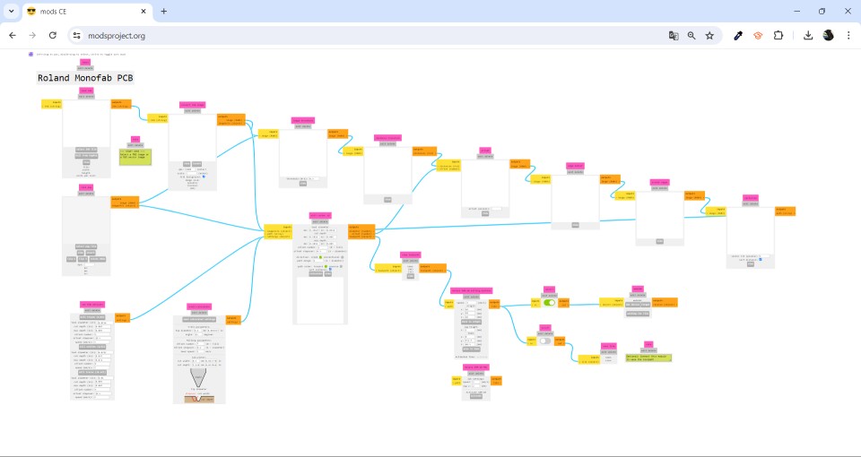
Group assignment week 4
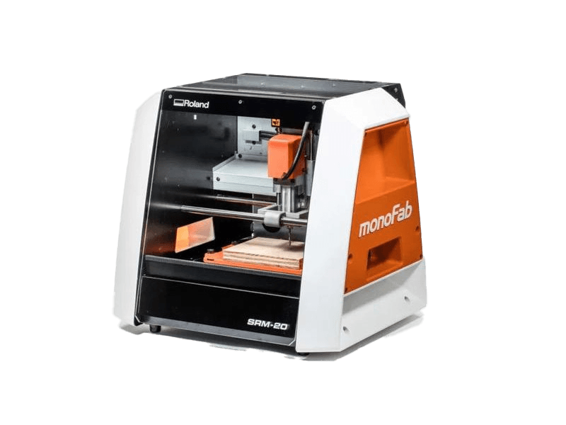
ROLAND SRM-20
The PCB we were given for this week was designed by our consultant Oliver Ochoa and the milling machine I’m going to occupy is going to be a ROLAND SRM-20. Here are some specifications of the milling machine.
- Cutable Material: Modeling Wax, Chemical Wood, Foam, Acrylic, Polyacetal, Acrylonitrile Butadiene Styrene (ABS), Printed Circuit Boards
- Operational Travels in X, Y, and Z: 203.2 mm (X) × 152.4 mm (Y) × 60.5 mm (Z)
- Loadable Workpiece Weight: 2 kg
- Operation Speed: From 6 mm/min to 1,800 mm/min
- Software Resolution: 0.01 mm/step (RML-1), 0.001 mm/step (NC Code)
- Mechanical Resolution: 0.000998594 mm/step
- Spindle Rotation Speed: Adjustable from 3,000 RPM to 7,000 RPM
- Interface: USB
- Operational Noise: During operation: 65 dB(A)
- External Dimensions: 451 mm (width) × 426.6 mm (depth) × 426.2 mm (height) (17.76 in [width] × 16.80 in [depth] × 16.78 in [height])
- Weight: 19.6 kg
Here you can find more information.
How to start?
The first thing to do is to download the strokes that have to be done, these same are on the group page, but I will show them below.
 (1).jpg)
.jpg)
.jpg)
.png)
After that, using the modsproject, I looked for the milling machine that I was going to use to make the traces. This are the steps to find the milling machine that I'm going to use.
1.- open modsproject
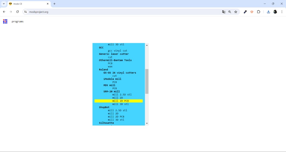
2.- right click and select programs and open program
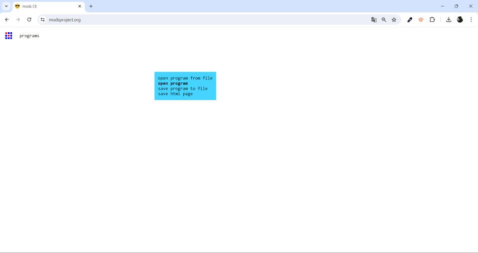
3.- Look for Roland SRM-20 mill 2D PCB
4.- now you can configurate the parameters
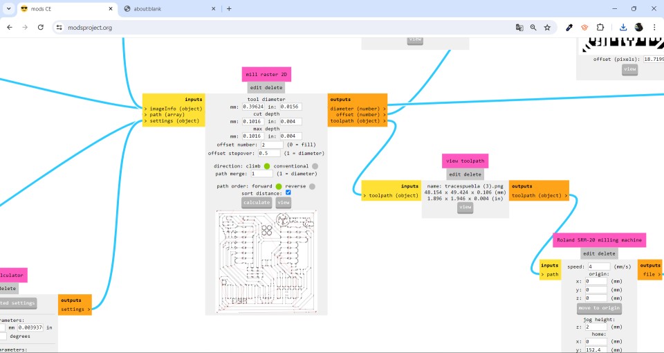
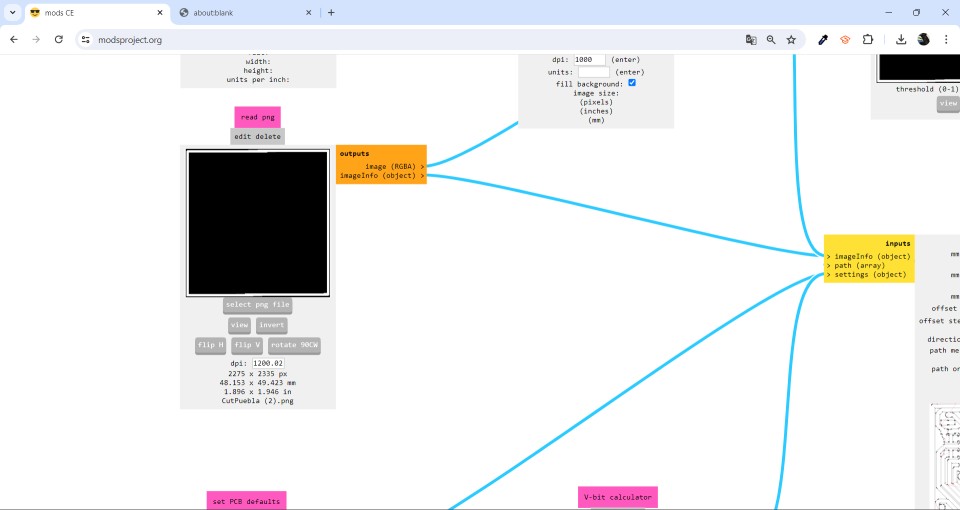
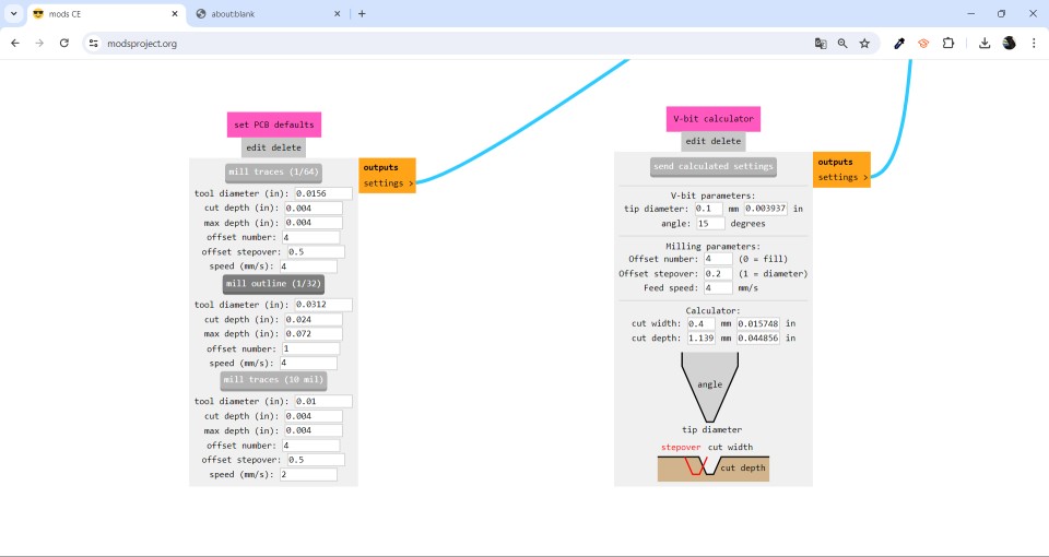
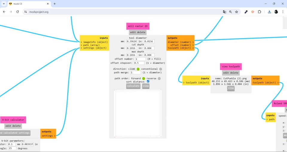
Once inside Mods, we can start to put the necessary parameters for the traces, these parameters are the following:
Traces
1.- Select the file
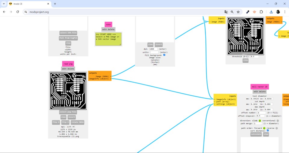
2.- Set PCB defaults (1/64)
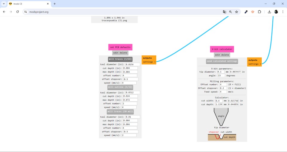
3.- Mill raster 2d
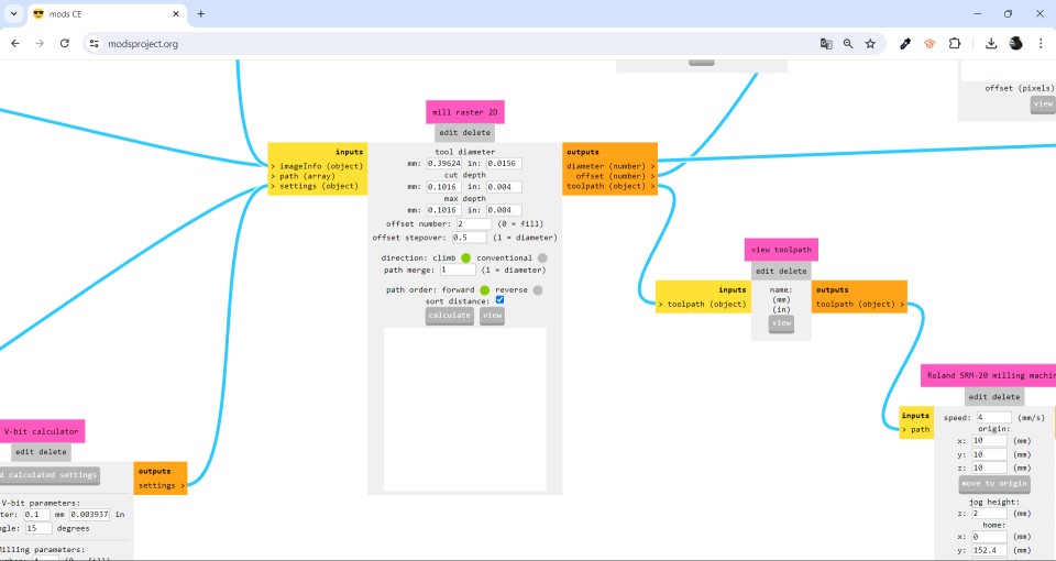
4.- Set up Origin
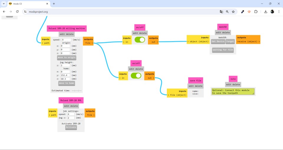
5.- Calculate and download the file
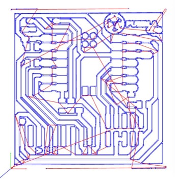
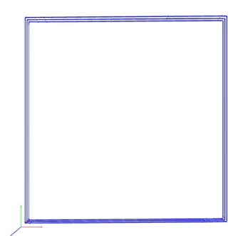
This is how the traces should be
.png.rml)
This file what it does is that it will make the traces that were ordered, in this case are the traces of the circuit, this if you get to cut it.
Once we automatically calculate a file is downloaded in . rml, this file is specific to the Roland SMR 20. Once we have this file of the traces we can begin to modify the cut file.
Cut
The process to modify the cut is practically the same, only that some parameters change, these are the ones that change, the rest remain exactly the same.
Select the file
Set PCB defaults (1/32)
Mill raster 2d
This is how the cut should be
.png (2).rml)
This file, unlike the previous one what does is that, changing the tool this will pierce the plate by the part where the cut was requested, in this case it was only by the edge of the plate.
Controling the milling machine
The SRM-20 was designed with a number of technological advancements that include a touch-button VPanel controller to regulate feed rate, spindle speed and milling on a complete X, Y, Z axes, and a new independent collet system that allows for faster setting of the Z-axis base point and quick tool changes.
.jpg)
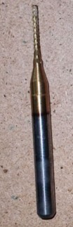
Having the copper plate already placed inside the milling machine is time to place the tool for strokes. This is the tool:
.jpg)
Having changed the tool it is time to put the origins in the milling machine, to place the origins, in VPanel, in the upper right we can place the origins by placing X/Y and Z and automatically that will be their new origin. Preferably, the origin of Z has to be 2 mm before touching the board.
.jpg)
Note: It is important to always make the traces first and after the cut, this to avoid that during the traces are not affected.
Having already established the origins, we can already place the traces that we are going to do, this is done by clicking on Cut/Add/Output and automatically will begin to make the traces requested.
This is how the milling machine works making the traces
Once the machine has finished making the traces, it is time to change the stroke tool to a cutting tool. This is the cutting tool:
Once the tool has been changed, the origins of X/Y remain exactly the same, the only one that is modified is that of Z, this is because the tool is bigger than the previous one.
Now it is time to put the cut file, this is put in Cut/Delate All/Add/Output, the Delate All is used to delete the previous file, because if you do not do this, the cut may fail.
This is how the milling machine works making the cut
This is the final result after tracing and cutting
.jpg)
Soldering
Components
| Qty | Description |
|---|---|
| 1 | XIAO-RP2040 |
| 7 | Resistor |
| 1 | Bottom |
| 3 | Led |
| 15 | Pin |
The soldering procedure is quite simple, the first thing to do is to wait for the soldering iron to be hot enough to melt the tin at the time of contact. Once this sufficiently hot you have to place the piece where we want to solder it, we heat the piece a little touching it with the soldering iron and bring the tin to the soldering iron, this will start to melt and you have to let it melt enough, having already all melted you have to remove the tin and after the soldering iron letting the melted tin solidify to stick the part correctly.
.jpg)
Board soldered
.jpg)
Now it's time to put the board to the test. The first thing I did was download the Arduino IDE program, later I made a program that consists of two LEDs that were soldered blinking and the third LED only blinks when you press the button.
Programming the board
This is the code
Board working with the program
In general, this assignment was very important because it was my first time soldering a board and making it work correctly, at first I had a lot of problems soldering, so I started practicing soldering and desoldering other components so as not to make too many mistakes in the principal board. Although the board was not 100% aesthetic, it worked and with this experience I will improve for the following assignments.