Computer-Controlled Cutting
For this week's assignment, I plan to enhance it by incorporating computer-controlled cutting techniques. Specifically, I will focus on designing a parametric construction kit, which offers versatility as it can be assembled in various configurations. Additionally, I intend to utilize the vinyl cutter to create precise cuts for another component of the project.
Group assignment week 3
What is a parametric design?
Parametric design is an approach to design where the relationships between elements are defined by parameters. These parameters can be adjusted or varied, allowing for the creation of a wide range of possible designs within a defined system. In parametric design, elements are typically defined by mathematical equations or algorithms, which govern their behavior and appearance.
Modeling 2D desing
First part
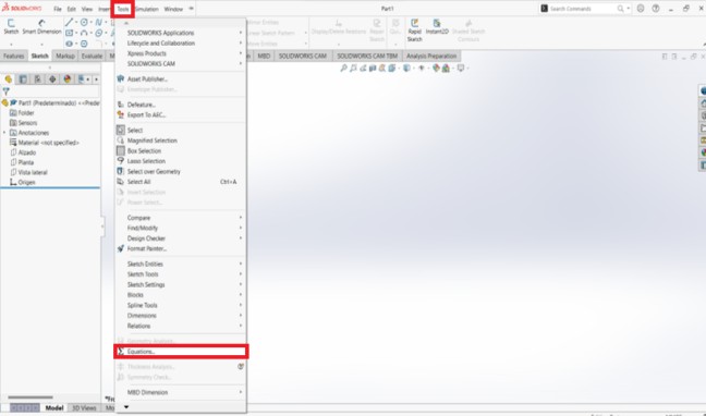
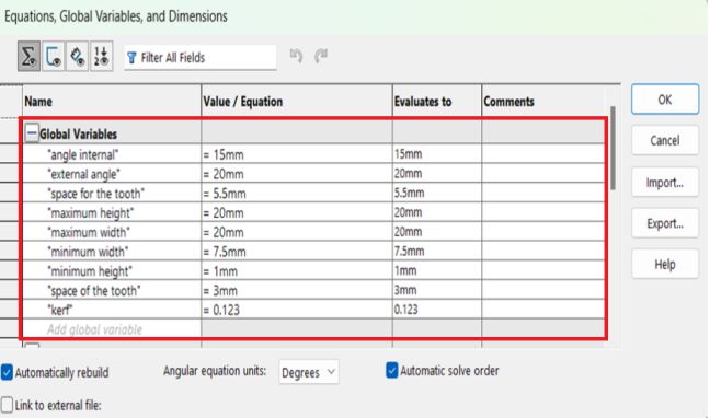
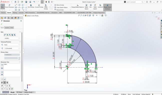
First at all I need to go to the tools section and select equations to start making the parametric drawing.
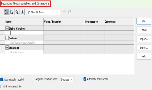
A window will open where we will be able to name the equations and give them a value.
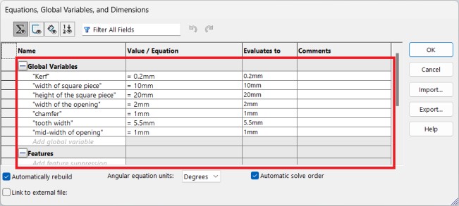
Putting all the equations that are needed to be able to make the drawing.
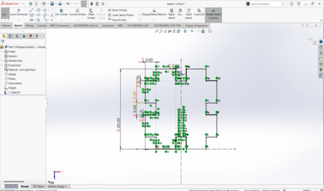
We draw half of the figure to later use the “Mirror Entities” function, using the Smart Dimension tool we select the widths of the figure and in the section to enter a measurement we are going to use the “=” key and call the function we need for that measure.
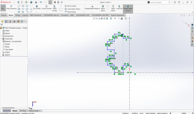
This is how the figure should look.
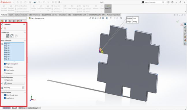
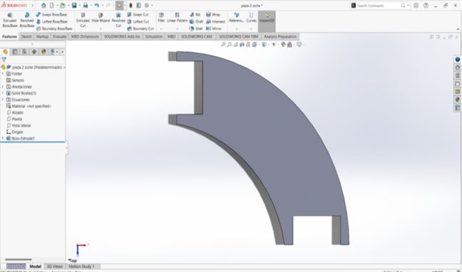
With the part already extruded we are going to use the chamfer tool on a part of some teeth, the measurements we are going to use are 1mm using the function called chamfer.
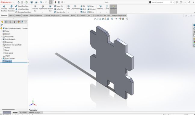
This is how the final figure should look.
Second part
For the second piece it is necessary to have the following equations.
We make this figure and later we add the equations to make it parametric.
Finally we extrude the drawing and it should look like this.
Laser cut
.jpg)
CFL-CMA1080K
This is the laser cutting machine I decided to use for this assignment. These are some of the features it has:
- Work area: 1.00 x 0.80 meters
- Work table: Honeycomb or rod
- Accesory: Double Tube
- Cutting Speed: 0–36,000 (min/mm)
- Engraving speed: 0-64000 (min/mm)
- Power: 100 Watts
- Cutting thickness: 0-25 mm
- Resolution: Up to 4000 DPI (typically between 600 DPI and 2000 DPI)
- Motion accuracy: 0.01 mm
Instructions to use the laser cut
First at all, I need to have the key to use the program. After that, I import the files of the parts that I wanted to cut. Once I had the parts in the program, I needed to put some instructions to be able to make cut. These were the instructions:
.jpg)
After that, I put the origin where I wanted to start the cut, but before start the cut I scaled it to be sure that the cut would be right. Once everything were good, I started the cut.
Video using the laser
These are the results after laser cutting and some assembles that I made with these pieces.
.jpg)
.jpg)
.jpg)
.jpg)
.jpg)
.jpg)
Vinyl cut
For the cut in vinyl, I will use a Silhouette Portrait 3, this vinyl cutter has Alberto Blanco, one of our advisors for the Fab Academy. Here are some of the cutter features.
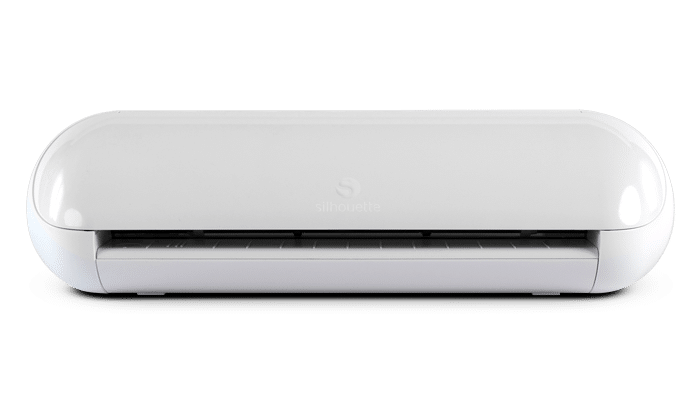
Silhouette Portrait 3
The Silhouette Portrait 3 cutting plotter is a compact machine that allows you to create projects with incredible precision. From cutting labels to creating custom stickers.
- Cutting area: 8" x 12"
- Maximum thickness of the material: 2 mm
- Interface: USB 2.0 / Bluetooth
- Weight: 3 lb
- Software:Silhouette Studio® versión 4.3.341 o superior
If you want to know more about Silhouette Portrait 3 Click in here. and to download the software to use the vinilio cutter Click in here.
Now, fo the vinyl cut I decided to use the Nike logo. The first thing that I did was import the image to the program to make the cut. After the import I choose the size of the image and the position of it. Before make the cut, I put some instructions to make the perfect cut. These were the instructions:
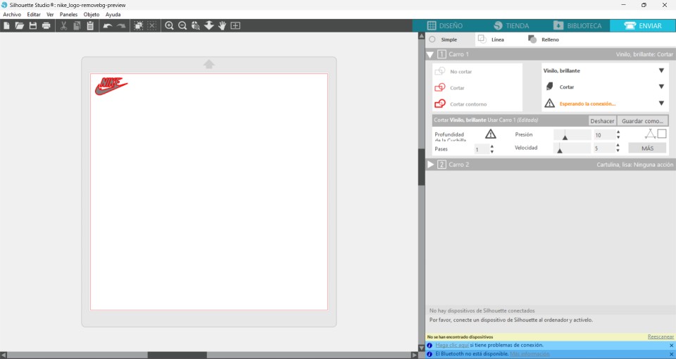
This are the machine cutting
This is the result of the cut.
.jpg)
.jpg)