Computer-Aided Design
For this week's assignment the task was to model some experimental part of my final project with the help of 3D and 2D CAD software.
What is a CAD software?
CAD, an acronym for Computer-Aided Design, pertains to a software application that enables the creation, alteration, analysis, and enhancement of designs and models in both two and three dimensions. It facilitates the convenient manipulation of basic geometric elements within the software.
3D Modeling
For 3D modeling I tried working with programs such as CATIA, SolidWorks and Fusion 360. I chose these three software because they are the most common in engineering and also because they are the ones our instructors recommended for this assignment.
Note:The unit of measurement which I am using is millimeter (mm).
SolidWorks
SolidWorks is a program that I have already used on many occasions so I did not have any complications when using it, apart from having taken a course not long ago on how to use it. Apart from this, it is the software most used in my career, being this the main reason why I have decided to work with this software for this assignment.
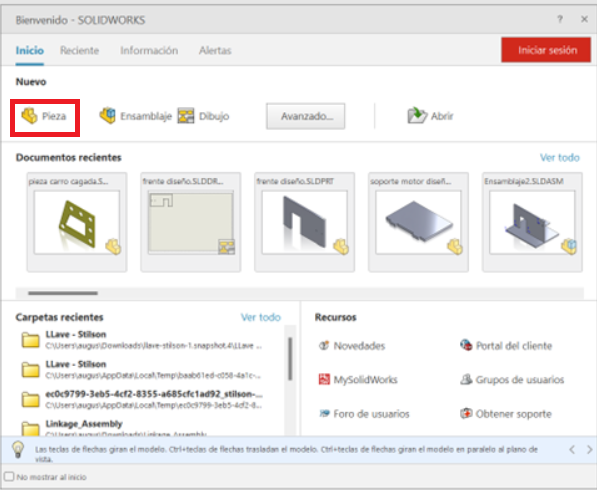
First of all, we open SolidWorks and select the option that says new part.
Now that I have defined the software that I will use it is necessary to start making the part that I want to design.
Note: The unit of measurement I am using is millimeter (mm).
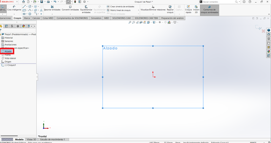
Select a plane in which we are going to start making our design. Once you got it, click on the right and select where it says sketch.
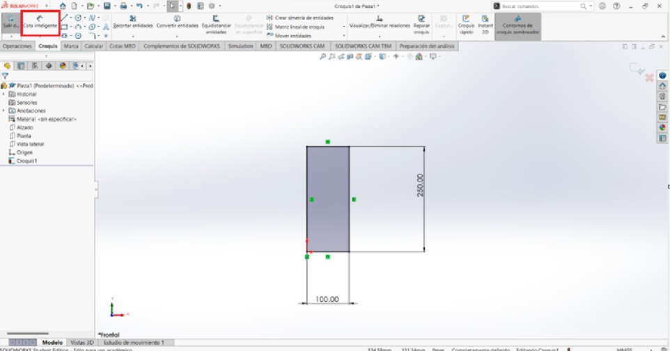
With the line tool we can make the following figure.
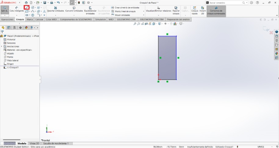
With the smart dimension tool we give measurements to the figure.
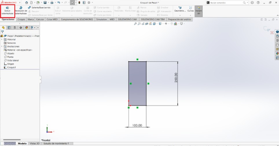
In the operations section we are going to use the extrude tool to give volume to our drawing.
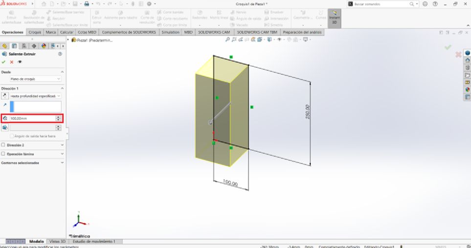
We will give it a volume of 100mm and accept it.
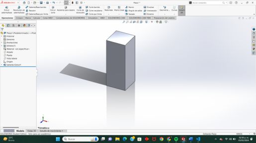
Up to this point the figure should look like this.
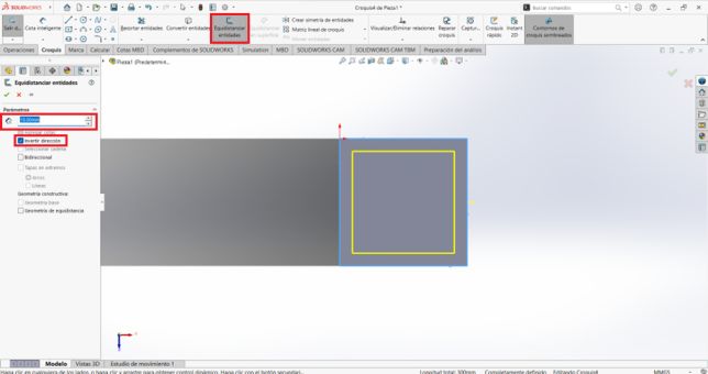
With the equidistance tool, we are going to select the 4 faces of the square. We click to reverse direction and we give it a measurement of 10mm and we click to accept.
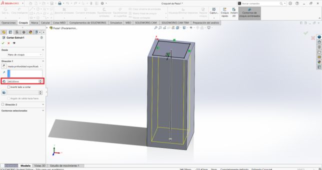
We go to the operations section and select the extrude cut tool. We give a depth of 240mm and accept.
Now we select this face and select sketch so we can edit it.
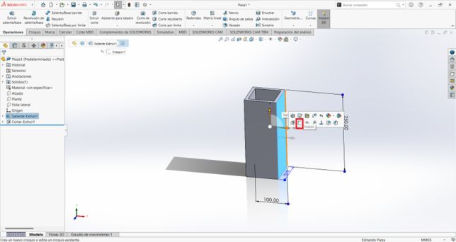
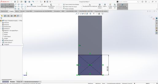
We make a rectangle at the bottom of the figure.

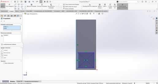
We make the width of the bottom part of the rectangle collinear with its respective parts of the previously made figure. To make them collinear, we press the CNTRL key and select the part that we want to be collinear and select the collinear relationship and click OK and do the same with the other faces.
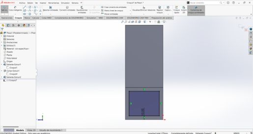
We give the square a height of 85mm and we are going to extrude the drawing with a volume of 200mm.
Using the equidistance tool again, we reverse direction and measure 10mm.
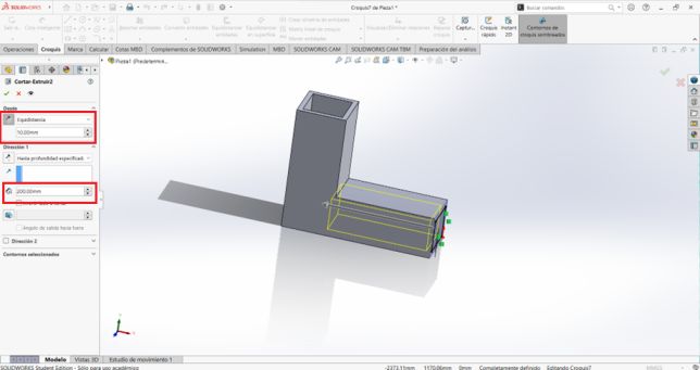
Now we are going to make a slightly different cut since we do not want everything to be cut, we want to keep a distance, for this we are going to make the cut not from the sketch, but rather equidistant at 10mm and have a distance of 200mm and we accept it.
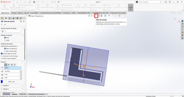
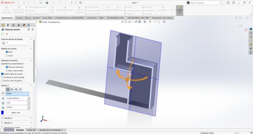
With section view you can see the cut better, since it cannot be seen with the naked eye.
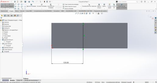
Now we select the lower part of the figure to edit it with a sketch and we are going to draw a line that will be 125mm to the right of the left end of the figure but that will be inside it.
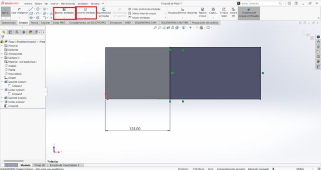
Now using the convert entities tool we are going to select the right side of the figure and its two height sides and click OK. Using cut entities we will trim the excess that remains from the rectangle that was just created. In the end it should be like this.
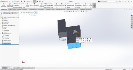
Now we are going to extrude the figure with a volume of 250mm and click OK. We select the bottom part of the figure to edit it.
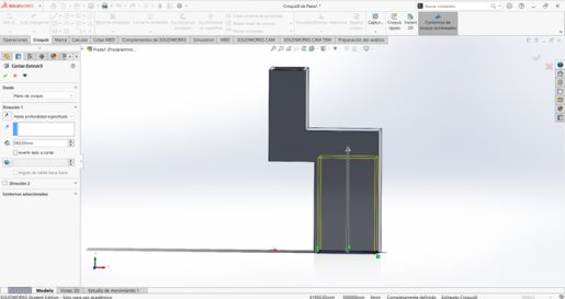
Using the equidistance tool we are going to select the four faces and reverse the direction and give it a distance of 10mm. We extrude a cut through the plane with a volume of 260mm and accept it.
Using the section view tool it looks like this.
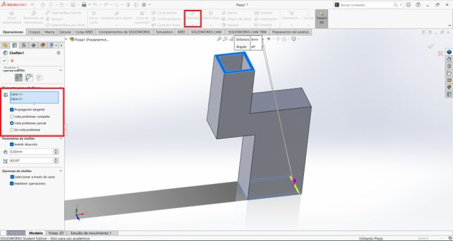
Following the design of the part, we are going to use the Chamfer tool found in the operations window and we are going to select the two faces that are open, we give a distance of 5mm and 45 degrees and we reverse direction and accept.
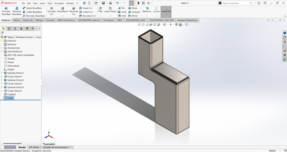
I decided to made a fillet in some faces of the part. To edit the material the figure is made of, we go to the material section and click on edit material, I chose stainless steel. Finally, the figure will look like this.
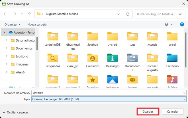
Now all that remains is to save the piece to File and save as.
.jpg)
Render of the final part

Video of the part
3D MODEL
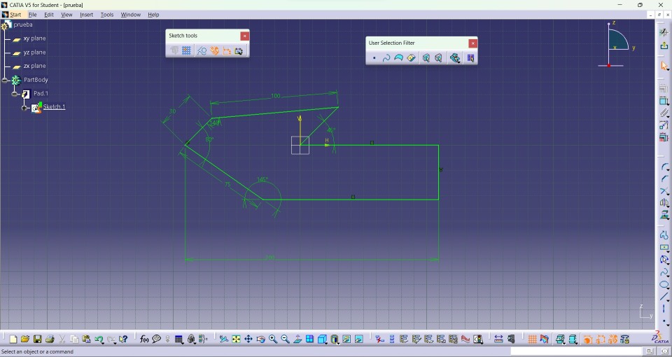
CATIA V5
CATIA V5 was one of the first CAD design software that I began using, but after no using it for too much time, I found it difficult to fit its tools and had too many outdated ones. This led me to decide not to use it.
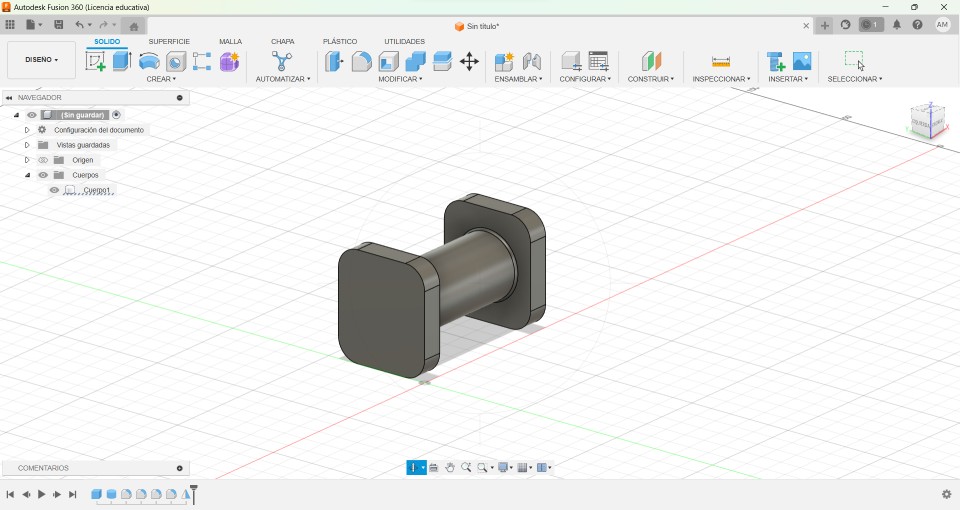
FUSION 360
Fusion 360 is a software that I had never used before, but you need to learn how to use it because it is very employed in the engineering area. It was a little complicated to use it at first but soon after using it was making it easier to use it, but I feel that there are many functions that are a little hidden and for this reason I decided not to use it.
Catia V5 vs FUSION 360
| Developed by Dassault Systèmes, CATIA V5 is CAD software widely used in industries, especially in sectors like automotive, aerospace, and mechanical engineering. It is known for its ability to handle complex and large assemblies. | Fusion 360 is a CAD/CAM/CAE platform developed by Autodesk. It's designed to be more accessible and cloud-centric, with integrated tools for design, simulation, and manufacturing, making it popular among independent designers. |
| While CATIA V5 can integrate with product lifecycle management (PLM) systems to facilitate collaboration and data exchange, it's not as cloud-oriented as Fusion 360. | Fusion 360 is designed for cloud collaboration, making it easy to share designs, collaborate on projects, and access files from anywhere with an internet connection. This makes it ideal for distributed teams and collaborative projects. |
| CATIA V5 is often used within larger product lifecycle management (PLM) systems and integrates seamlessly with other Dassault Systèmes software like ENOVIA and SIMULIA. | Fusion 360 offers integration with other Autodesk software such as AutoCAD, Inventor, and Revit, providing a more interconnected ecosystem for users who work with multiple Autodesk products. |
| CATIA V5 is primarily a desktop-based software available for Windows operating system. There are versions for UNIX and Linux, but they are less common. | Fusion 360 is a cloud-based platform accessible through a web browser and is compatible with Windows and macOS operating systems, providing more flexibility in terms of platform choice. |
CATIA V5's advanced design capabilities, industry recognition, comprehensive simulation tools, interoperability with PLM systems, precision modeling capabilities, and available training resources make it a better choice than Fusion 360.
2D Modeling
For 2D modeling I tried different programs such as AutoCad, Illustrator and FreeCad. I decided to use the LibreCad program because its interface simplifies some of the usual tools of more sophisticated applications.
Note: The unit of measurement I am using is millimeter (mm).
LibreCad
The first thing I did when I downloaded the program was to start using the line and start drawing. The program is vector so it has a point (0,0) and I started to draw what was the front of a dog house.
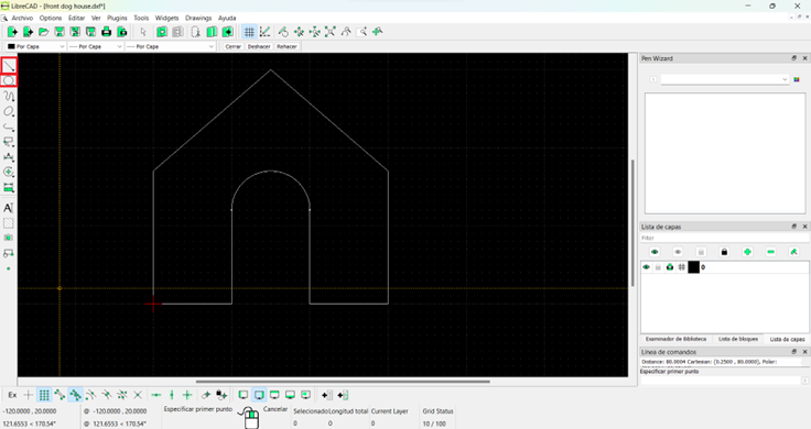
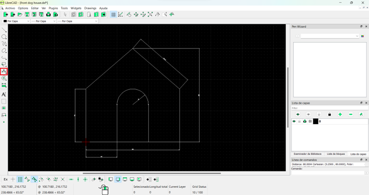
The second thing I did was give measurements to the drawing with the measurements tool that the program has.
And this is how you can save the file in FreeCad