COMPUTER CONTROLLED MACHINING
Also CNC, this manufacturing method uses pre-programmed software to control tool movements and speeds. There are various variants of CNC, such as milling machines, drills, water cutters, among others. This procedure is based on the G or M code, which includes the instructions and parameters for the tools. First, a design is created in CAD, and then the code is generated using a postprocessor.
Group assignment
This week my teachers taught us how to use the CNC router and the software to generate tbones and dogbones.
Review of how I guided myself this week:
Security First
The CNC router is a fairly efficient tool, but it is also quite risky, so it can cause serious accidents and it is necessary to know how to prevent all these risks. To prevent any accident it is necessary to use safety equipment:
- Glasses
- Security boots
- Face mask
- Earplugs
- Lab coat
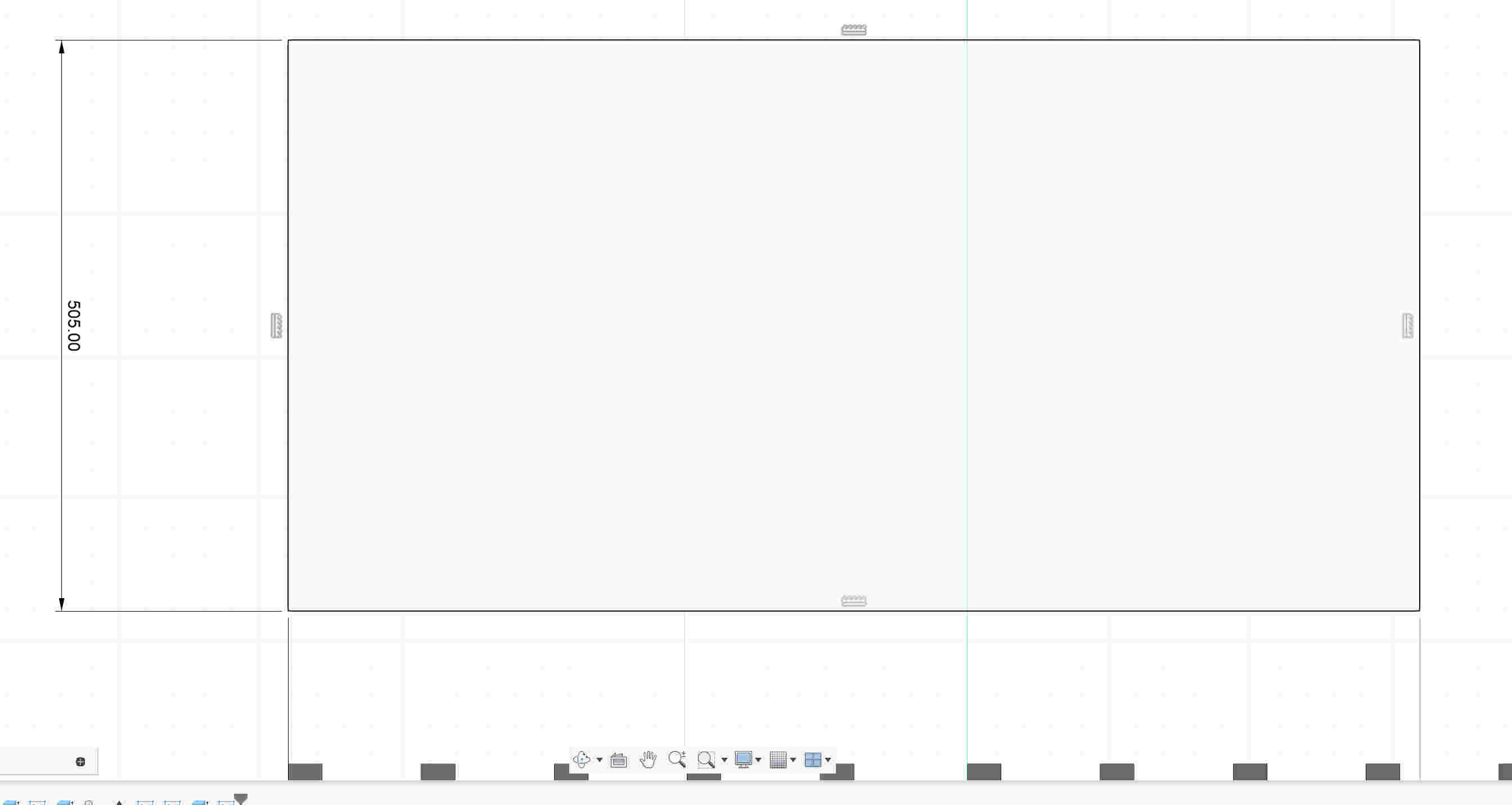
- To start designing i will have to create a new sketch in Fusion 360 and choose the plane where i want to work.


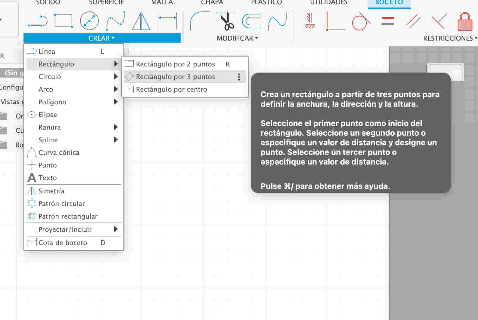
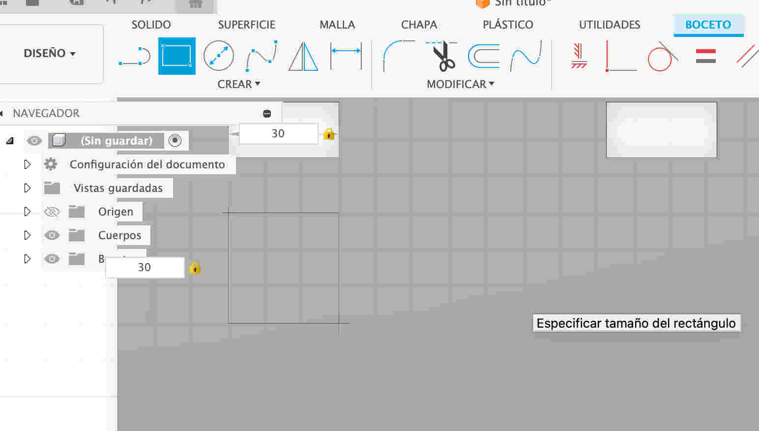
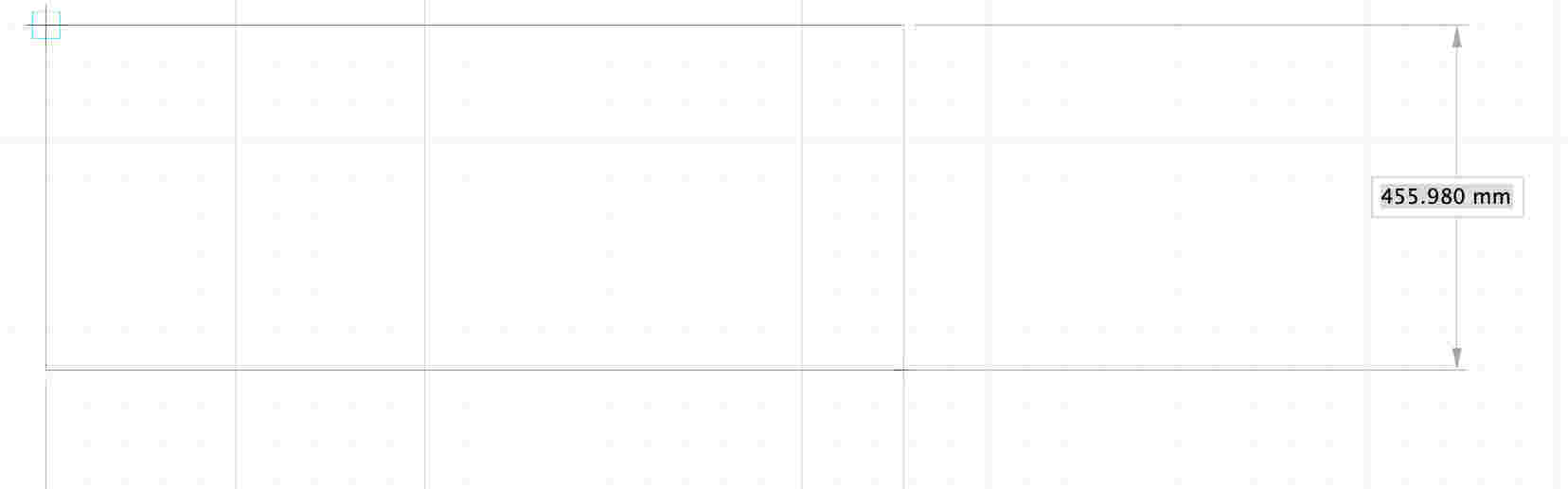
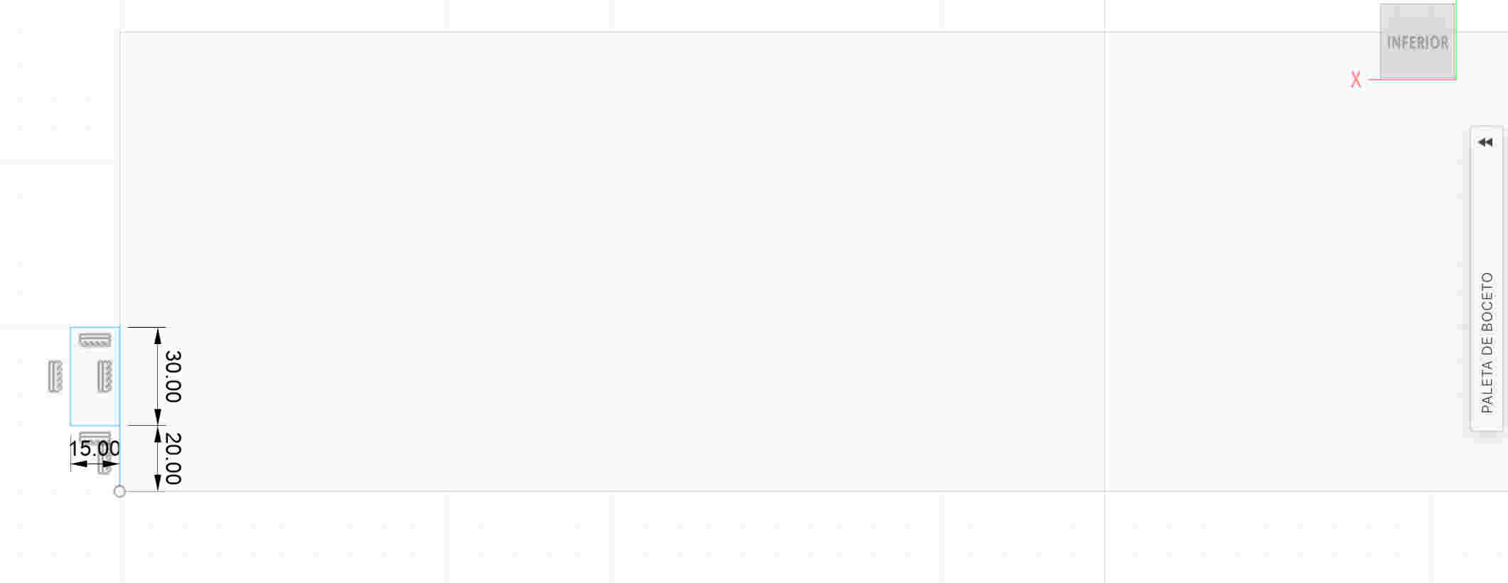
- I will click on the top part of the program which is called sketch, i will click on the option to create a rectangle and i will give it specific measurements
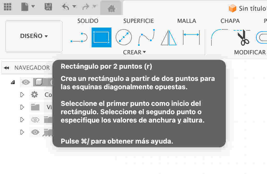


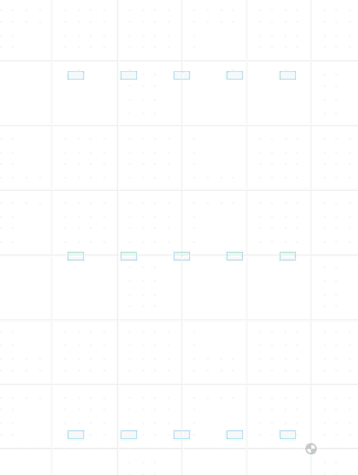
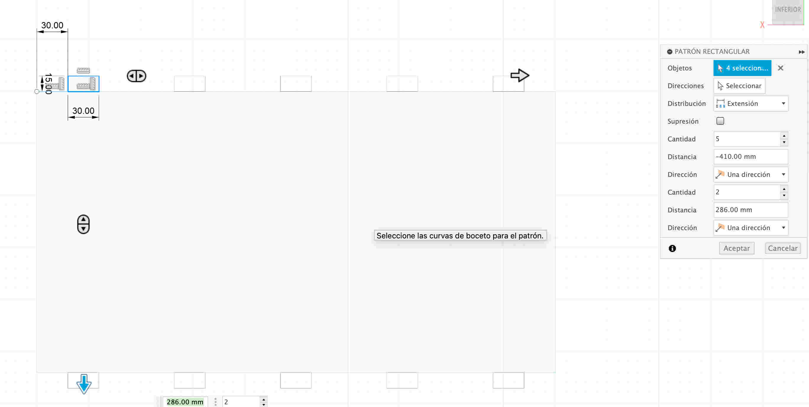
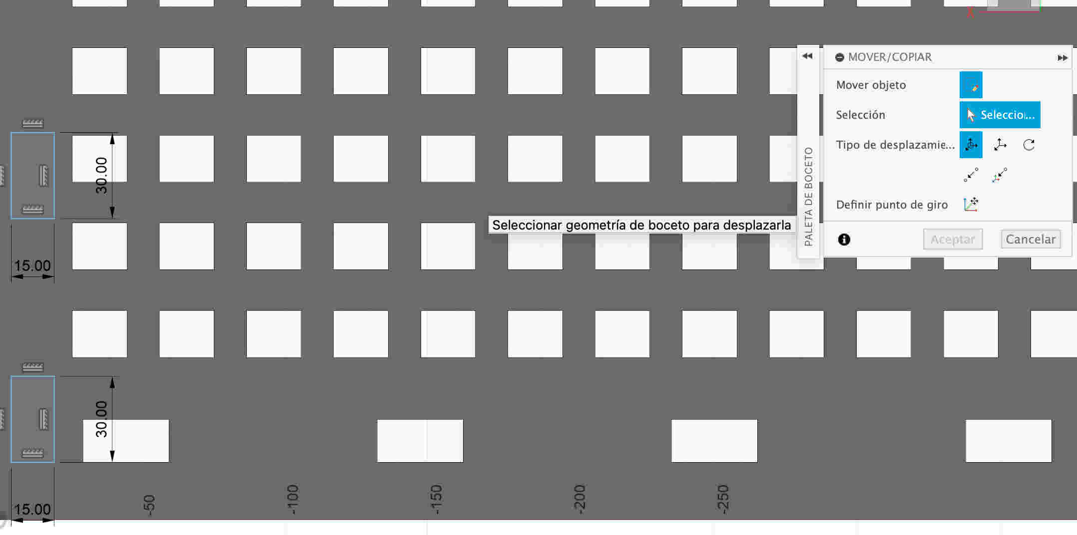
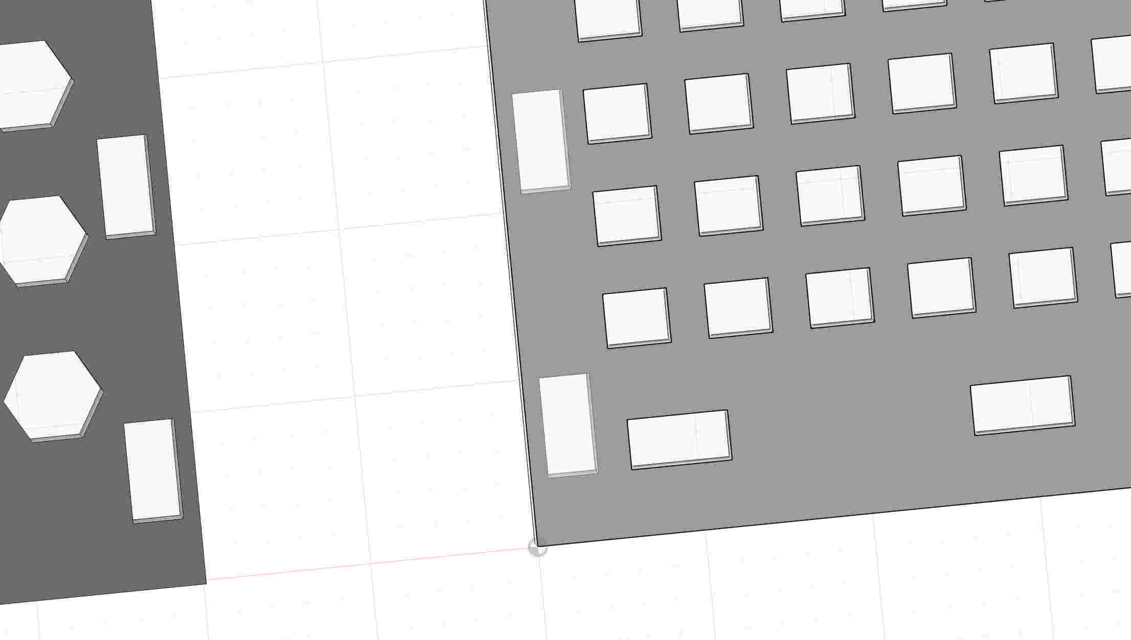
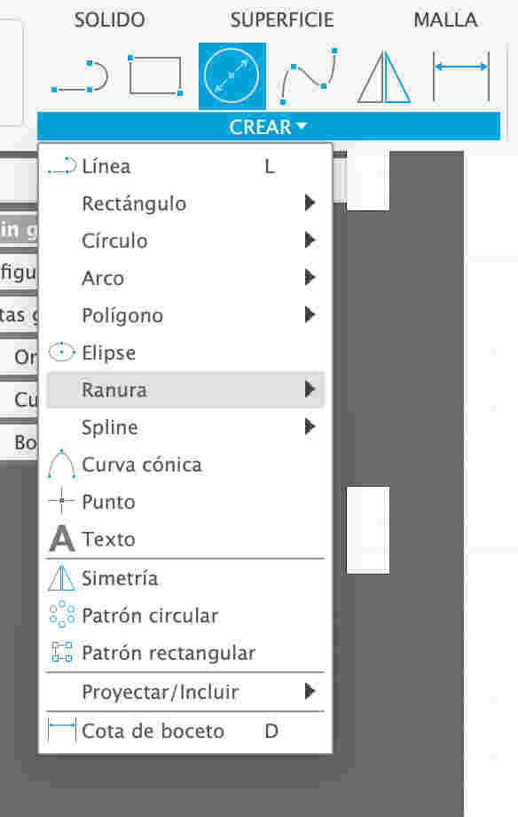
- To create a pattern using a rectangle, I first click on the 'rectangle' option in the toolbar. Then, with the rectangle selected, I drag it to create a series of repetitions until I reach the measurement of the original rectangle. This process allows me to generate a continuous pattern based on the size and shape of the original rectangle.
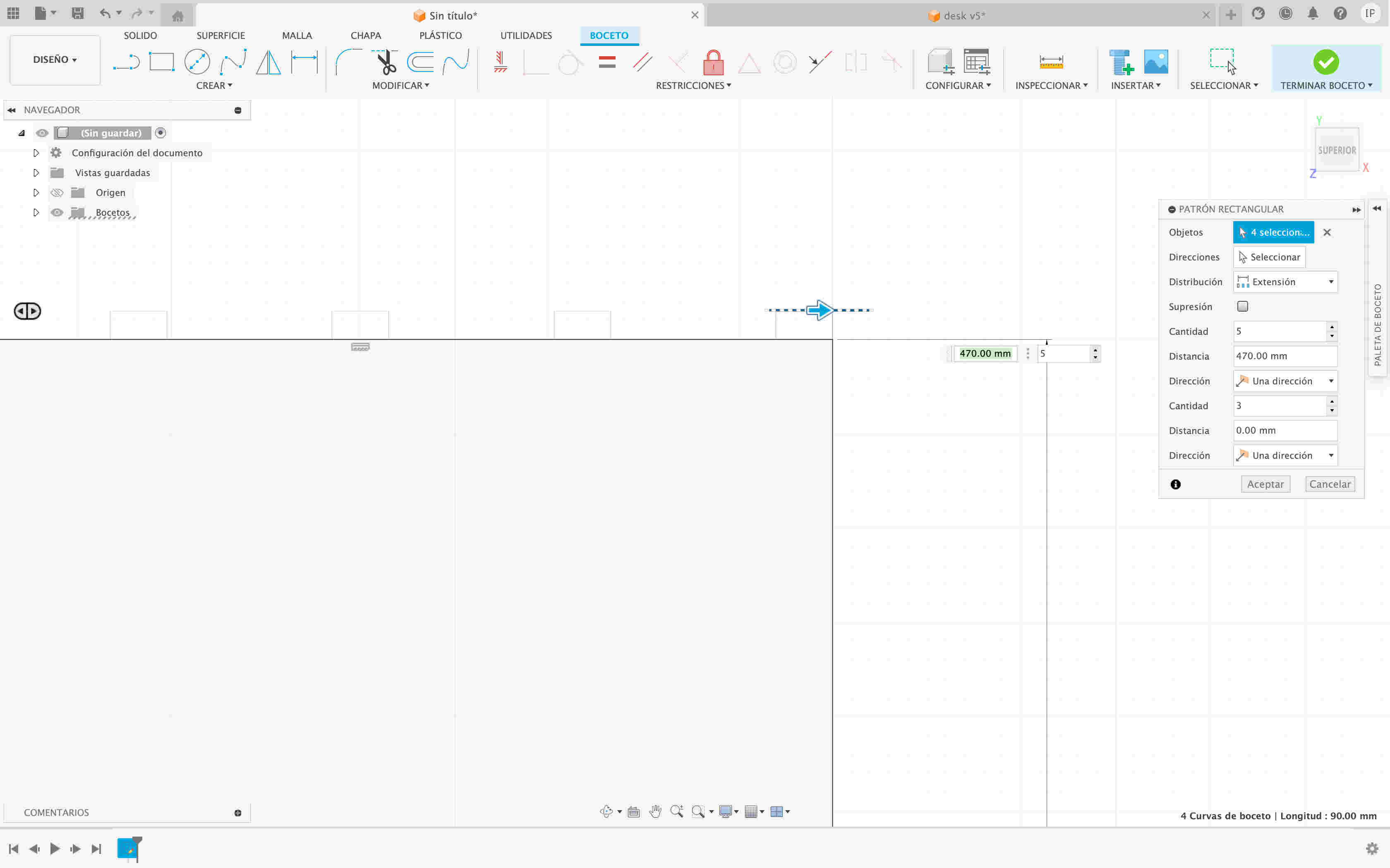
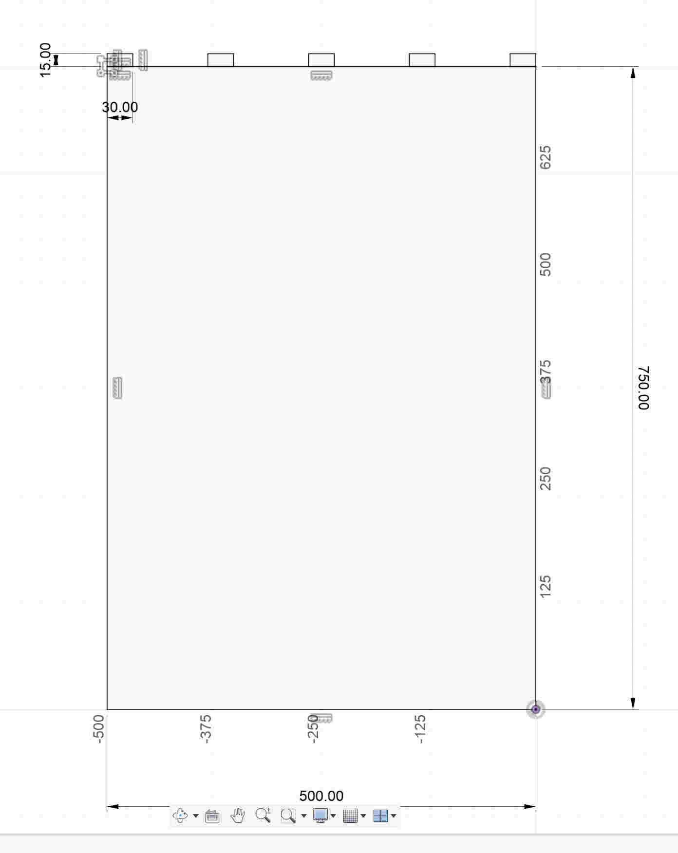
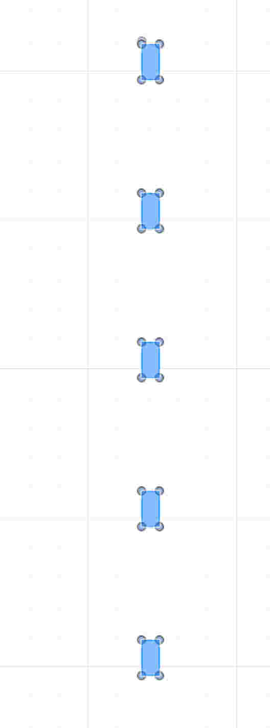
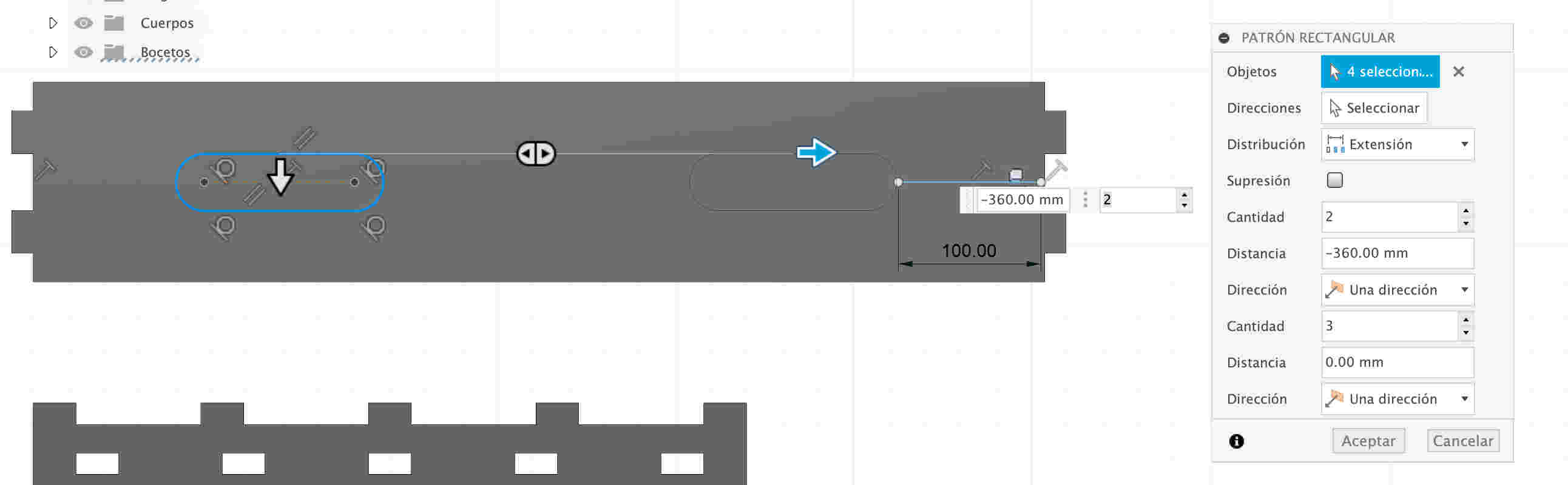
- First, let's place a rectangle in a specific position. Next, we will create an array containing multiple instances of this same rectangle in different positions so that it can be assembled with another shape.
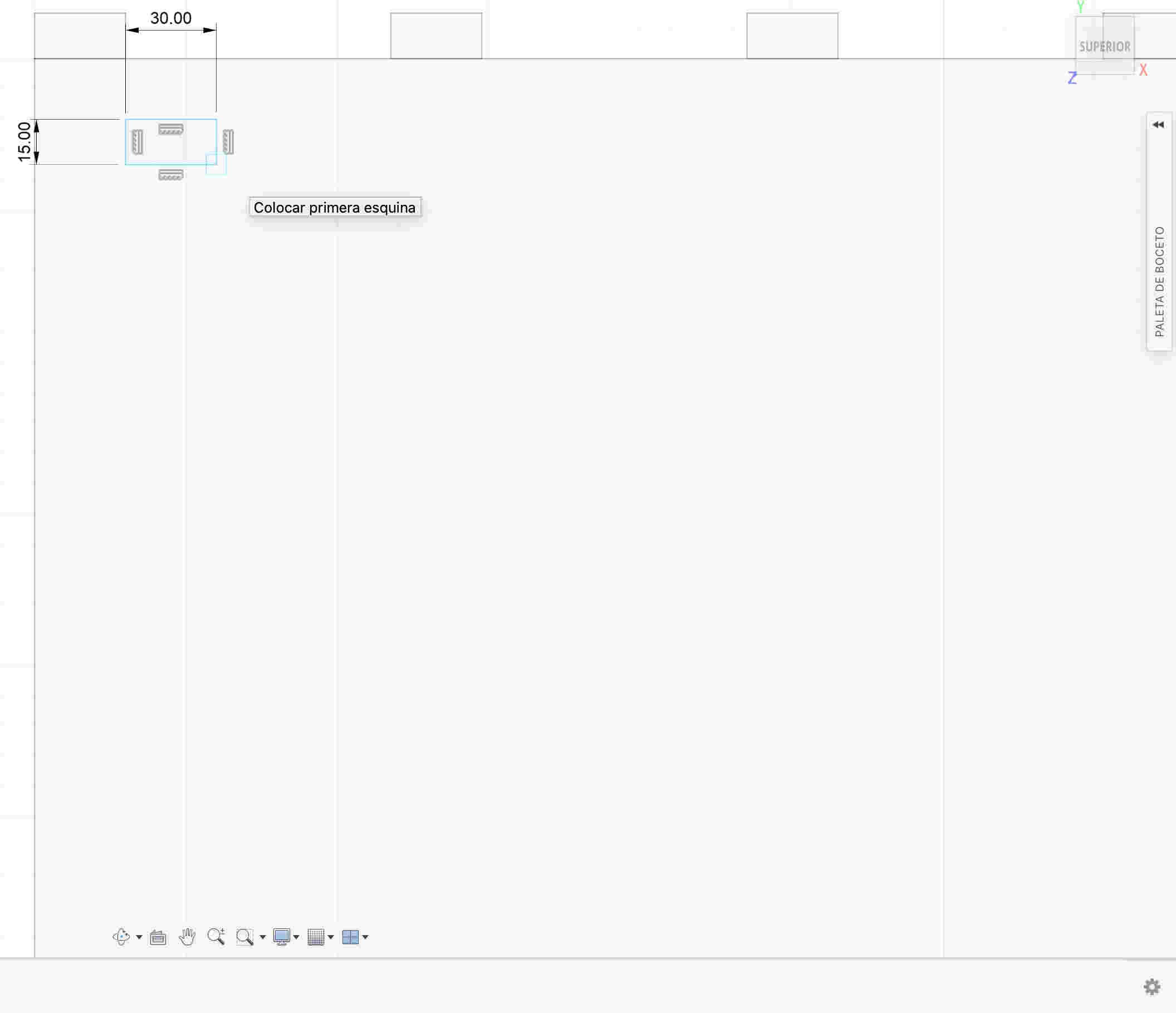


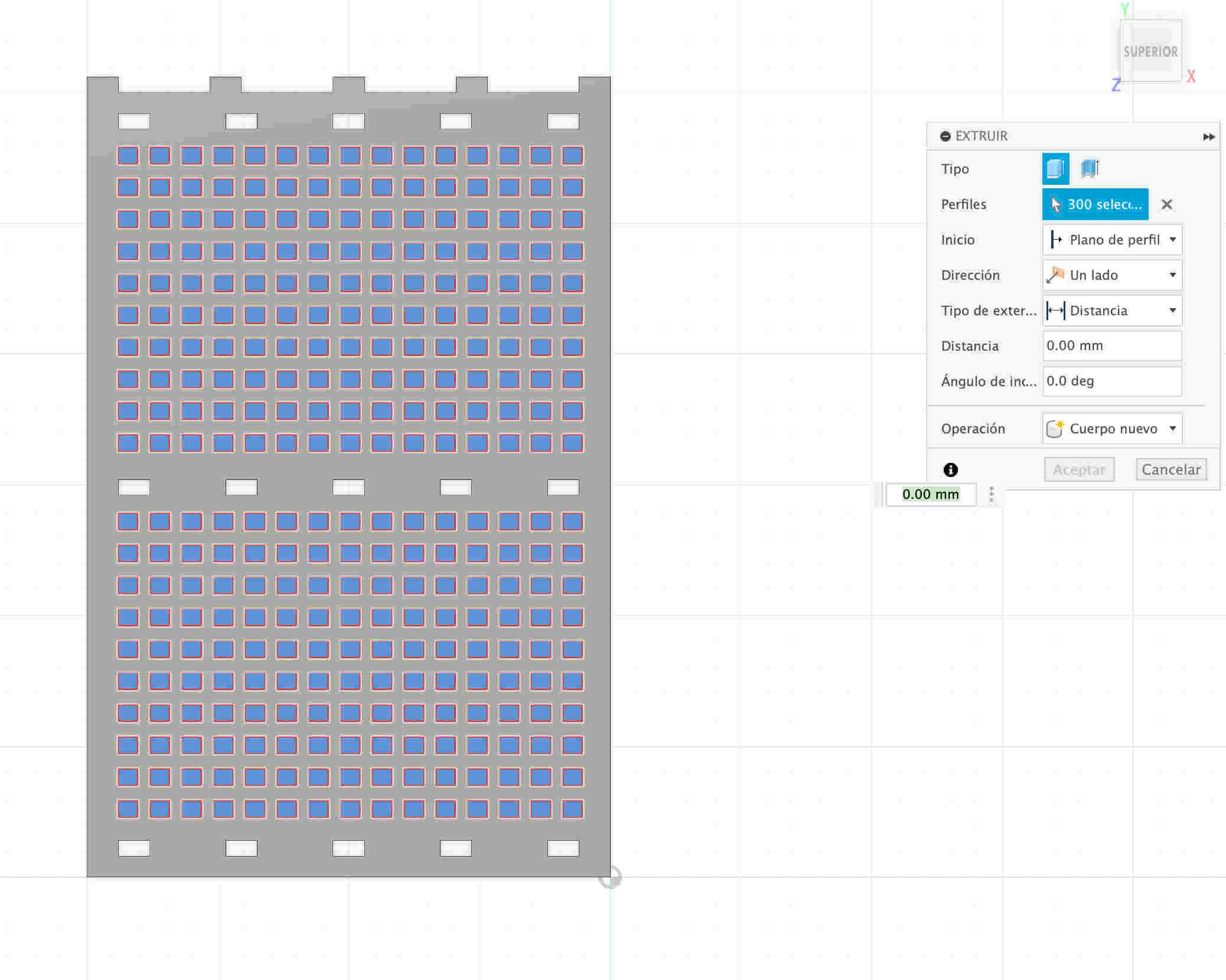
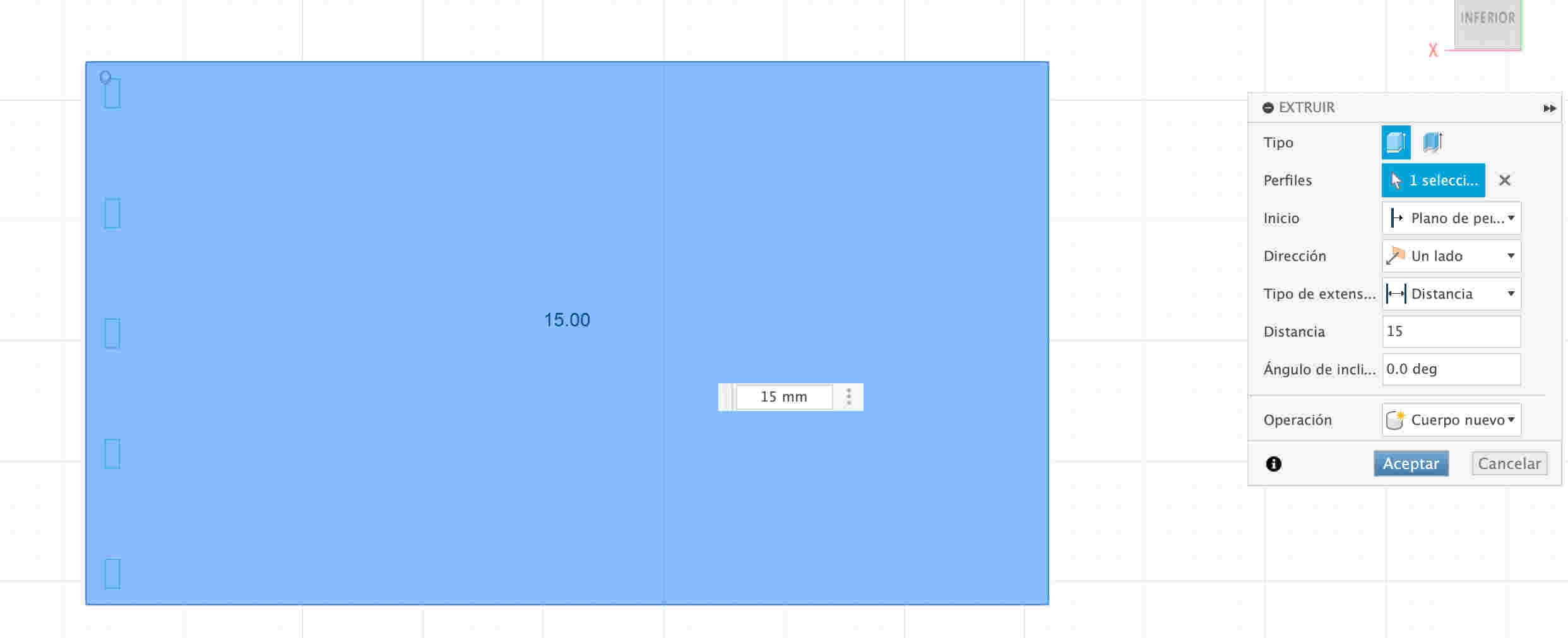
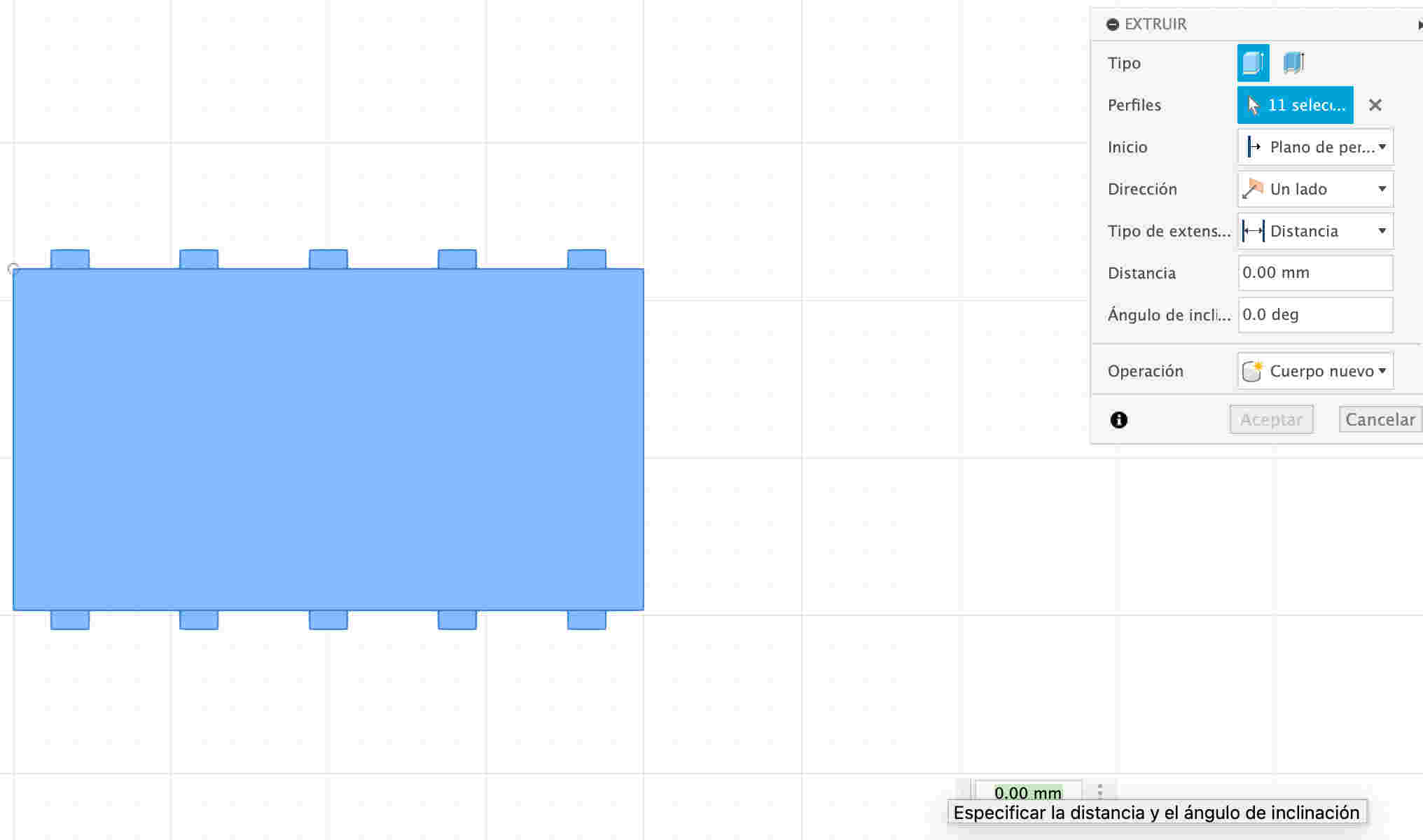
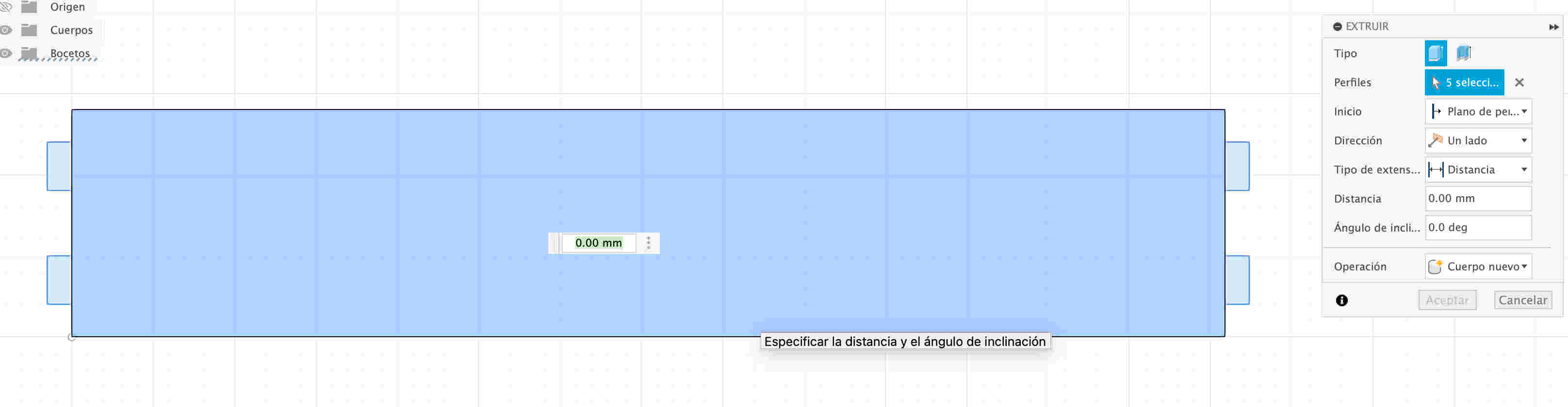
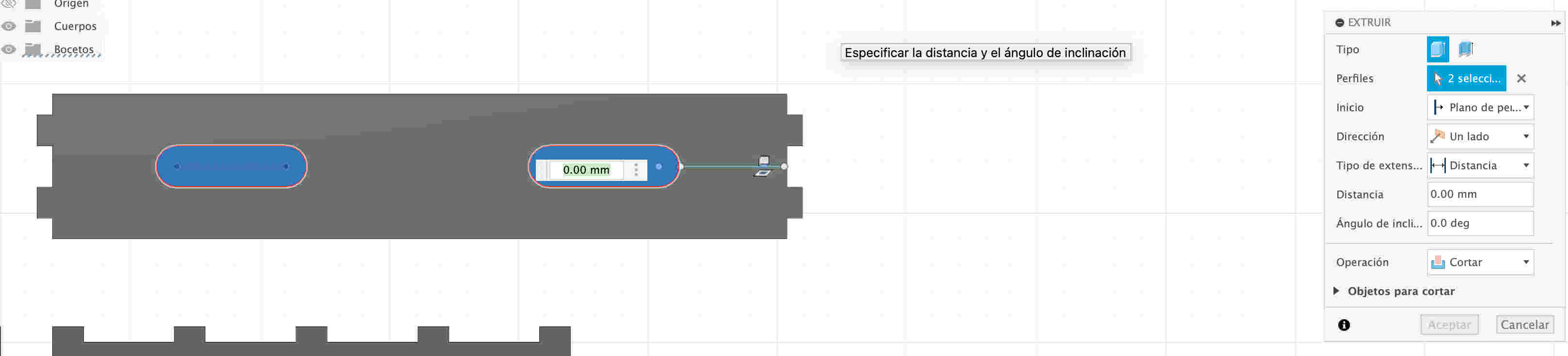
- I extrude the rectangle so that the rectangles that i had generated by matrix are hollow
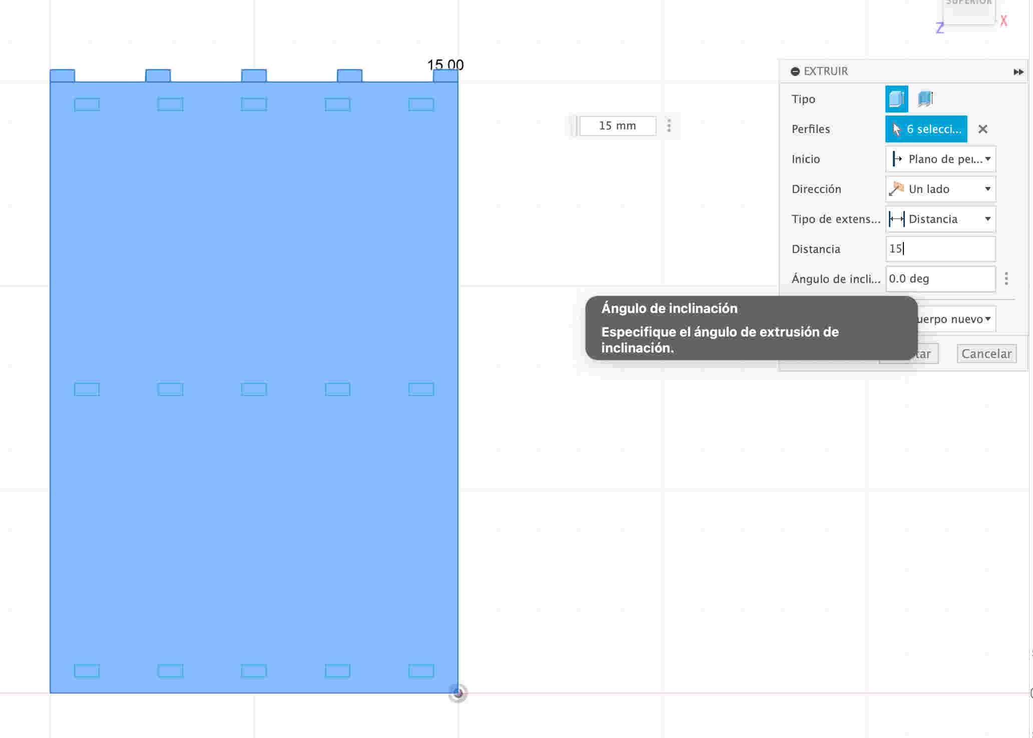

- Select all the internal rectangles and then give it the option to cut, on the right side of the program. In order to make it have an effect of hollow rectangles.
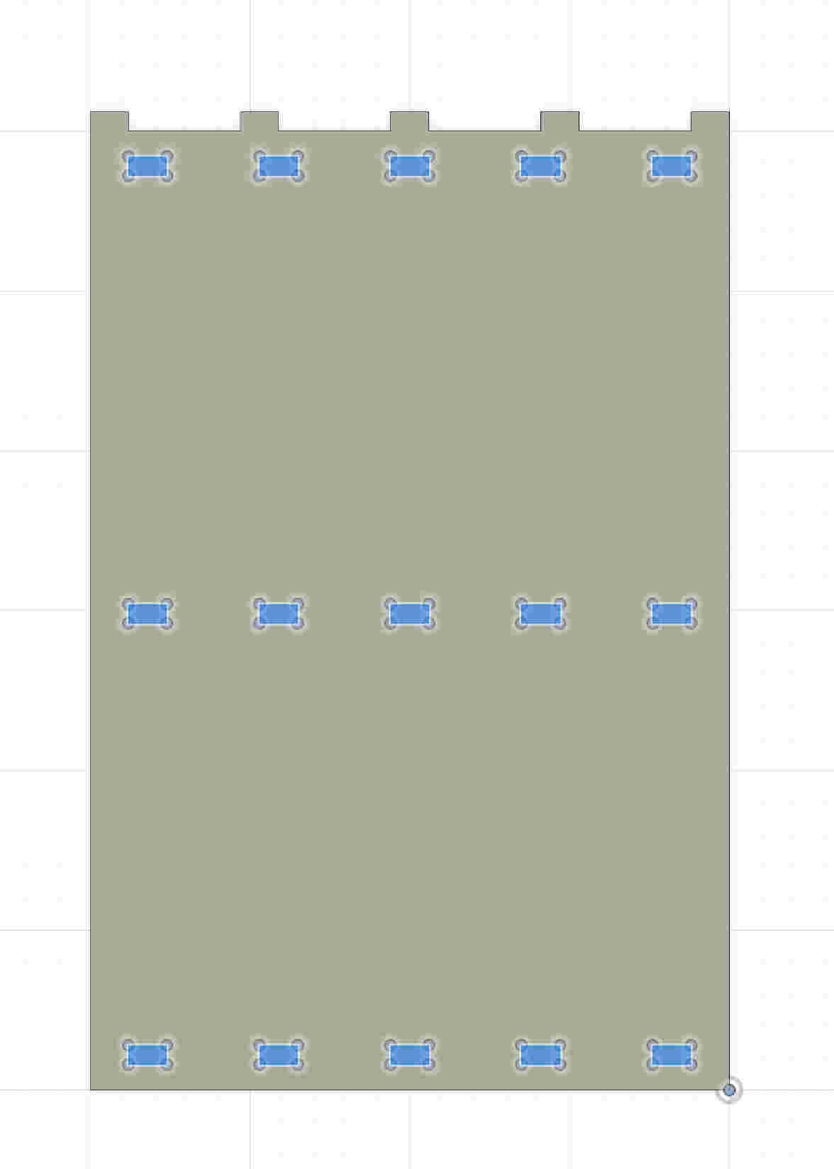

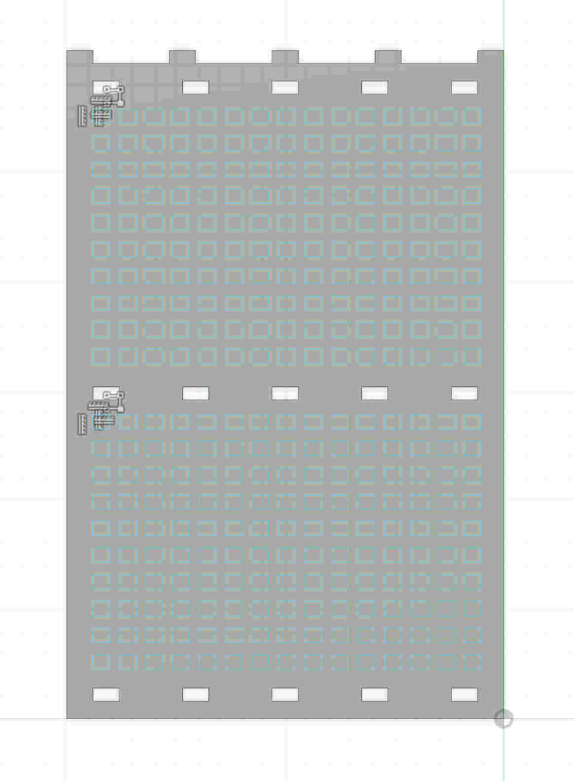
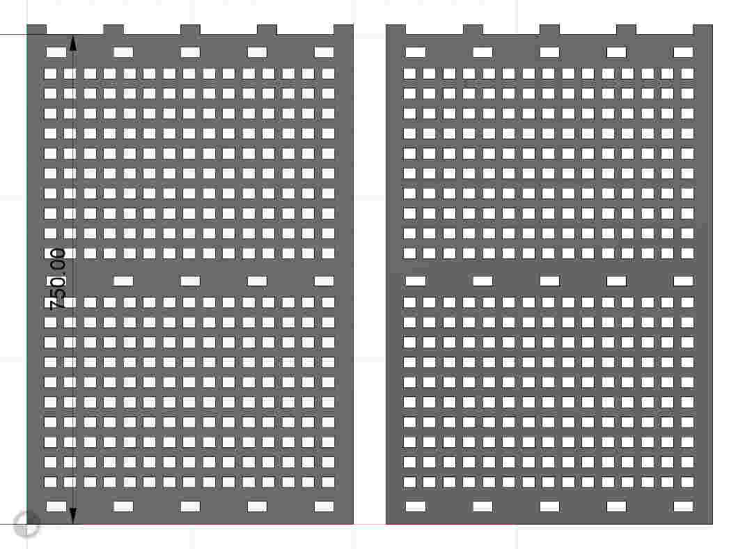
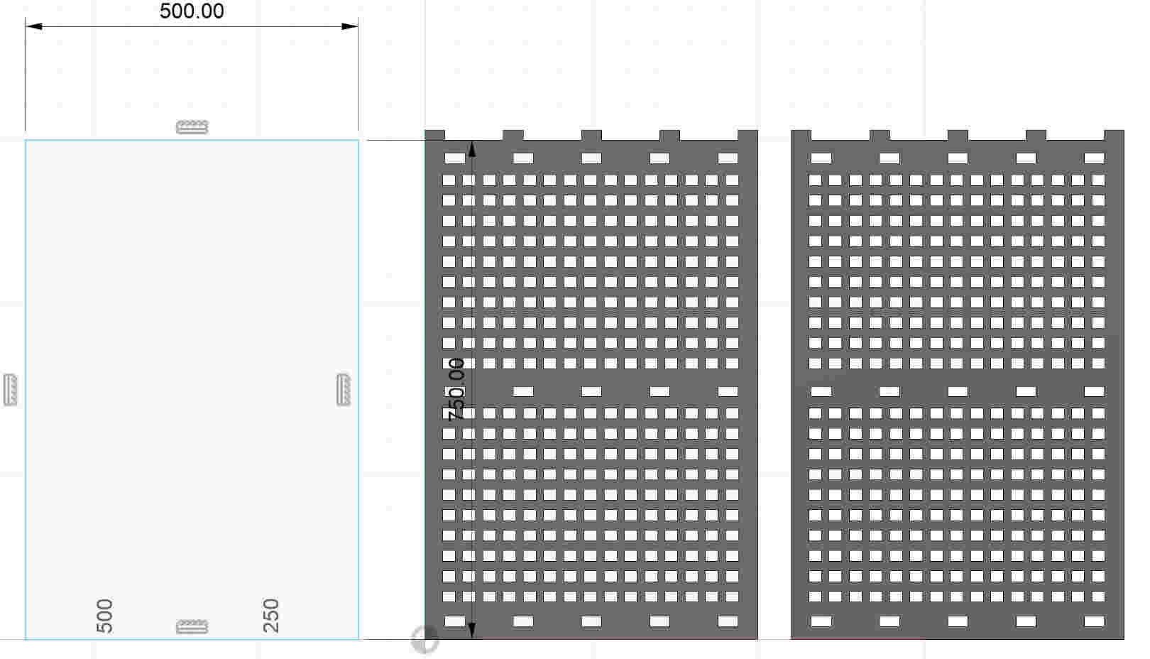
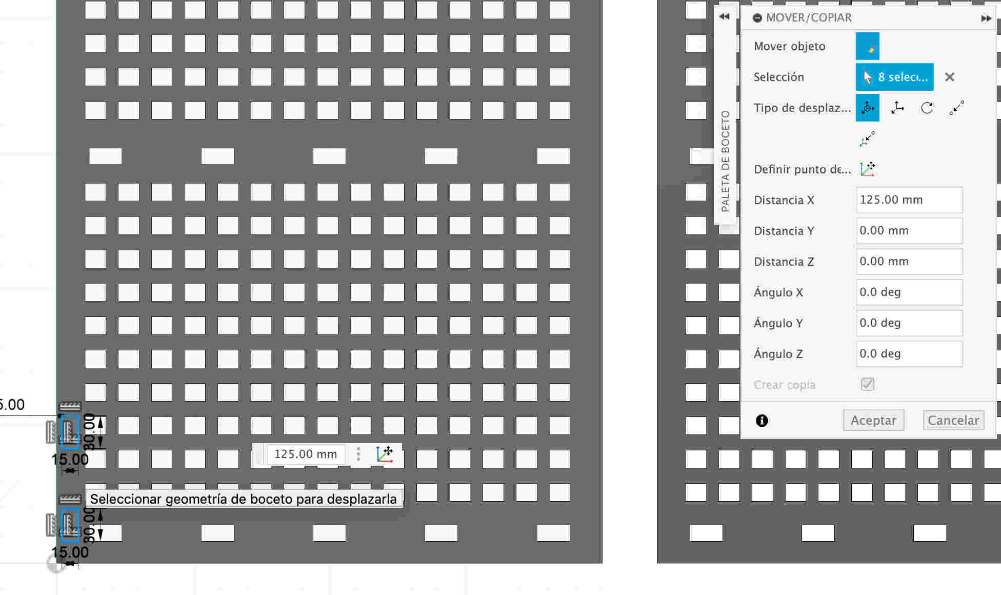
- Now I will create a square with the rectangle option by 3 points and to be able to give it a matrix from top to bottom I will click the rectangular pattern option
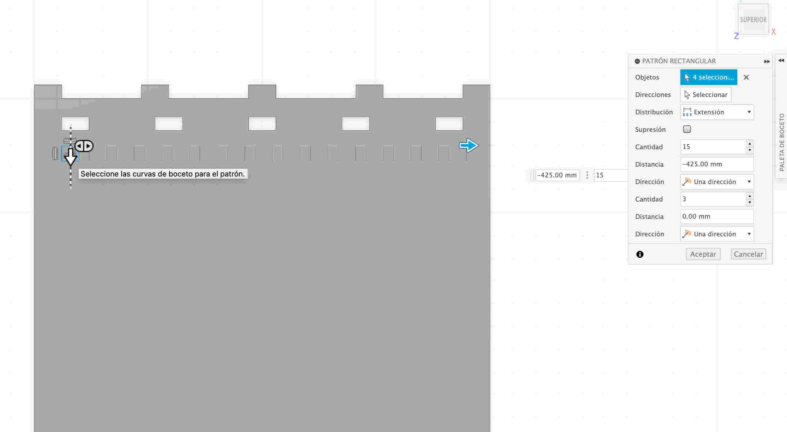
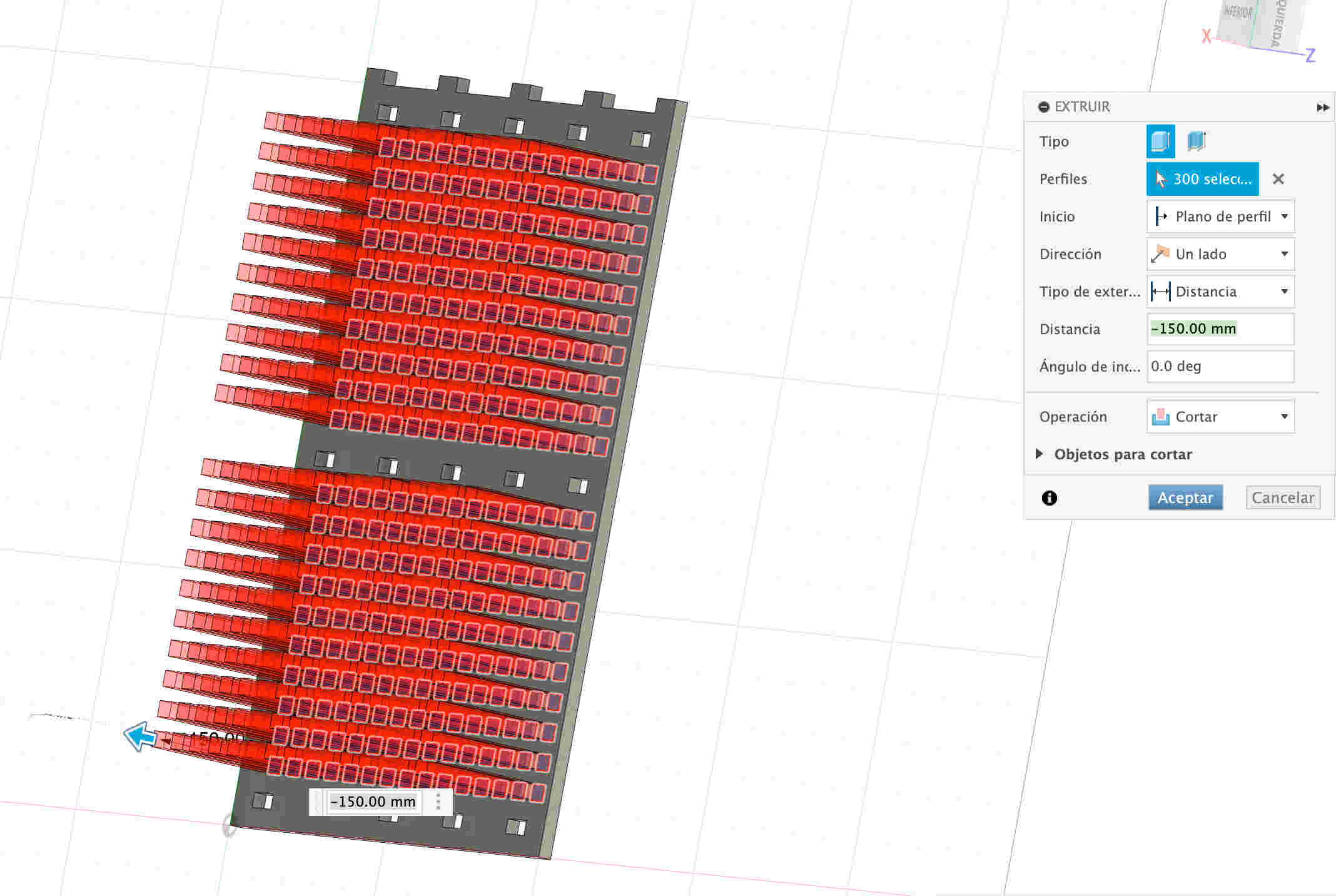
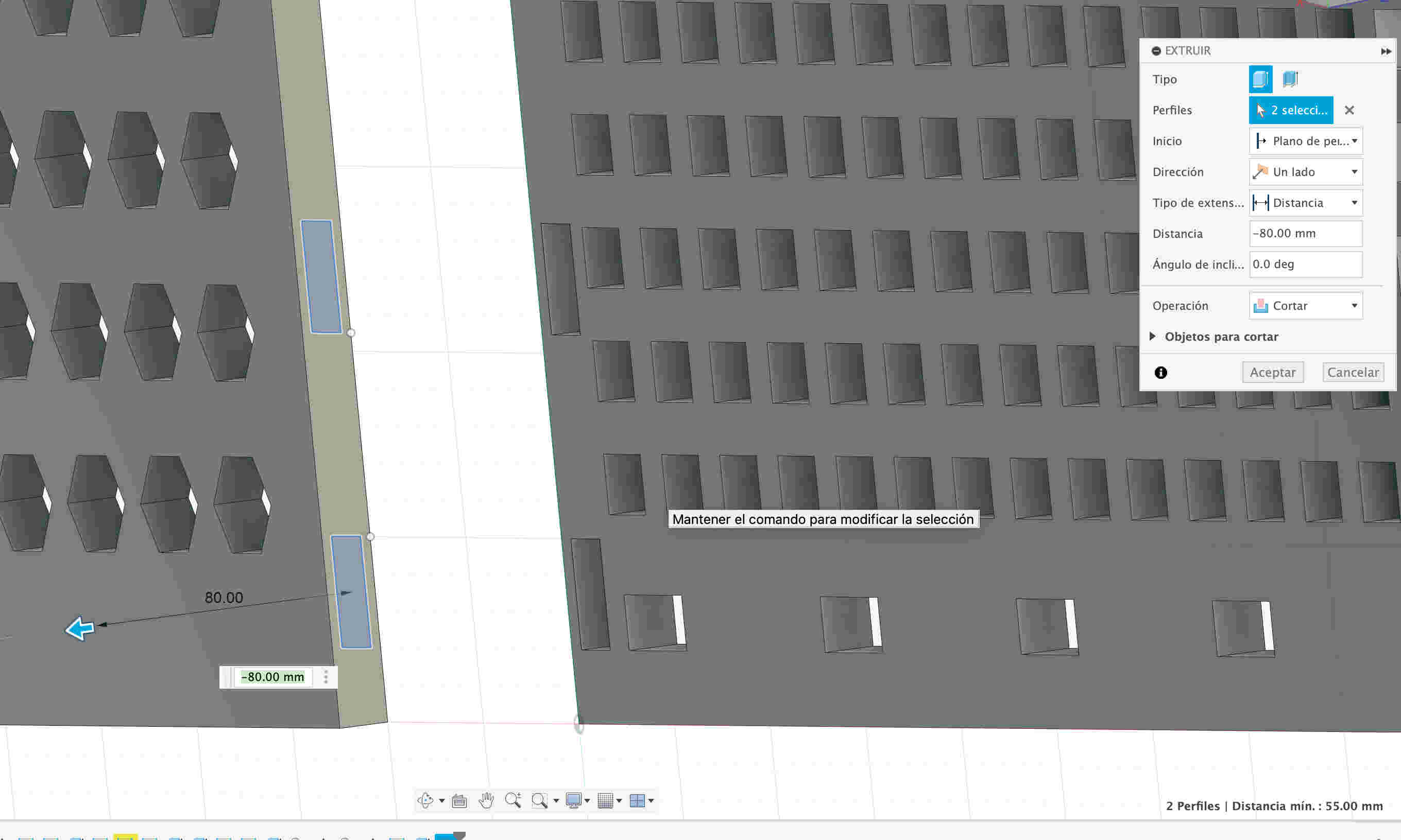
- With the E command you can open the extrude option and set the operation option to cut to make holes in all those matrices and make it have a different appearance

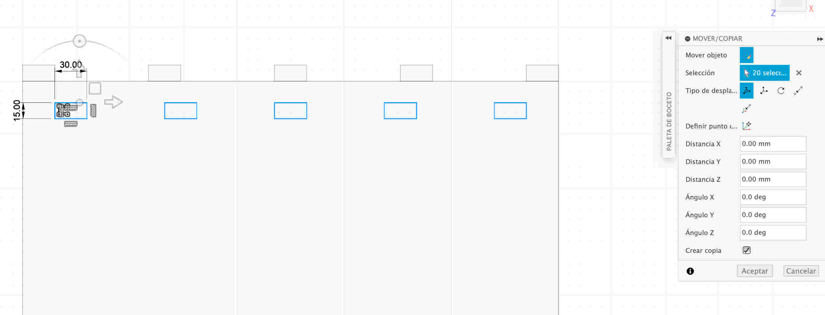
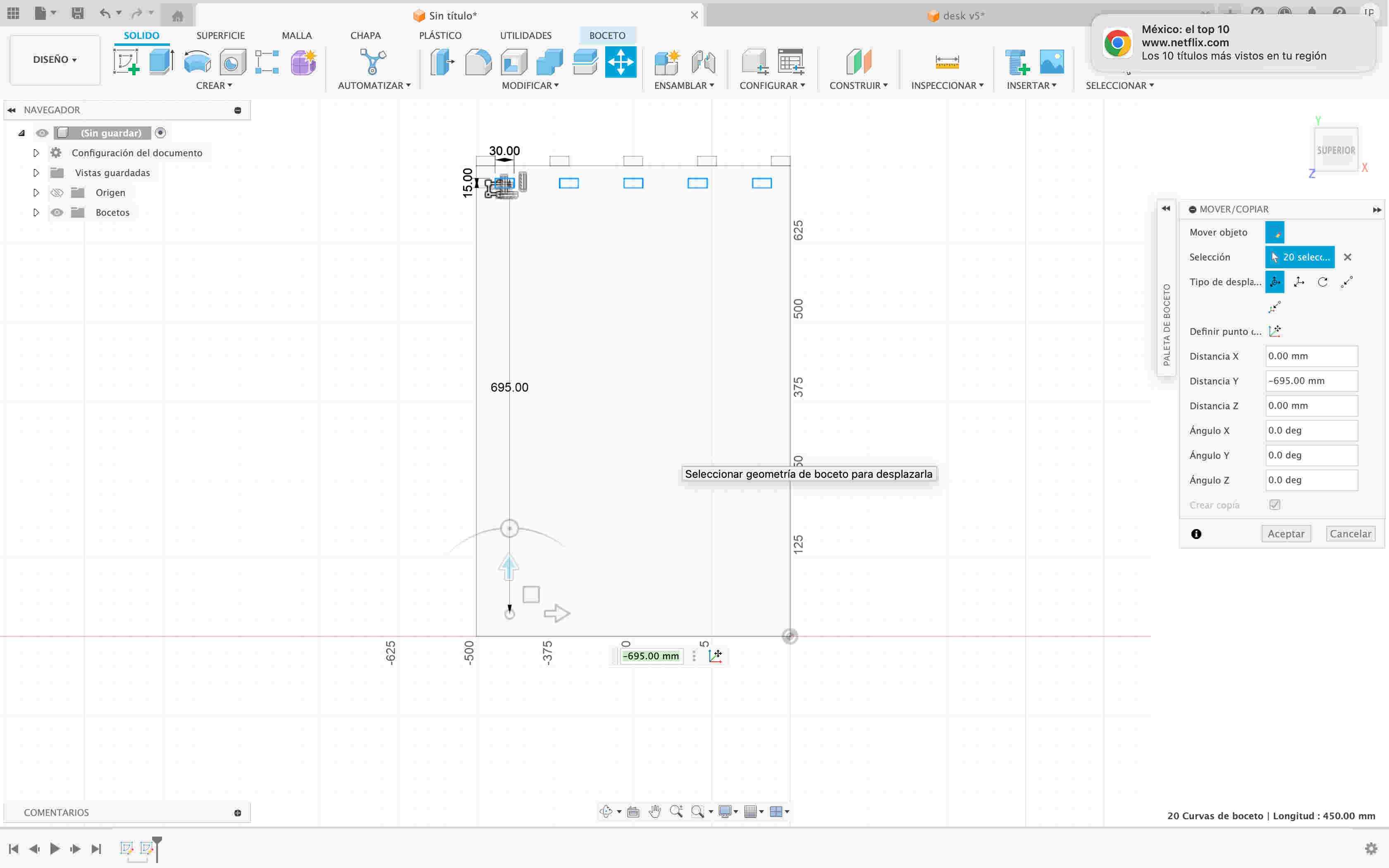
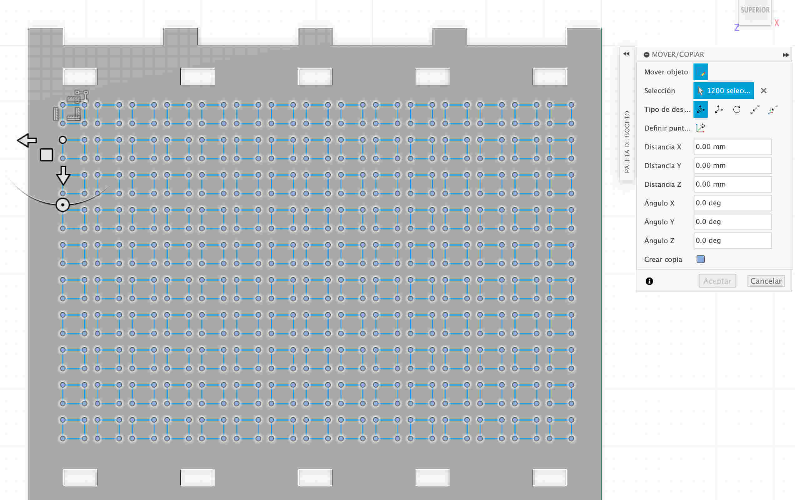
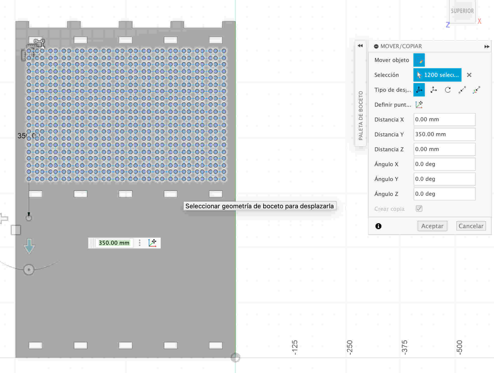
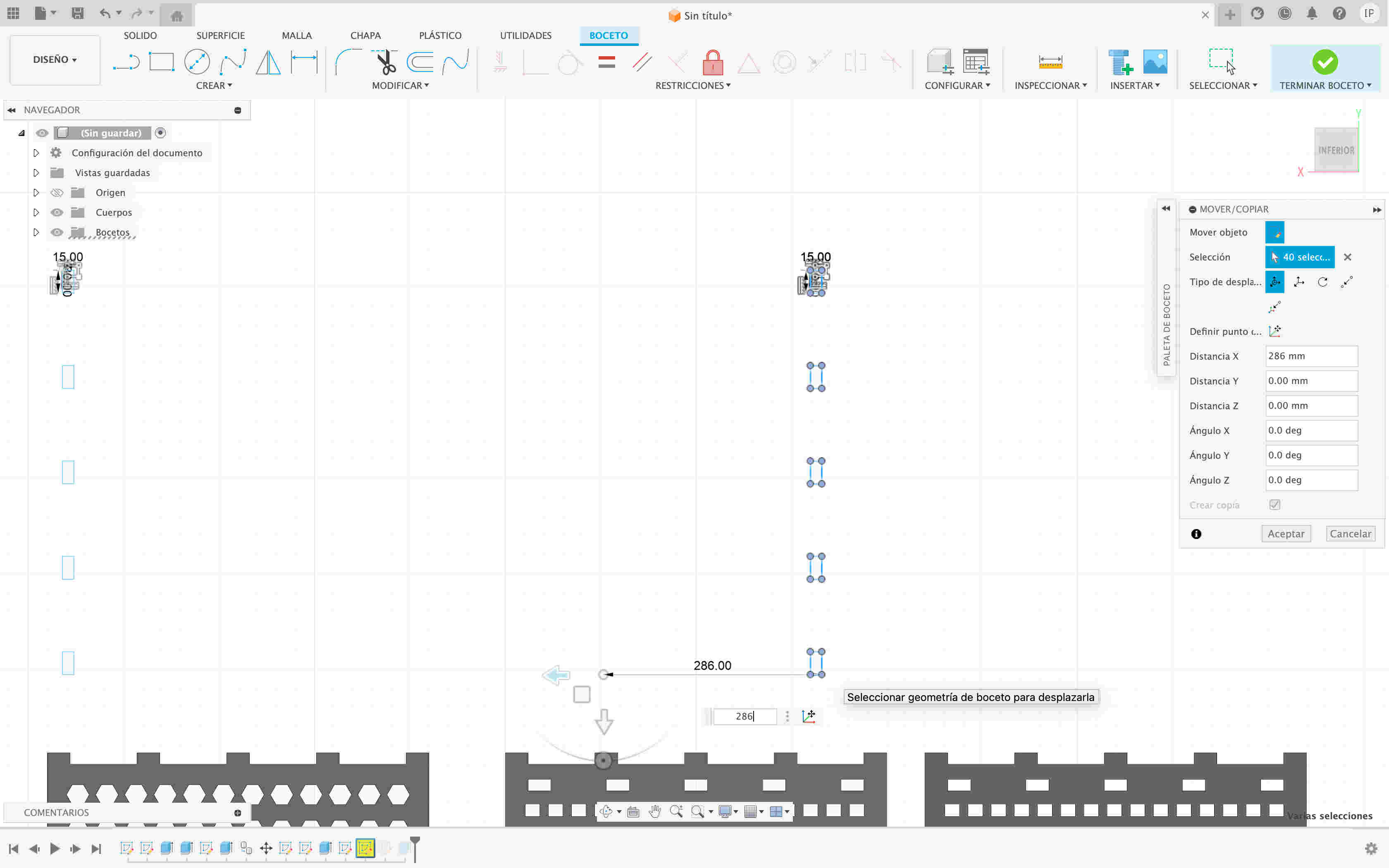
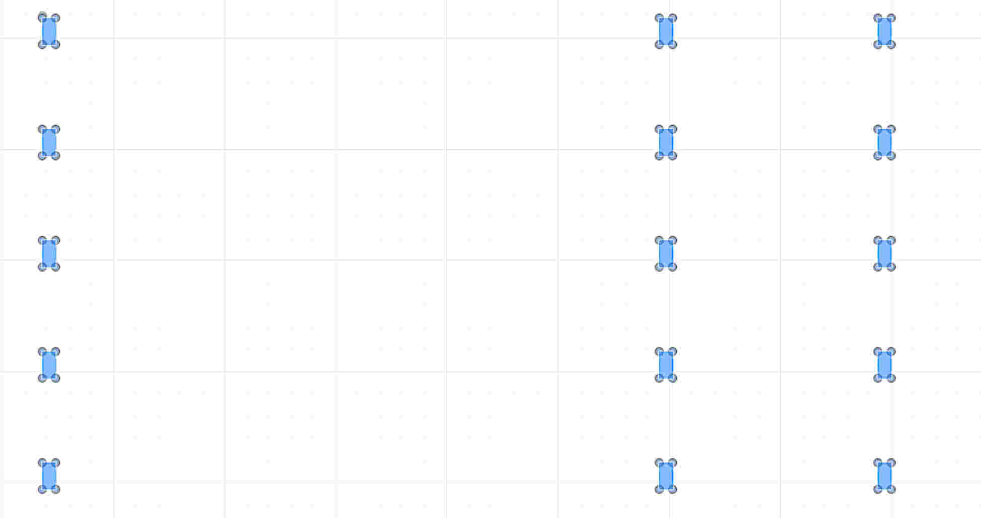
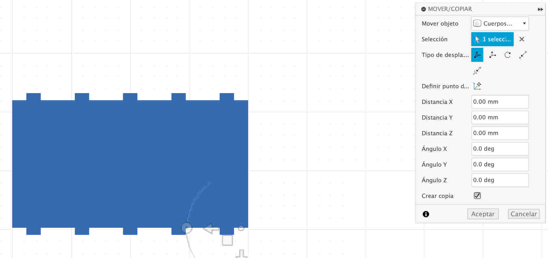
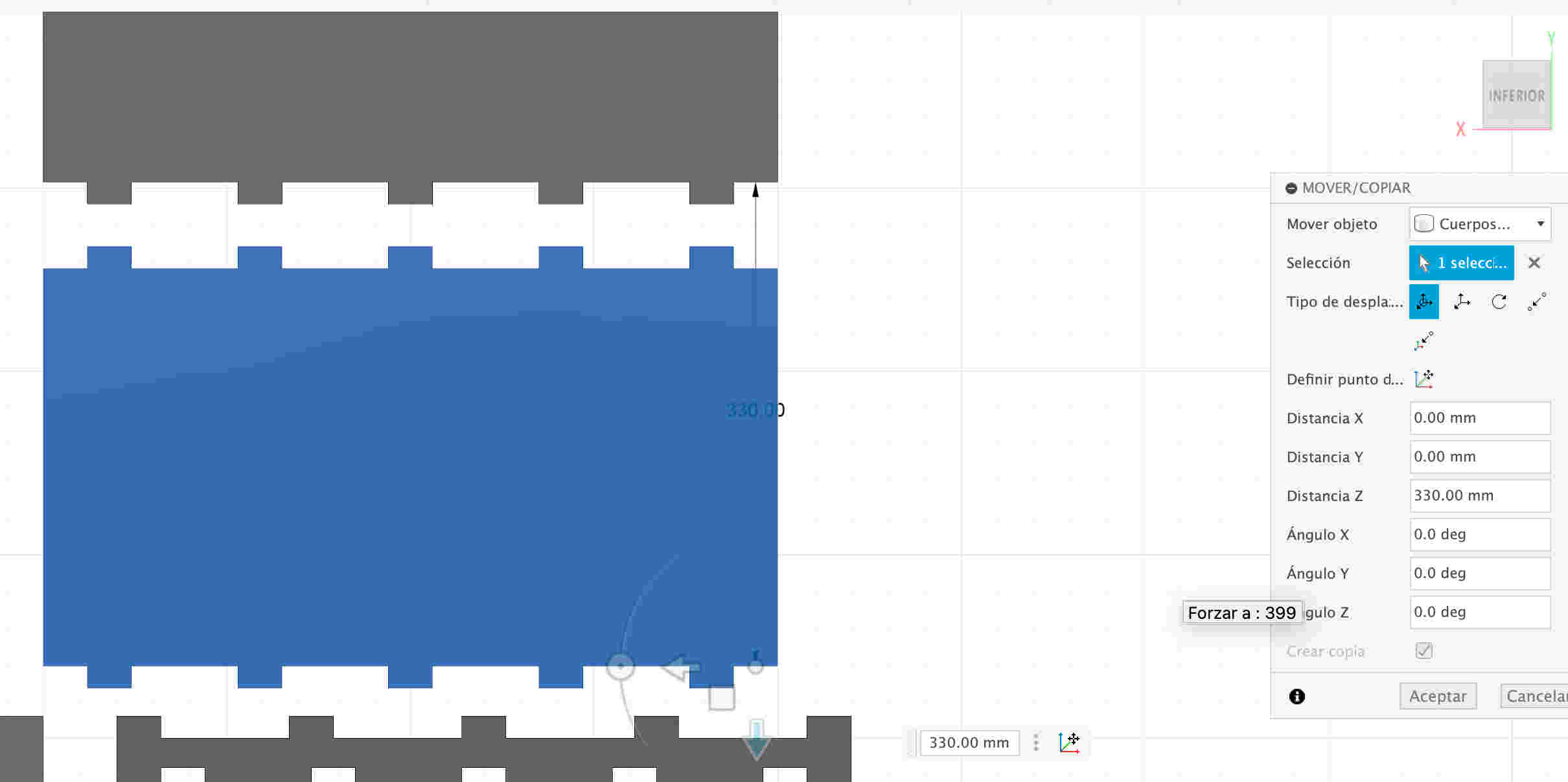
- Pressing the M button will open a tab to move or copy the piece that has just been created. In that tab there is a text that says create a copy so i will click on it to save all the previous steps.


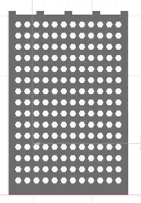
- I will create a new rectangle with the measurements of the previous ones but with a different shape so that it doesn't look so monotonous. I will create a matrix for that specific figure so that it can look symmetrical and be faster to create them
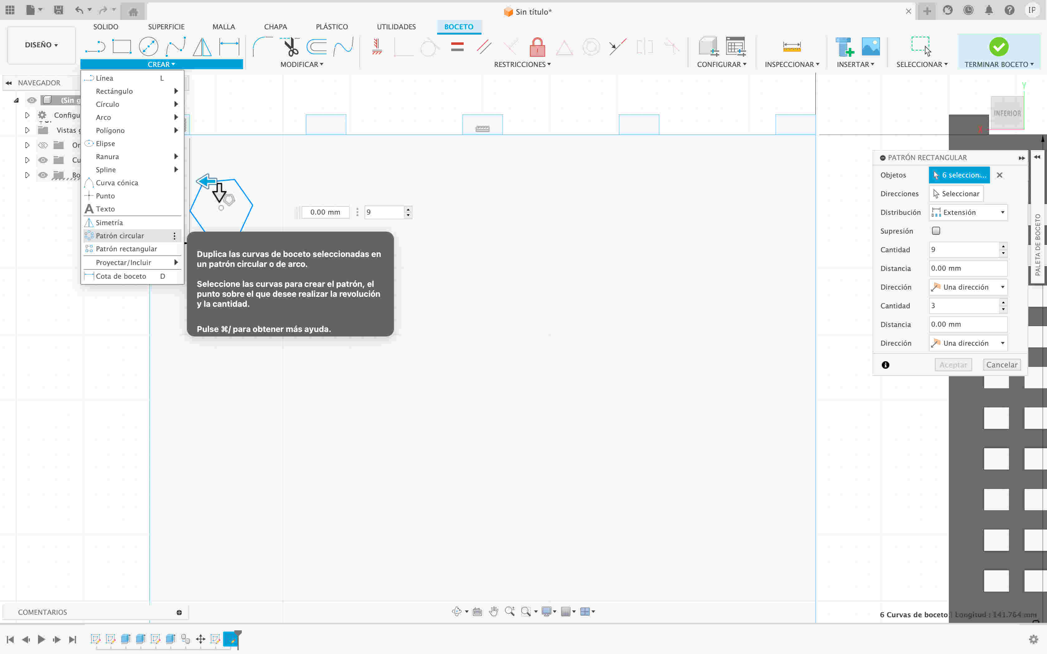
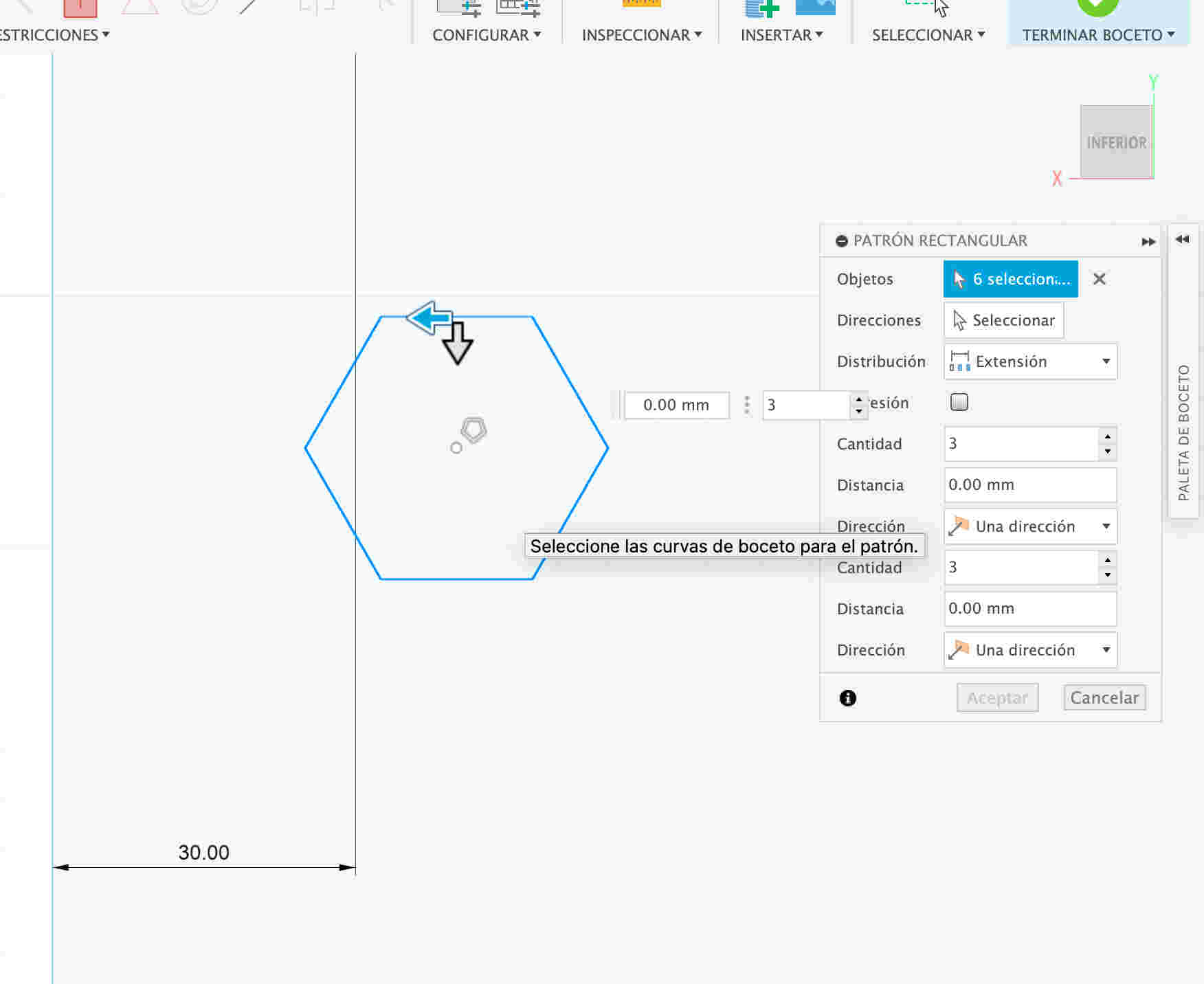

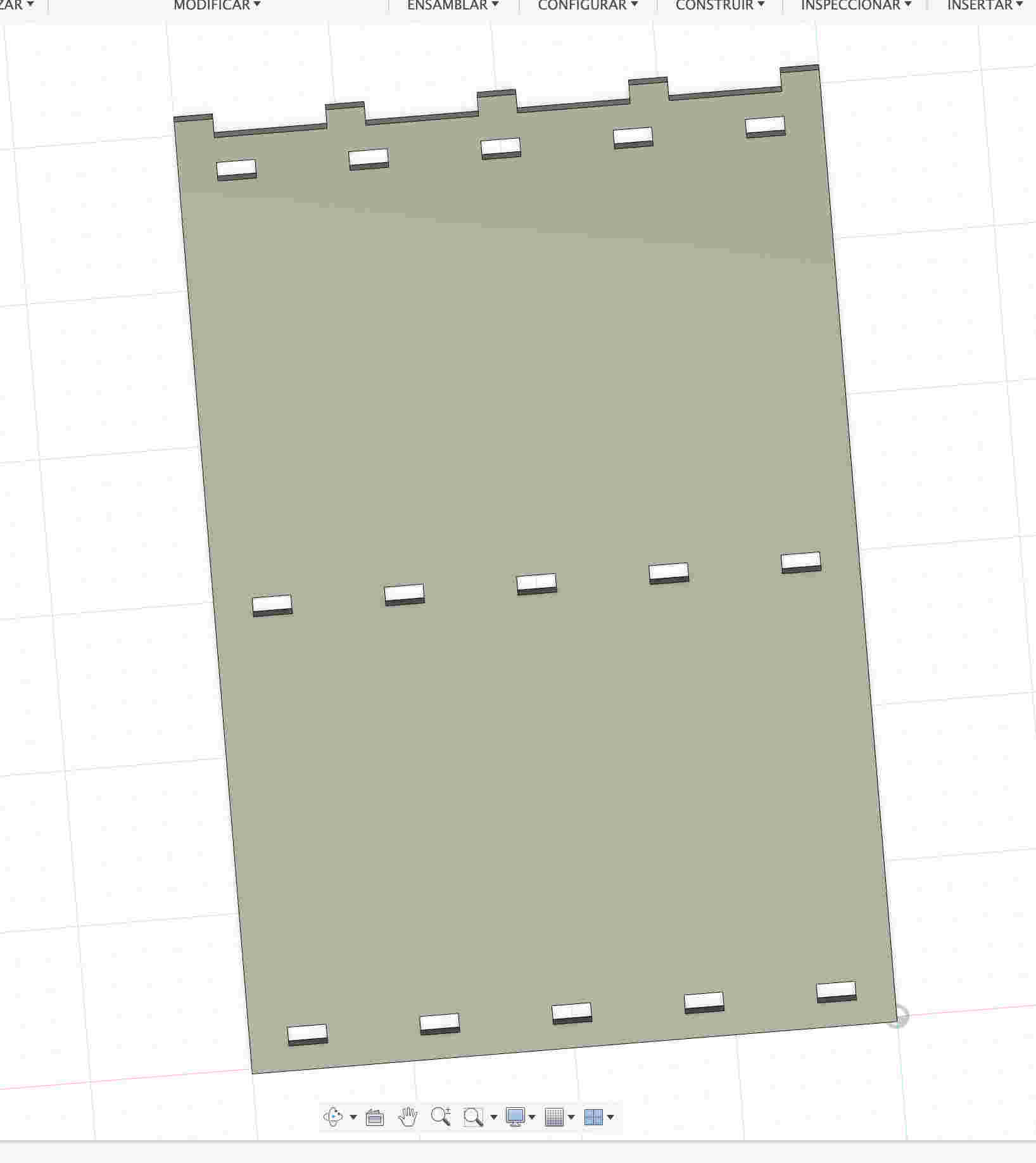
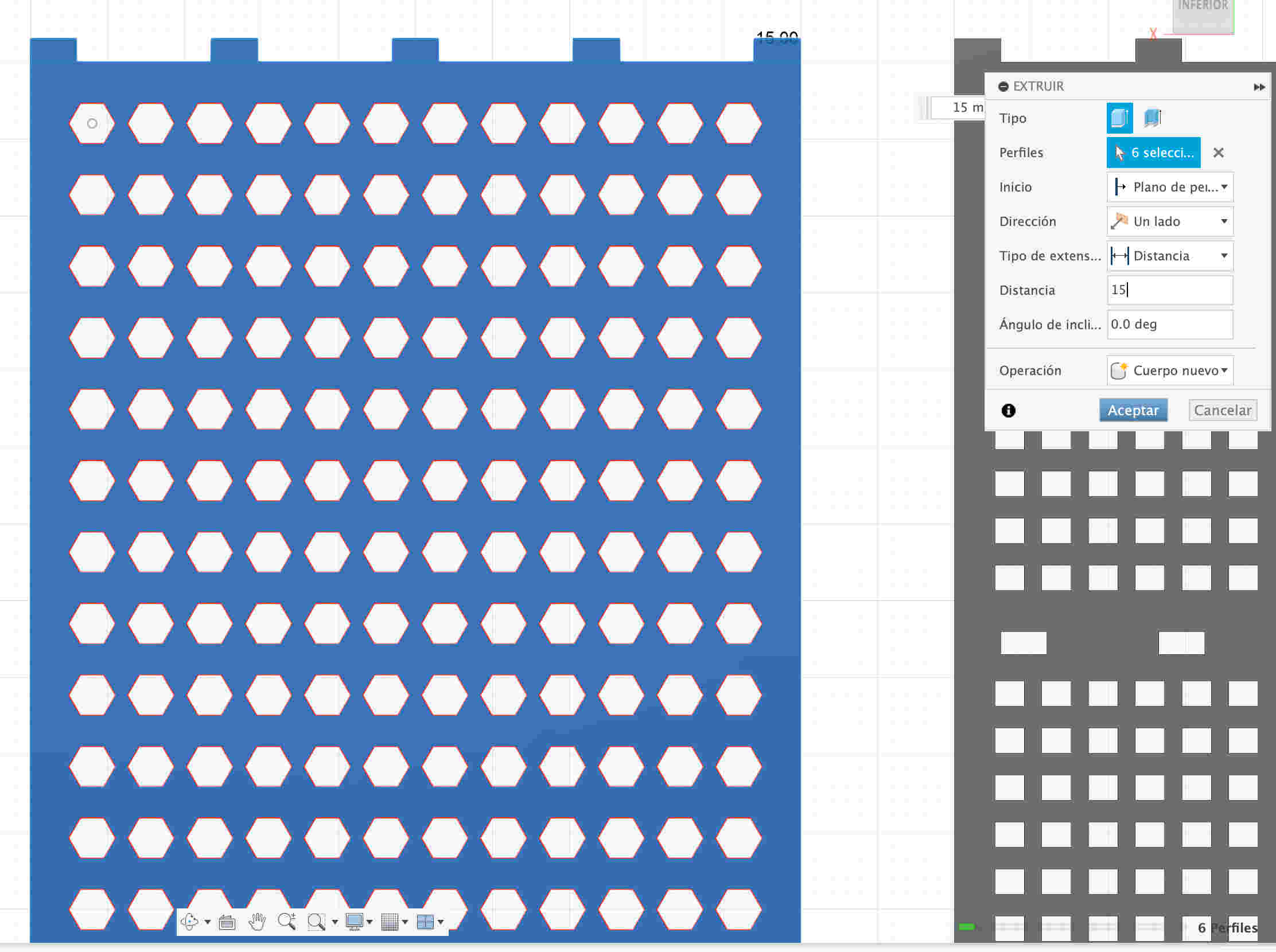
- The E button opens the extrude option, so after that I will extrude the rectangle and this time the hexagons made the hole automatically so this time I won't have to cut them
- I will create a rectangle that will be used to assemble with the supports, I will give it the specific measurements and I will create a small rectangle that will be used to later make a matrix of rectangles to be able to assemble the tabs of the bases

- With the M key I will copy the matrix and change it to where I want to adjust my bases and extrude the rectangles to leave the holes


- Now I will make another rectangle that will serve as shelves, I will do almost the same procedure; I will make some rectangles with a matrix that will be the tabs so that the shelf can be fixed, I will extrude the sketch and copy the shelf with the M command and create copy.


- Cut some rectangles at the bottom so you can assemble the foot support.

- Now I will make a foot support with more rectangles with the same principle as all the others
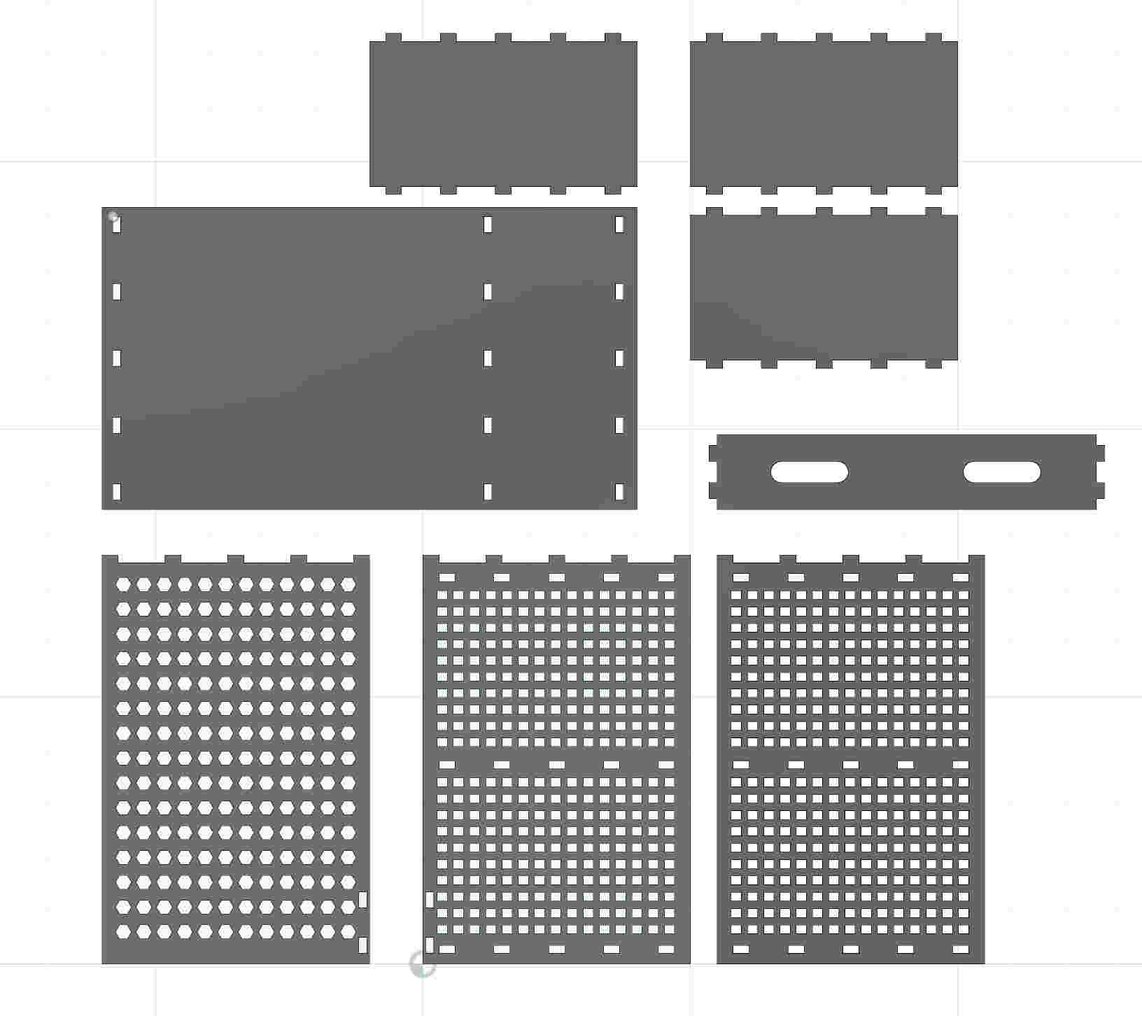
- and this is how all the pieces turned out.
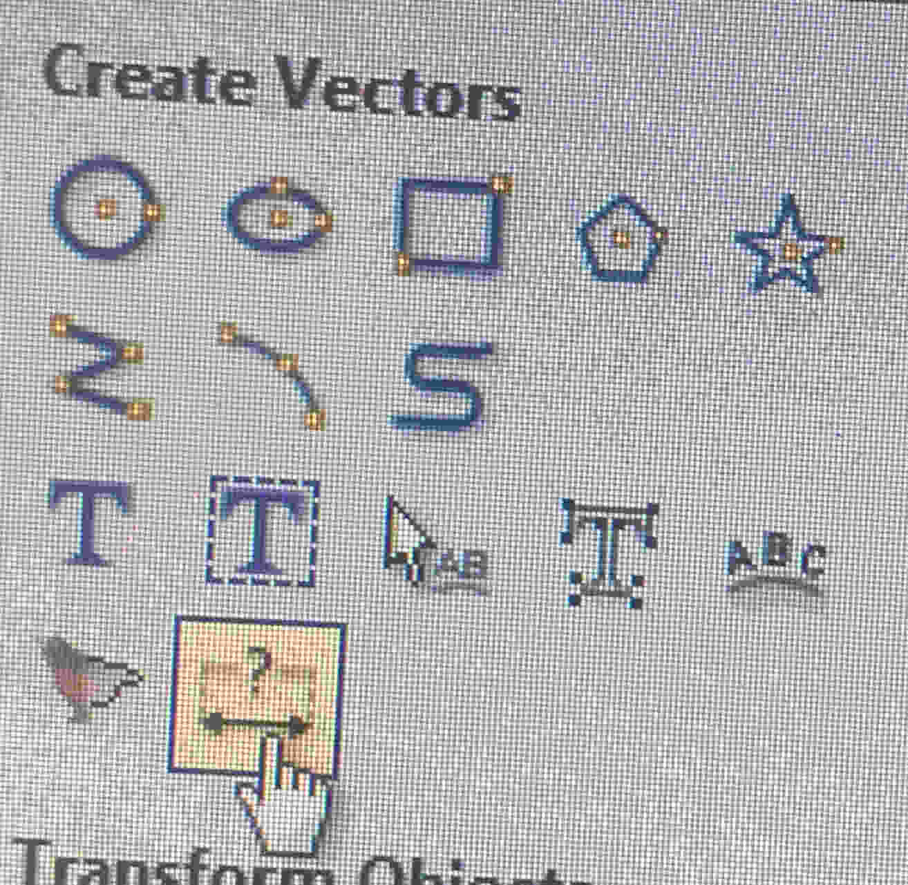
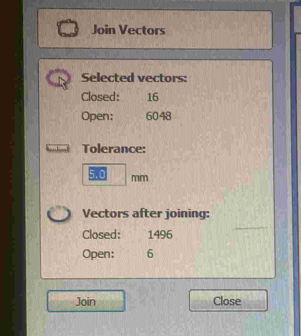
- With the joint/vectors option I will make the figures close if they were not joined
- We will open our file made with the option on the right side of the toolbar


- I will create an appointment to know exactly how much space to leave when cutting and thus be able to correctly size my other pieces.

- I will cut the lines that intersect with my design so that when cutting there is no error in it

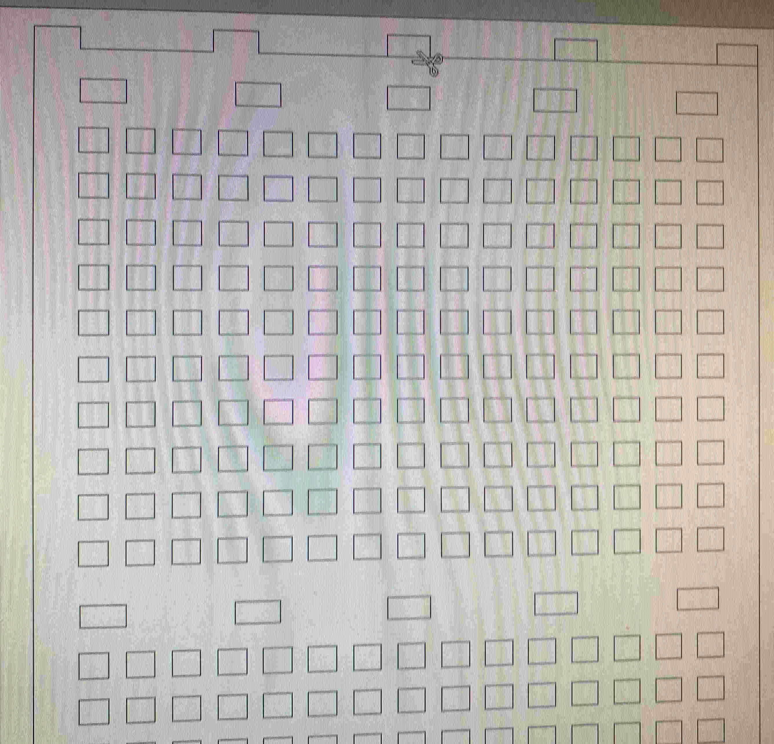
- I will put the tolerance that the machine has, which in my case is 5 mm
- Afterwards I will be looking at the specifications of my tool (right side toolbar, tool tool and edit button) at how many revolutions per minute will my cutter go and which will be 1000 rpm, the feed rate in my case will be 3200 mm/min a plunge rate of 400

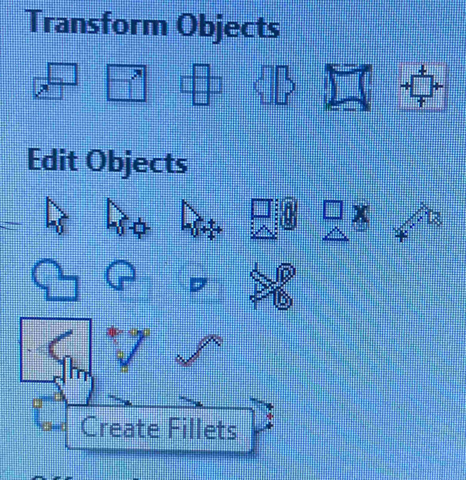
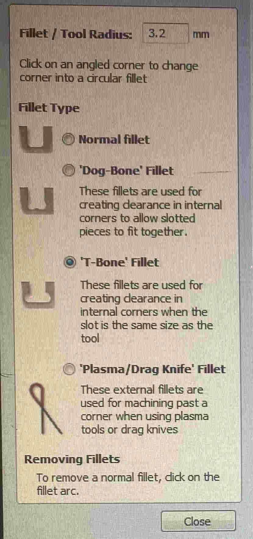
- I will create some fillets for my pieces so that they can be assembled in a simple way. In the edit objects option I will click on the create fillets option. A new tab of options opened for me in which I will choose the T-Bone Fillet option since for me it is the option that best suits my design
- then I choose, I choose part by part where I want my t-bones and dog-bones, it took a long time but in the end that made me realize quite a few errors in my design so I corrected it by deleting the duplicate pieces
- In the tool paths option, specify how deep I want my cut, which I will give a depth of 15.3 mm, specify my tool, which I will use a "6 mm End Mill" and configure Asia to make the cuts by inside and conventional so that you do not make a bad cut and no part of the desk suffers any mishap.
- To finish with the preview toolpaths option I will be able to add material and color, and I will be able to visualize where the machine will start cutting to where it ends, this option will tell me how long it will also take. To finish I will save it in G code
- In order to start cutting it will be necessary to change the tool that I chose in the specifications so that the desktop does not have any defect in which the problem factor could be the cutting tool (I used the V-bit 60deg 6mm)
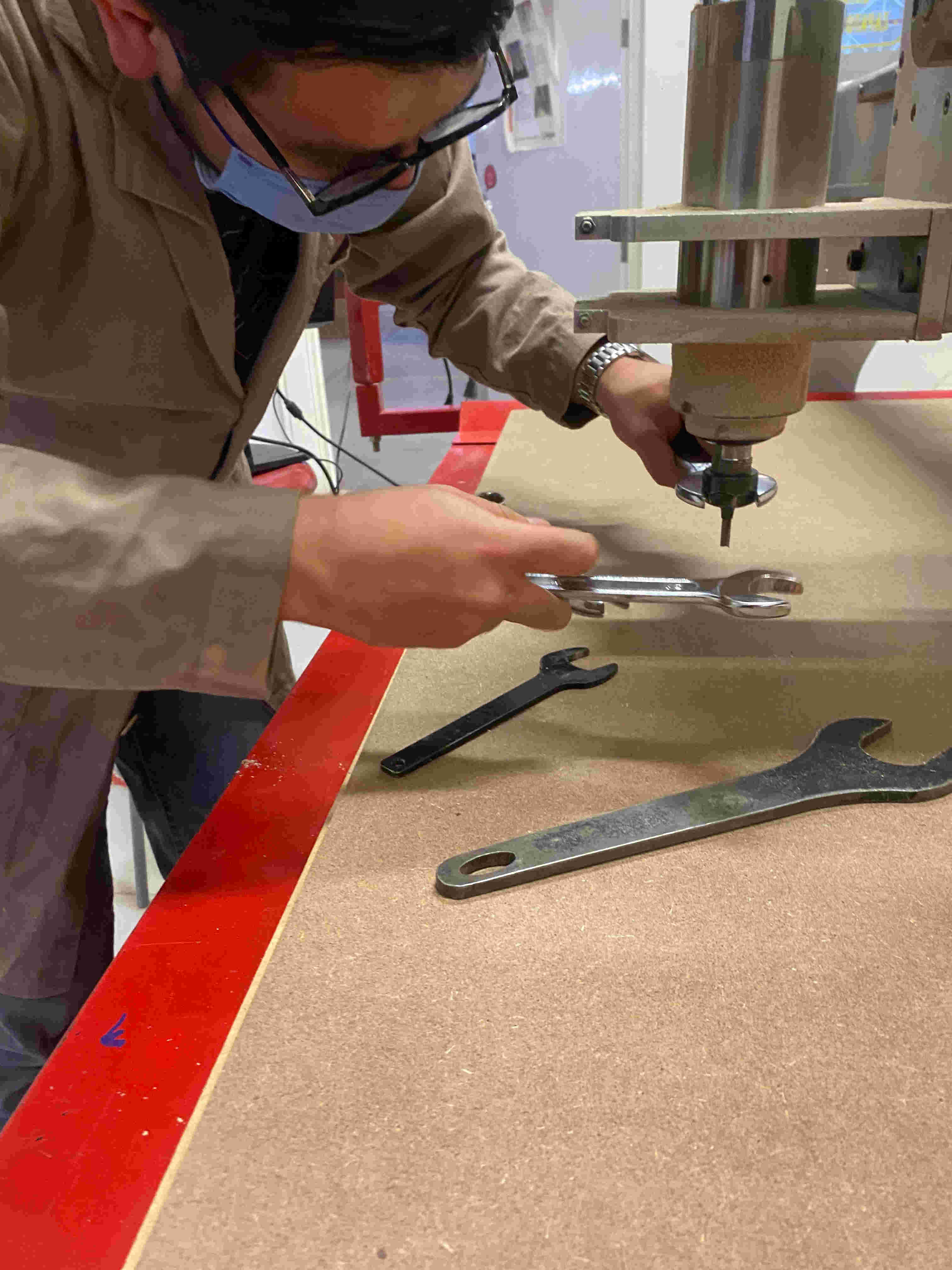
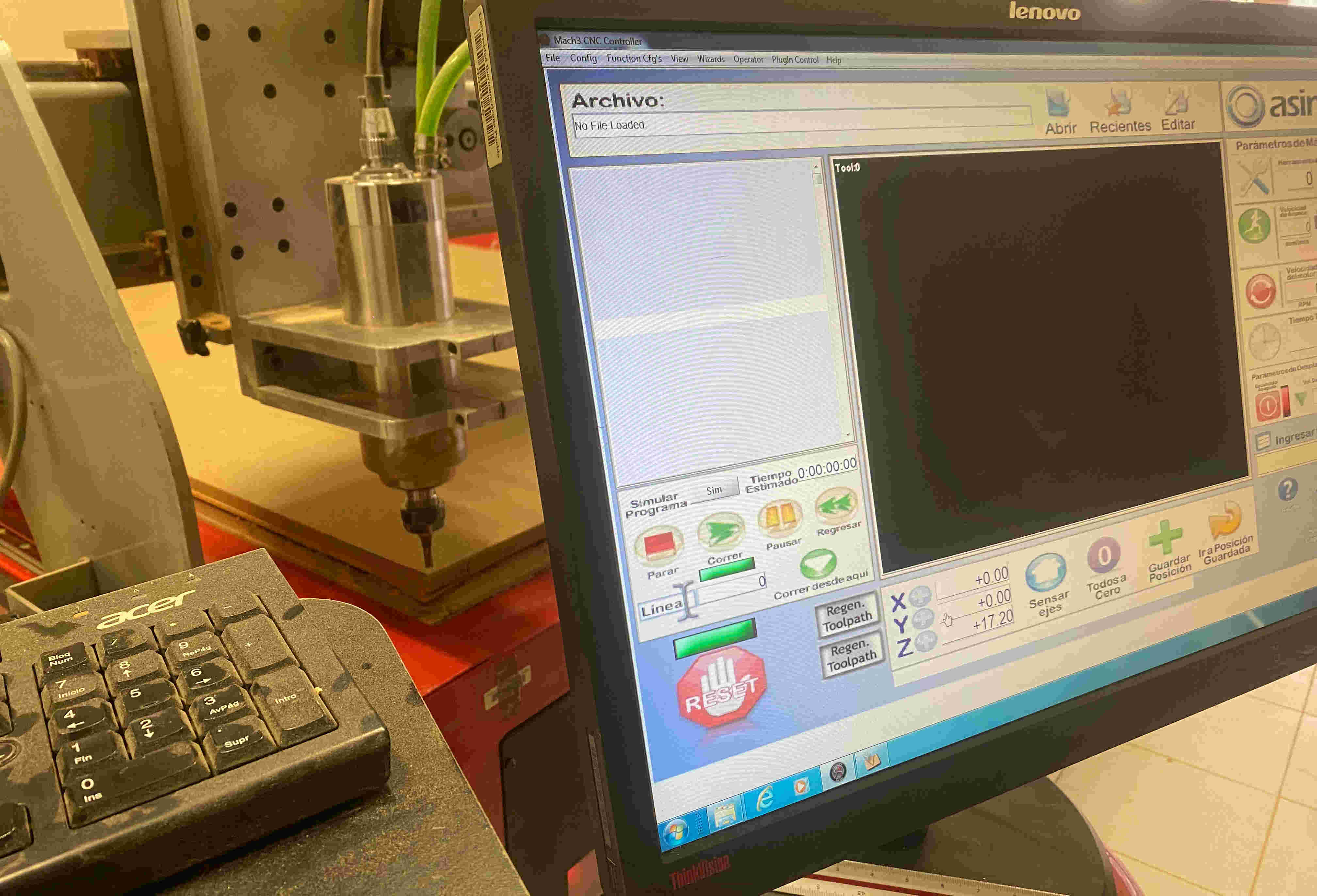
- To start cutting I will open the mach3 CNC controler program to be able to send my G code to Asia, I can place my piece on axis 0 and thus start cutting
- After sending my part to my axis 0 (which will be on the left side of the bottom side) I will have to save my X, Y & Z axes by pressing the + buttons in the software. to start cutting I will click on the run button
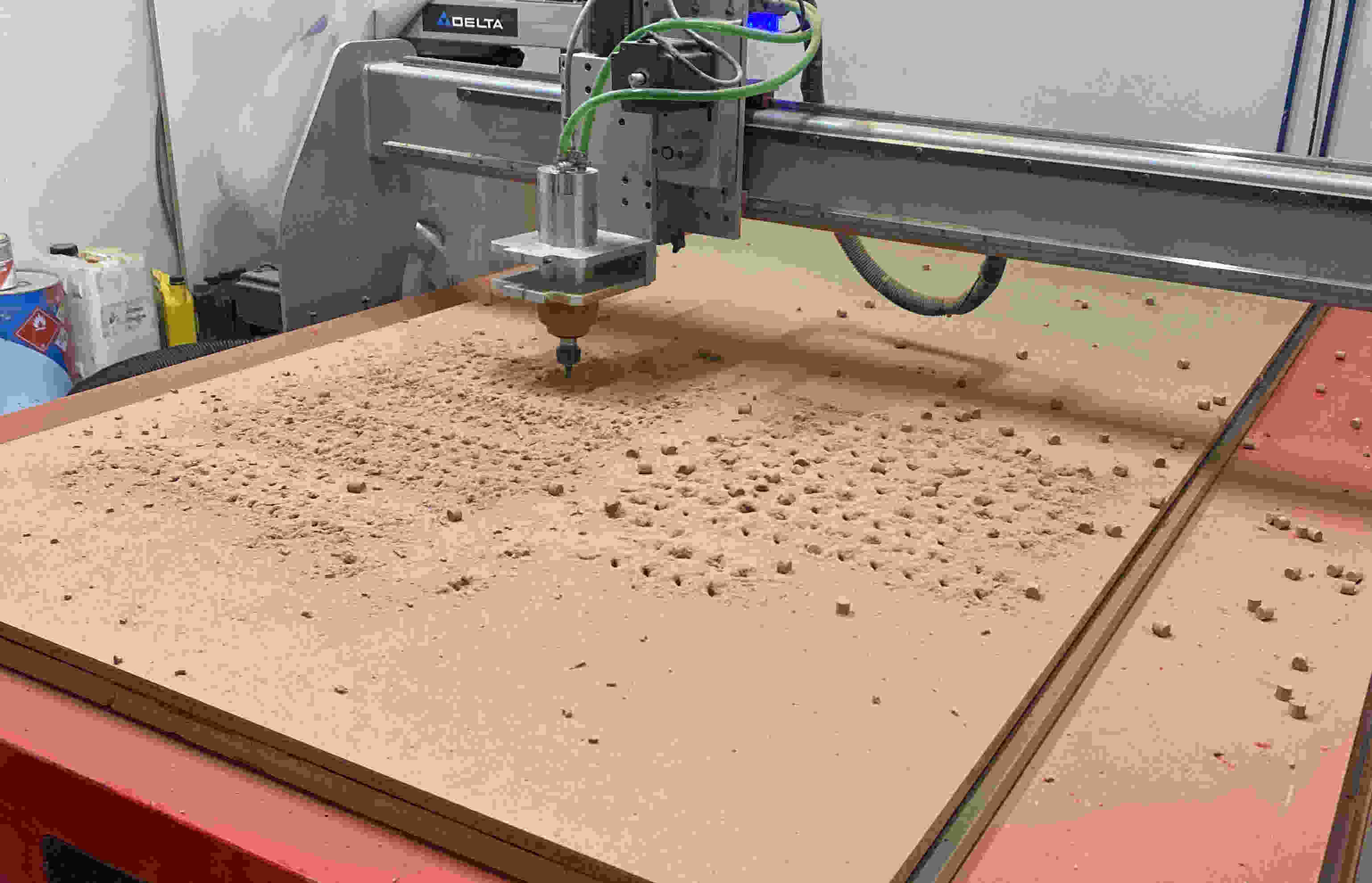
- We just have to wait for them to finish cutting the pieces
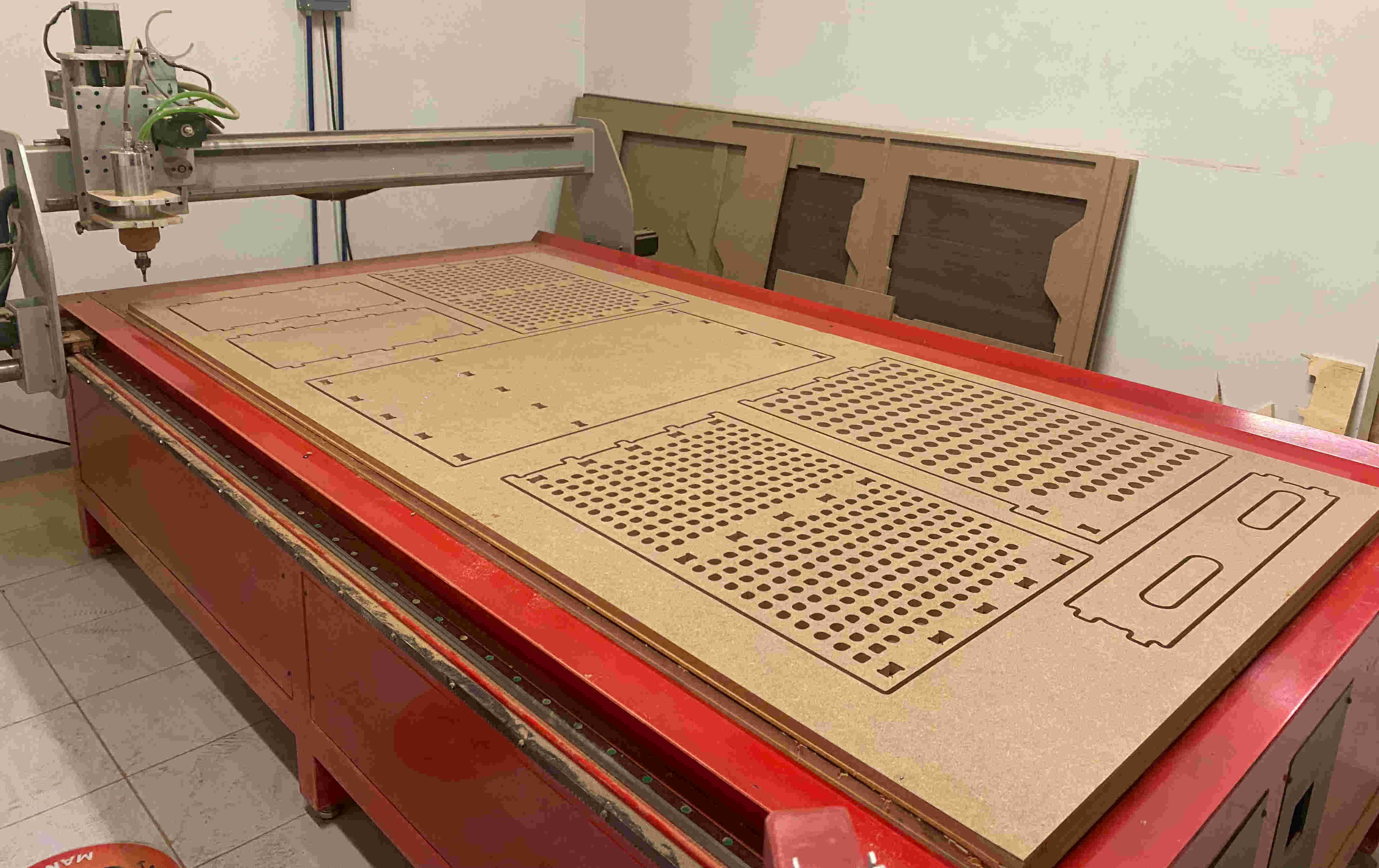
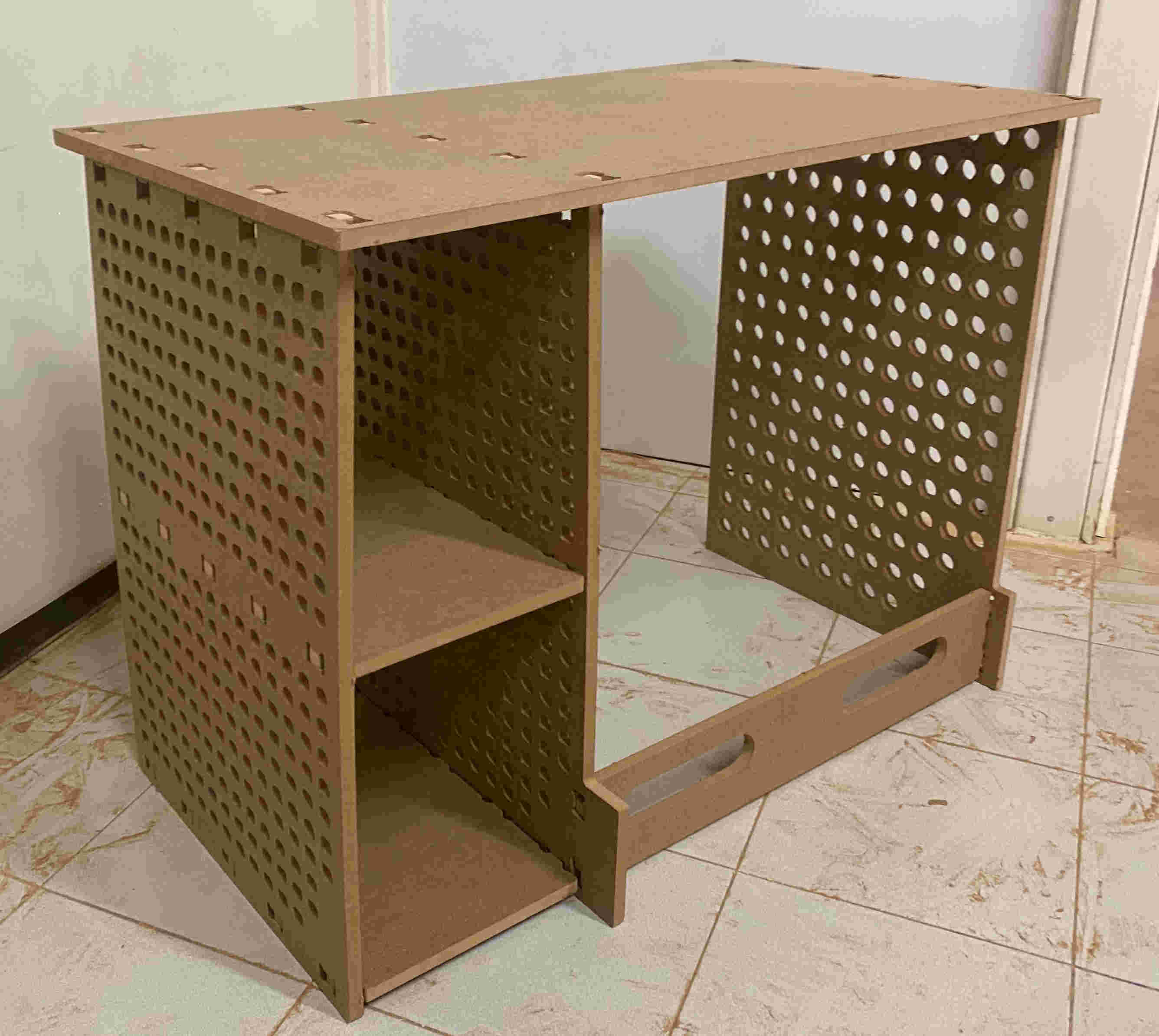
- This was the result of the desktop, apparently nothing went wrong
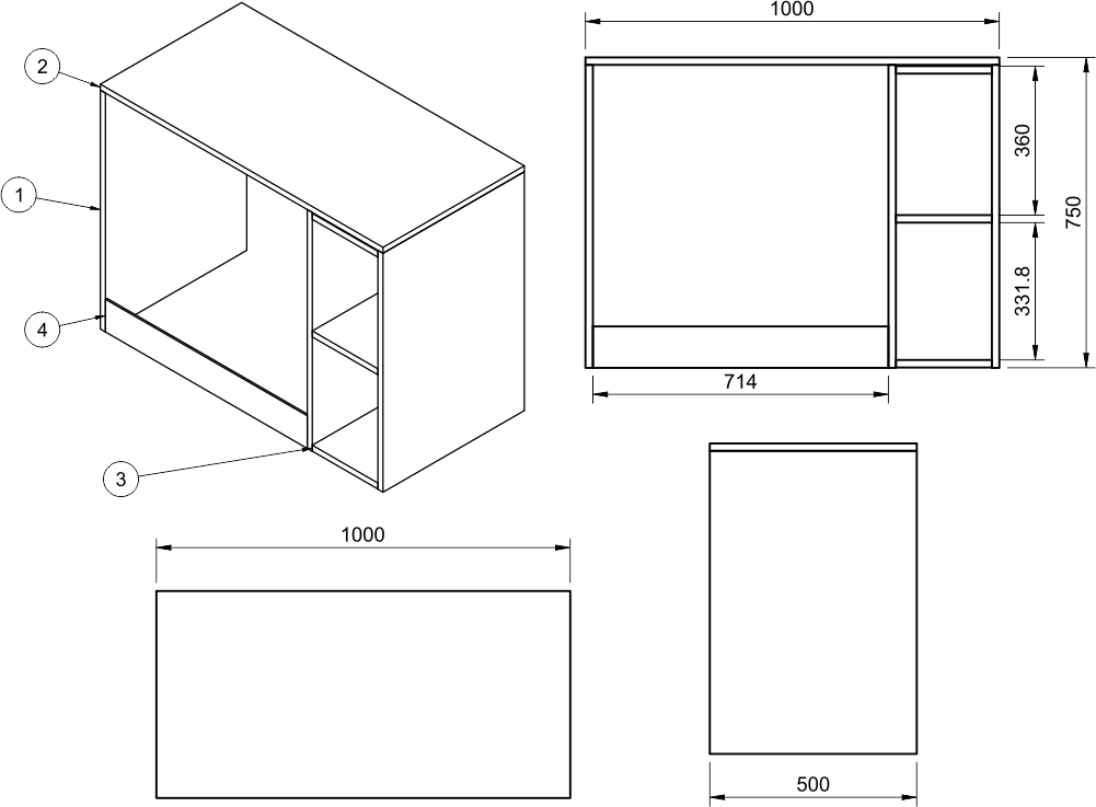
- How to make a desk
- How to make a technical drawing of your desk
Machine
For this assignment we will use the Asia Robotica SHOP 1325 machine.

| Power 4Hp at 24000 RPM's |
| Machine: Generic Made by University |
| Dimensions: 3x1.8x1.7mts |
| Power Supply: 220v/2F/3.5KW |
| Material Fixtures: Nails |
Materials
| ABS |
| Acrylic |
| ALUCOBOND / DIBOND |
| Aluminum |
| Copper |
| Estirene |
| Solid Wood |
| Softwoods |
| Tin |
| Hardwoods |
| Plywood |
| Bakelite |
| PVC (solid/foamed) |
| Polyethylene |
| Solid polycarbonate |
| Non-ferrous metals |
| OSB |
| Nylon |
| Melamine over agglomerate |
| MDF Laminate |
| Veneered MDF |
| MDF | Resins |
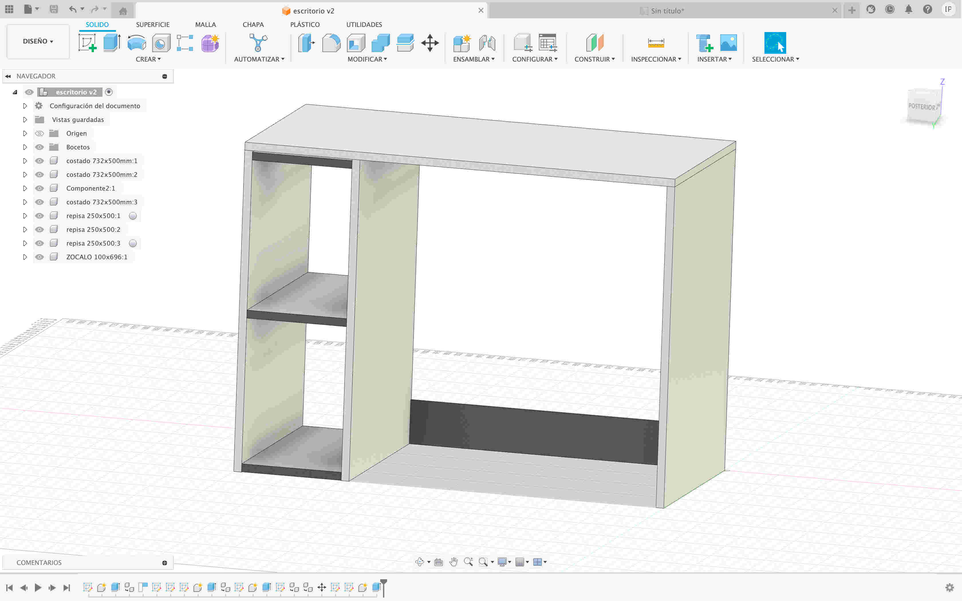
My design
First I thought it would be cool for this week to make a desk because we are working on 15mm mdf. I made my sketch in fusion 360 so I could have an idea of what I wanted to do.
VCARVE
In order to cut our MDF, open the VCARVE program to generate dogbones and tbones which will be used to assemble each component.