10. mechanical design and machine design
In this two weeks we made a CNC in teams, my main functions in the development of the machine were: checking that the step-by-step engines were working well as the controllers and the arduino shield in general, as well as reviewing that each one's designs were consistent with each other, in the end I would say that was the most difficult thing.
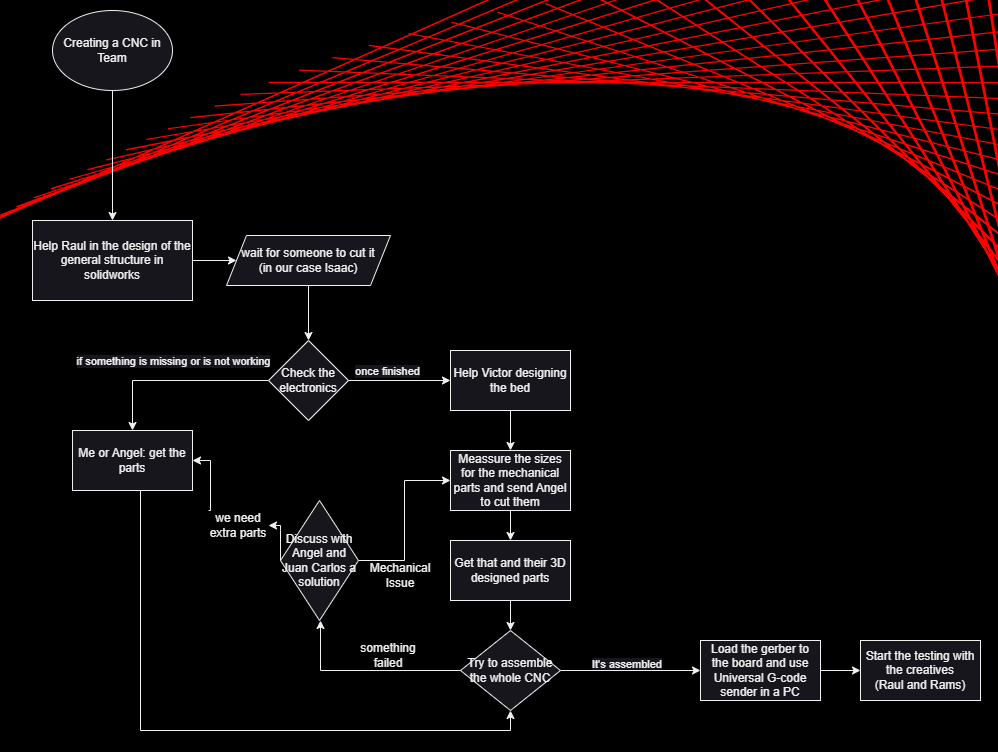
So, to ilustrate the enterity of process I'm creating a diagram to show all the steps in the design, making and colaboration for the cnc.
Testing the Electronics
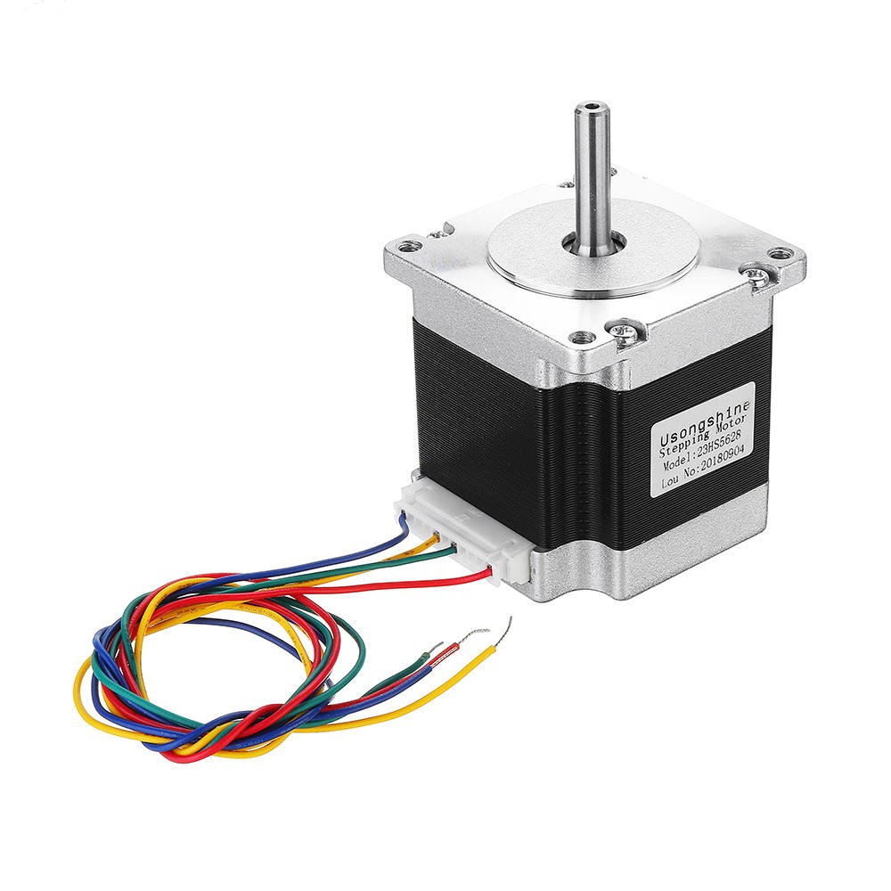
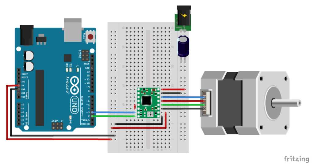
For the project we needed 3 motors to control the axes, and their respective H bridges, then mount the arduino shield on the arducino one, and the components in the positions x, y, z, on the controller.
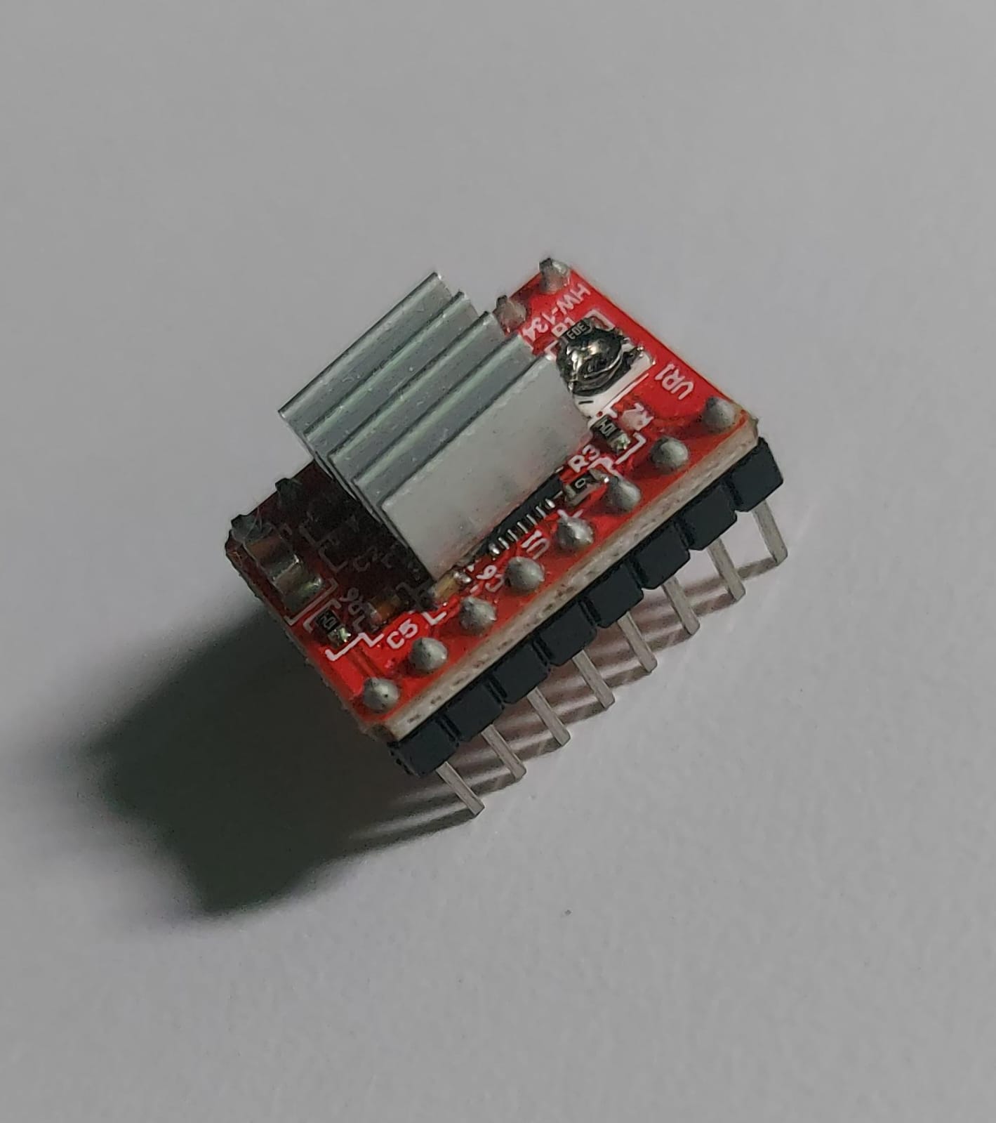
The controller we used for the project is the a4988, and the motors nema 23.
To check the H bridges and motors i build the next diagram, changing one motor or controller at time.
Using the next code you can check every component, also this arduino library is said to be the one when working with stepper motors, it can't work fully by itself it has some dependencies but, it makes the stepper control pretty understandable, you can change the speed using the set.speed function try using the max speed if it's not working at the start.
	/*
	Example sketch to control a stepper motor with A4988 stepper motor driver,
	AccelStepper library and Arduino: continuous rotation.
	More info: https://www.makerguides.com
  */

  // Include the AccelStepper library:
  #include "AccelStepper.h"

  // Define stepper motor connections and motor interface type.
  // Motor interface type must be set to 1 when using a driver
  #define dirPin 2
  #define stepPin 3
  #define motorInterfaceType 1

  // Create a new instance of the AccelStepper class:
  AccelStepper stepper = AccelStepper(motorInterfaceType, stepPin, dirPin);

  void setup() {
	// Set the maximum speed in steps per second:
	stepper.setMaxSpeed(1000);
  }

  void loop() {
	// Set the speed in steps per second:
	stepper.setSpeed(400);
	// Step the motor with a constant speed as set by setSpeed():
	stepper.runSpeed();
				  }
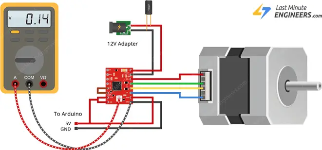
The fist controller, which is also the one of the photo, didn't work, the first and only step you need to try is to check the Current limit formula while moving the nut in the middle of the controller, To calculate it use the next formula: Current Limit = Vref ÷ (8 × Rcs).
When using the driver in full-step mode, the current through each coil is limited to approximately 70% of the set current limit. This means that you would need to set the current limit 40% higher or 1.4 A in full-step mode. When using microstepping, the formula above applies.
That being said you need to alter the diagram and include a multimeter, or a osciloscope if you have it to be 200% sure, another thing to consider is that The A4988 driver IC has a maximum current rating of 2 A per coil, but without a heat sink it can only supply about 1 A per coil before it starts to overheat.
-
The diagram needed to check the reference volatage, you can check the volatage of every circuit in paralell just touching between here and there without remorses.
-
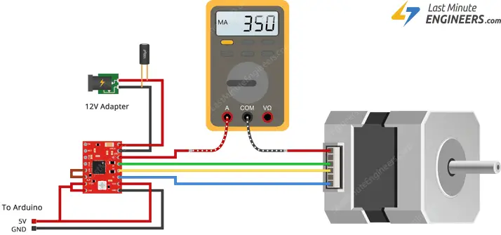
The diagram needed to check the current limit, remmember you can't check current without making a serial electrical connection as the internal multimeter fuse will blow up, be careful please!.
In total 2 controllers were damaged, For the first we theorize that the heat dissipator was wrongly placed and therefore could have entered short circuit, while for the second the nut came of, it does not seem to have damage but is very sensitive.
Another issue during the Electronics production was that we missed one of the cables of a step-by-step motor, we assumed classic dupont cables were able to handle the power needed, so we bought another motor that came with it's cable but you can easily make the cables with some copper.
Installing gerber
To use an arduino or a powerfull enough microcontroller to recognize gcode you can use the grbl program ( repository for arduino uno, nano and micro: grbl github) and a software like universal gcode sender ( Download gcode sender).
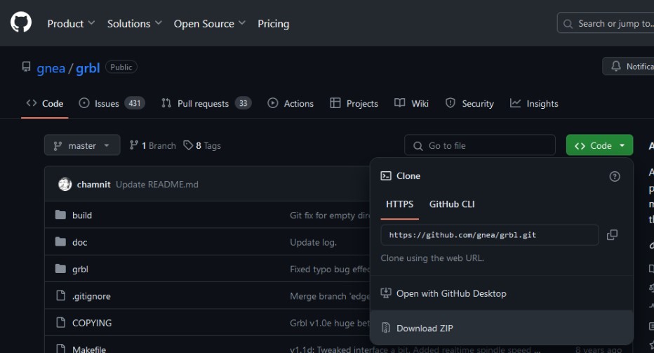
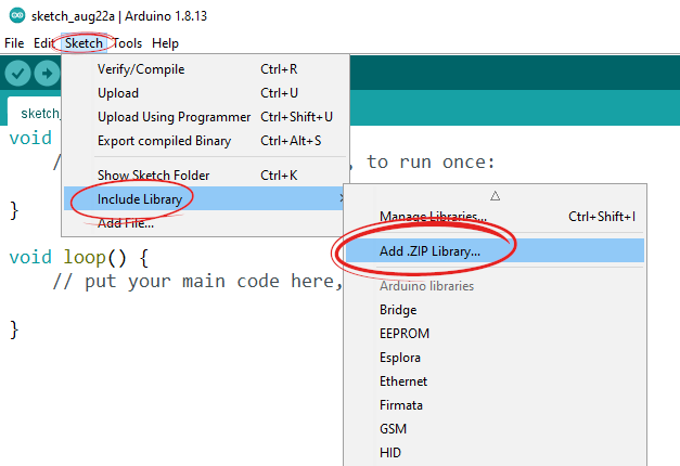
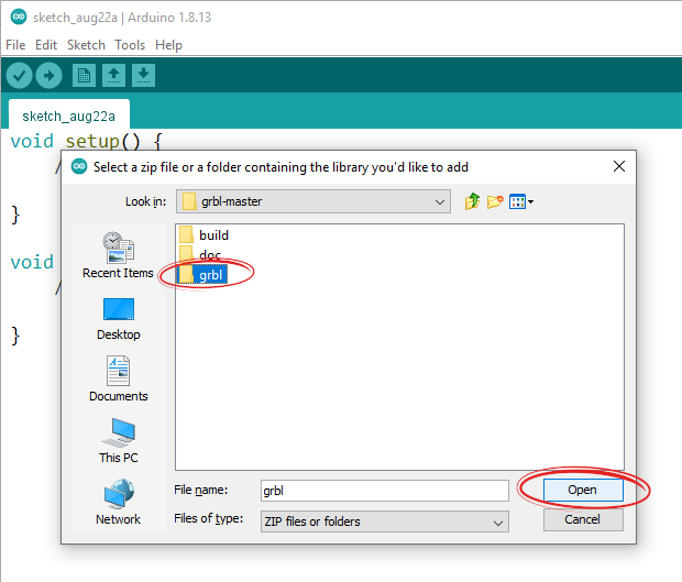
Once you have downloaded all the zip you need to unzip it and add the grbl folder alone into the arduino ide libraries, then in the examples a grbl example will show up, open it and load it to your arduino.
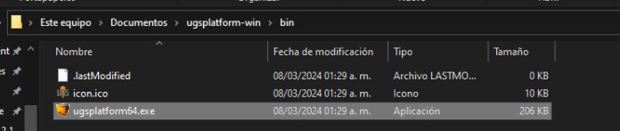
To acces the universal gcode sender you will need, once installed, to follow the next path.
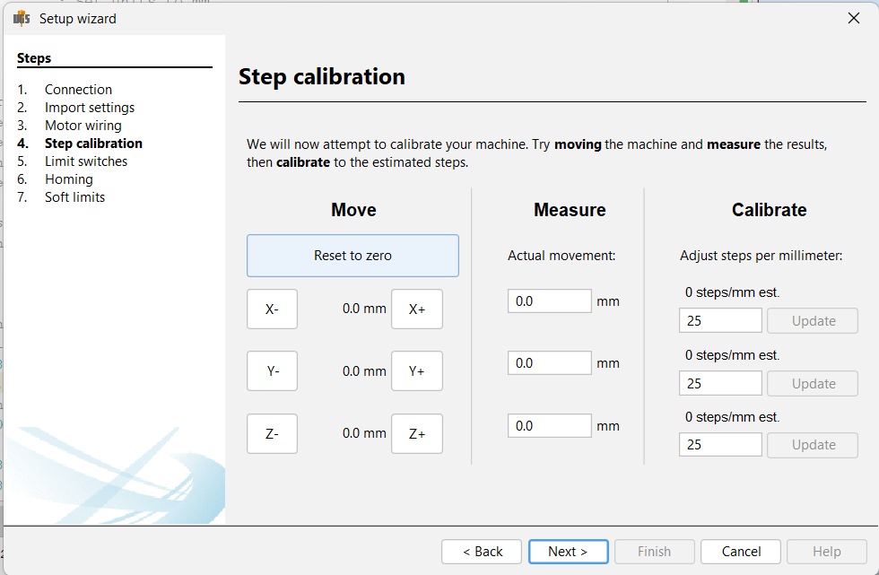
Now in the program go to the setup wizard, there we need to calibrate the steppers, to do so i put the axes near to it's end take a meassure and push the button in the window, then checked how much or little they moved and type it in the second column(meassure), then the program will say a number in the thrid column copy it and type it just in the bellow box and click update, that process for each axis and you should be done.
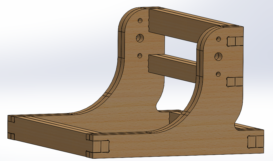
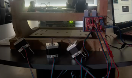
assembling the machine
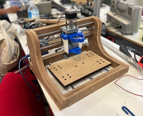
as I mentioned earlier the great difficulty of this machine was to give tasks to everyone since there were not many in fact, so joining the parts required several adjustments, for the base the size of the coupling and its hole was quite inaccurate and then the engine moved to another different position, the necessary screws were absurd as they had to be at least 55mm and it was enough to get them with a width of m3, the bed could not arm it right and the screws would be hidden, my team had to go to cut all the aluminium screws and tubes 2 times because they did not measure well, we had to put legs to the support because a motor became small and many other decisions that proved exhausting to me.