6. Embedded Programming
That's how we call the programms dedicated to the management of the microcontroller. For this week, we must use different languages with the translation of the same code with the aim of comparing their efficiency.
The other task requires understanding the characteristics of microcontrollers working in group, the complete documentation is found at the fablab Puebla page.
-
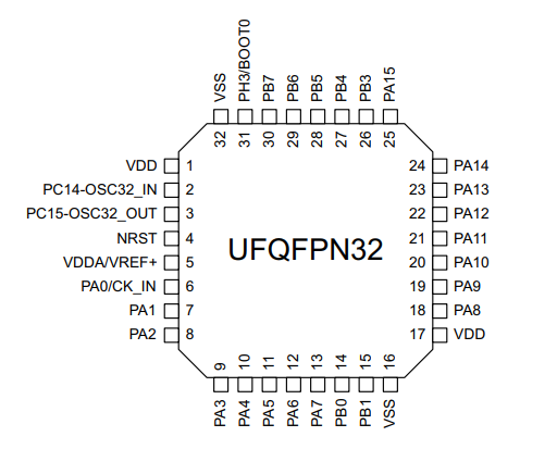
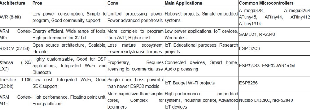
Architecture of the processor
Unlike today's 64-bit computing, due to its size and necessity, up to 32 bits are used, the list show the most common and it's characteristics.


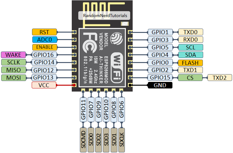
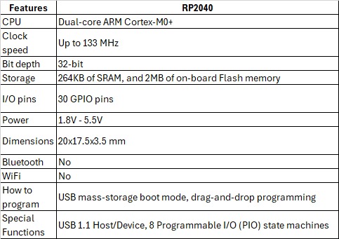
Special parts
There are microcontrollers that have dedicated parts to help with their purpose, like build in wifi or bluetooth, different ports and expanded memory, here is the seeed studio rp2040 datasheet, from there we can see no native wireless technologies but a decent amount of 2MB memory, a decent clock speed built in 32-bit, checking with the multimeter around 3.3V.
-
The languages
As in the previous week 4 we will using the Arduino IDE editor for it's own language based in C++, the new addition to the team is the Mu editor specialized in Circuit/Micro-Python based.
Here you have the link to download the arduino controller software and the new Mu editor.
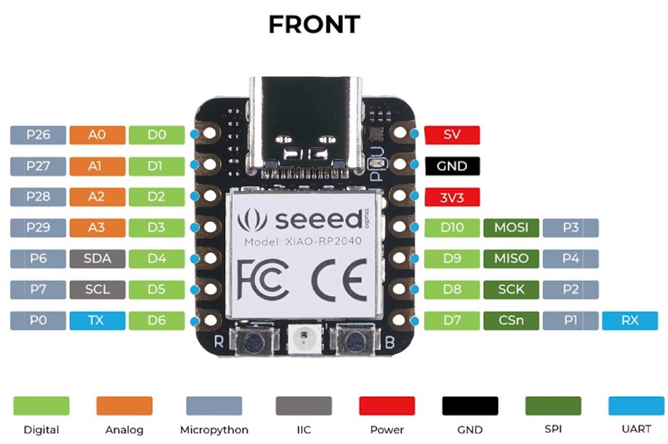
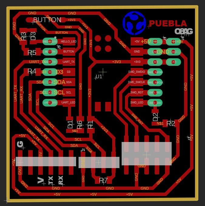
Assignation of pins
With the installation of a microcontroller Programming language the pins get a number assigned in order to interact with them, it's not recommended but if there's a need you can reassign them, in the image you can see the different numbering for each language, the common ground and energy supply, when working in circuitpython there are some usefull codes in the terminal:
import board and then dir(board) to see the available components and numeration, ex.: ['__class__', '__name__', 'A0', 'A1', 'A2', 'A3', 'D0', 'D1', 'D10', 'D2', 'D3', 'D4', 'D5', 'D6', 'D7', 'D8', 'D9', 'I2C', 'LED', 'LED_BLUE', 'LED_GREEN', 'LED_RED', 'MISO', 'MOSI', 'NEOPIXEL', 'NEOPIXEL_POWER', 'RX', 'SCK', 'SCL', 'SDA', 'SPI', 'TX', 'UART', 'board_id']
help("modules") to see the libraries saved in the microcontroller memory, this serves to have a clear idea of the libraries installed and when working with different languages or architectures to be able to compare.
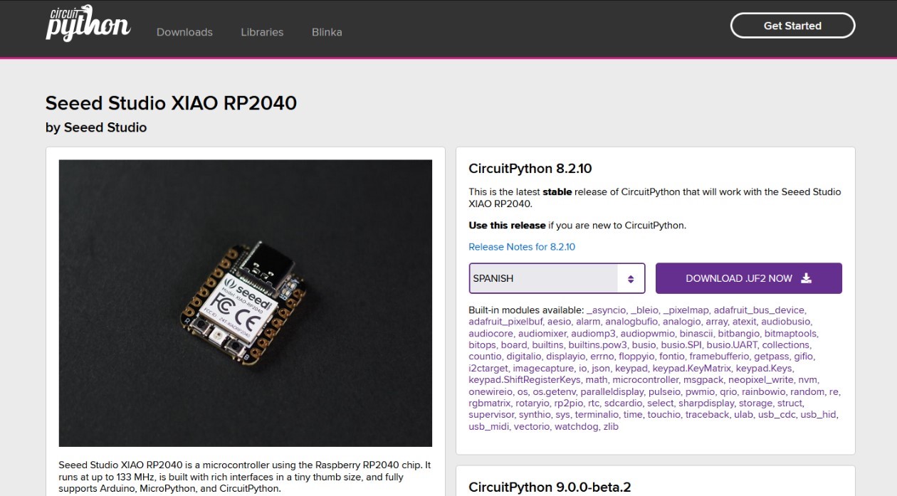
Loading the language
In the case of Arduino IDE what needs to be configured is the editor following the steps shown in Week 4, now for the case of circuitpython working with Mu you will need again to push the boot button to enter the default mode, then in your file manager, will be shown as an USB, in the official page for circuitpython find the .uf2 file for your microcontroller(there you can also find different libraries for aditional tools), download and copy it to.
I remember reading somewhere that there's an issue with circuitpython and the total usable memory is reduced to 1MB because of a missmatch with the real language space usage.
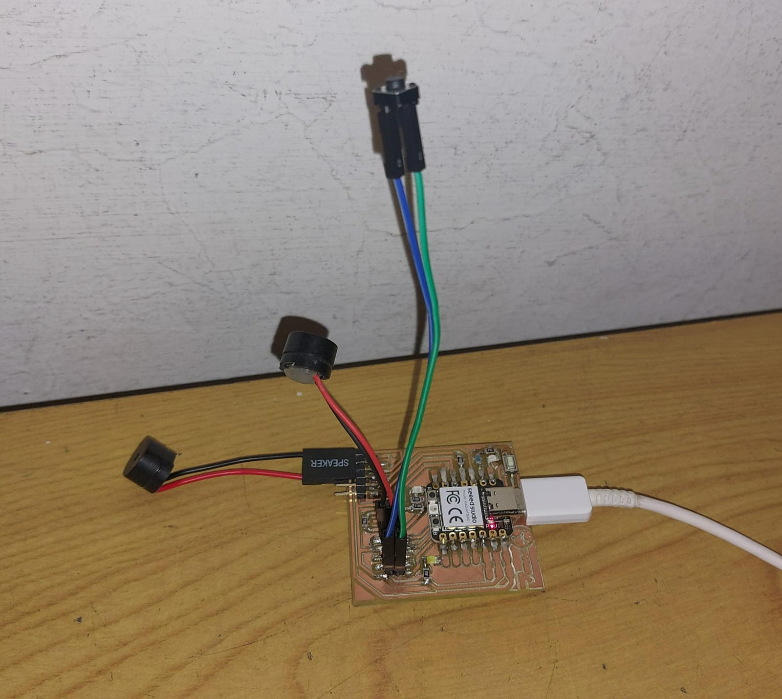
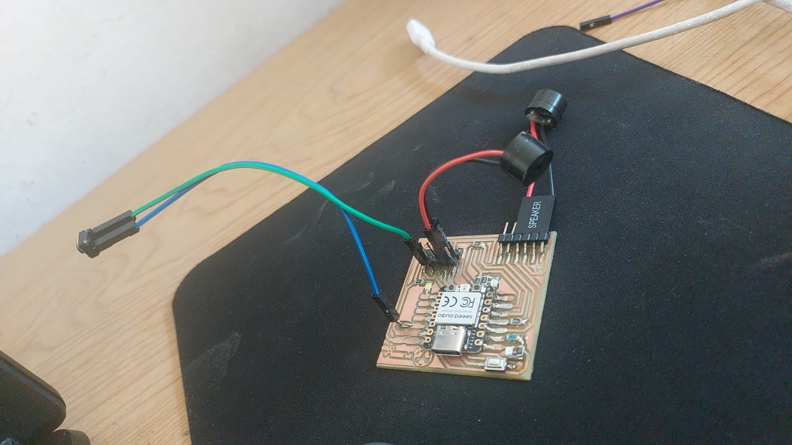
The components for this week.
Using the PCB with the Seeed studio rp2040 i have: 3 working diodes with the correct resistor, 1 NEOPIXEL integrated that should always work, 2 buttons( one is soldered on the PCB, for the other one used the pins and female cables), 2 PC buzzer that were part of my father waste before and my cat as emotional support.

-
I forget to document the diagram that shows where's the ground needed for each pair of pins and the rial that gets into the Seeed, also the buzzers have the convention (usually) where the black cable is the ground and the red is the one who receives the information.
With no further delay we can start programming.
Working with circuitpython
This week final code in circuitpython to download: code.py and the folder with the sounds sounds.zip.
I started the investigation with this language thanks to the circuitpython Essentials, In this page you can find what you need to build almost everything, then in the same learn adafruit page there's more complex task for circuitpython like this multi-tasking-with-circuitpython or debouncer-library-python-circuitpython-buttons-sensors.
For this week the first thing to do is learning to manipulate-interact-get to the components of the PCB, so with Mu editor opened i've created the next code:
# Import section
import board, time, digitalio, pwmio, neopixel
from audiocore import WaveFile
from audiopwmio import PWMAudioOut as AudioOut

# Audio buzzer section
audio1 = AudioOut(board.D2)
audio2 = AudioOut(board.D9)
path= "sounds/"
# Led section
led = digitalio.DigitalInOut(board.D6)
led.direction = digitalio.Direction.OUTPUT
led1 = digitalio.DigitalInOut(board.D7)
led1.direction = digitalio.Direction.OUTPUT
led2 = digitalio.DigitalInOut(board.D0)
led2.direction = digitalio.Direction.OUTPUT
# Buttons section
button = digitalio.DigitalInOut(board.D8)
button.direction = digitalio.Direction.INPUT
button.pull = digitalio.Pull.UP
button2 = digitalio.DigitalInOut(board.D1)
button2.direction = digitalio.Direction.INPUT
button2.pull = digitalio.Pull.UP
# Neopixel section
neopin = board.NEOPIXEL
num_pixels = 1
pixels = neopixel.NeoPixel(neopin,num_pixels, brightness=0.3, auto_write=False)


def color_chase(color, wait):
    for i in range(num_pixels):
        pixels[i] = color
        time.sleep(wait)
        pixels.show()


def rainbow_cycle(wait):
    for j in range(255):
        for i in range(num_pixels):
            rc_index = (i * 256 // num_pixels) + j
            pixels[i] = colorwheel(rc_index & 255)
        pixels.show()


RED = (255, 0, 0)
YELLOW = (255, 150, 0)
GREEN = (0, 255, 0)
CYAN = (0, 255, 255)
BLUE = (0, 0, 255)
PURPLE = (180, 0, 255)

# Functions section
def play_sound(filename, texit,butto):
    with open(path + filename, "rb") as wave_file:
        wave = WaveFile(wave_file)
        texit.play(wave)
        print(f"Playing {filename}")

        texit.pause()
        print("Waiting for button press to continue!")
        while butto.value:
            pass
        texit.resume()
        while texit.playing:
            if led.value == False:
                led.value = True
            else:
                led.value = False
            if led2.value == False:
                led2.value = True
            else:
                led2.value = False
            if led1.value == True:
                led1.value = False
            else:
                led1.value = True

        print("Done!")
# Loop section
x = True
while x:

    color_chase(RED, 0.1)  # Increase the number to slow down the color chase
    color_chase(YELLOW, 0.1)
    color_chase(GREEN, 0.1)
    color_chase(CYAN, 0.1)
    color_chase(BLUE, 0.1)
    play_sound("buop.wav", audio2,button)
    play_sound("wand.wav", audio1,button2)
This first code should show the entirity of the components working when pressing the 2 buttons, however there's one button doing nothing, and the program suddenly stop.
After an information odyssey and an electronics class, it turns out I dared to assume that I could connect a button to the ground, fortunately nothing serious happened when I landed the PCB and the ground. So I had the option of opening another door of my microcontroller or connecting another pin to the 3V path, I connected another pin.
For the other components: the buzzers obviously they're connected to the ground in the black wire, while the red is where the information will be sent, if it were a larger speaker would have another that would function as direct power.
To get the different sounds i found this website for short sounds, then to convert them to .wav or reduce the frequency to 22k i used the audacity software. The next code shows all the components and functions working as intended.
# Import section
import board, time, digitalio, pwmio, neopixel
from audiocore import WaveFile
from audiopwmio import PWMAudioOut as AudioOut
from rainbowio import colorwheel
# Audio buzzer section
audio1 = AudioOut(board.D2)
audio2 = AudioOut(board.D9)
path= "sounds/"
# Led section
led = digitalio.DigitalInOut(board.D6)
led.direction = digitalio.Direction.OUTPUT
led1 = digitalio.DigitalInOut(board.D7)
led1.direction = digitalio.Direction.OUTPUT
led2 = digitalio.DigitalInOut(board.D0)
led2.direction = digitalio.Direction.OUTPUT
# Buttons section
button = digitalio.DigitalInOut(board.D1)
button.direction = digitalio.Direction.INPUT
button.pull = digitalio.Pull.DOWN
button2 = digitalio.DigitalInOut(board.D8)
button2.direction = digitalio.Direction.INPUT
button2.pull = digitalio.Pull.DOWN
# Neopixel section
neopin = board.NEOPIXEL
num_pixels = 1
pixels = neopixel.NeoPixel(neopin,num_pixels, brightness=0.3, auto_write=False)

def color_chase(color, wait):
    for i in range(num_pixels):
        pixels[i] = color
        time.sleep(wait)
        pixels.show()


def rainbow_cycle(wait):
    for j in range(255):
        for i in range(num_pixels):
            rc_index = (i * 256 // num_pixels) + j
            pixels[i] = colorwheel(rc_index & 255)
        pixels.show()


#Define colors for color_chase
RED = (255, 0, 0)
YELLOW = (255, 150, 0)
GREEN = (0, 255, 0)
CYAN = (0, 255, 255)
BLUE = (0, 0, 255)
PURPLE = (180, 0, 255)
# Functions section
def play_sound(filename, sndexit,butto):
    with open(path + filename, "rb") as wave_file:
        wave = WaveFile(wave_file)
        sndexit.play(wave)
        print(f"Playing {filename}")
        sndexit.pause()
        print("Waiting for button press to continue!")
        while not butto.value:
            pass
        sndexit.resume()
        while sndexit.playing:
            pass
        if led.value == False:
                led.value = True
        else:
                led.value = False
        if led2.value == False:
                led2.value = True
        else:
                led2.value = False
        if led1.value == True:
                led1.value = False
        else:
                led1.value = True
        print("Done!")
# Loop section
x = True
while x:
    rainbow_cycle(1)
    play_sound("buop.wav", audio2,button)
    play_sound("wand.wav", audio1,button2)
Now we can use the components to simulate a car ignition:
# Import section
import board, time, digitalio, pwmio, neopixel
from audiocore import WaveFile
from audiopwmio import PWMAudioOut as AudioOut
from rainbowio import colorwheel
# Audio buzzer section
audio1 = AudioOut(board.D2)
audio2 = AudioOut(board.D9)
path= "sounds/"
# Led section
led3 = digitalio.DigitalInOut(board.D6)
led3.direction = digitalio.Direction.OUTPUT
led1 = digitalio.DigitalInOut(board.D7)
led1.direction = digitalio.Direction.OUTPUT
led2 = digitalio.DigitalInOut(board.D0)
led2.direction = digitalio.Direction.OUTPUT
leds = [ led3,led1,led2]
# Buttons section
button = digitalio.DigitalInOut(board.D1)
button.direction = digitalio.Direction.INPUT
button.pull = digitalio.Pull.DOWN
button2 = digitalio.DigitalInOut(board.D8)
button2.direction = digitalio.Direction.INPUT
button2.pull = digitalio.Pull.DOWN

# Neopixel section
neopin = board.NEOPIXEL
num_pixels = 1
pixels = neopixel.NeoPixel(neopin,num_pixels, brightness=0.3, auto_write=False)

def color_chase(color, wait):
    for i in range(num_pixels):
        pixels[i] = color
        time.sleep(wait)
        pixels.show()
    time.monotonic()

#Define colors for color_chase

Pure_red = (255, 0, 0)
R1 = (230, 26, 0)
R2 = (204, 51, 0)
R3 = (179, 77, 0)
R4 = (153, 102, 0)
R5 = (128, 128, 0)
R6 = (102, 153, 0)
R7 = (77, 179, 0)
R8 = (51, 204, 0)
R9 = (26, 230, 0)
Pure_green = (0, 255, 0)
G1 = (0, 230, 26)
colors = [Pure_red,R1,R2,R3,R4,R5,R6,R7,R8,R9,Pure_green,G1]
colors_count = 0
def getting_ready(filename, sndexit,butto):
    with open(path + filename, "rb") as wave_file:
        wave = WaveFile(wave_file)
        for i in leds:
            sndexit.play(wave)
            print("Setting the engine")
            sndexit.pause()
            print("Waiting for button press to continue!")
            while not butto.value:
                pass
            i.value = True
            sndexit.resume()
            while sndexit.playing:
                while colors and sndexit.playing:
                    color_chase(colors[0],0.2)
                    colors.pop(0)
        print("Engine Set")

def lets_get_out(filename, sndexit,butto):
    with open(path + filename, "rb") as wave_file:
        wave = WaveFile(wave_file)
        sndexit.play(wave)
        sndexit.pause()
        print("Waiting for button press to scape!")
        while not butto.value:
            pass
        sndexit.resume()
        while sndexit.playing:
            pass
#Loop Section
getting_ready("car.wav", audio1,button2)
lets_get_out("ready.wav", audio2,button)
Video of the result:
Arduino ide
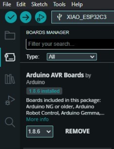
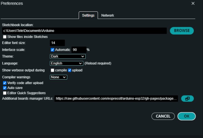
This week final code in arduino to download: buzzer.ino.Now that i have more experience with arduino there's some clearly advantages: Adding new boards via the board manager or aditional url manager in the file-preferences tab
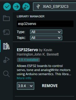
And the ease of use of libraries with the library manager or the option to add via zip from github or other sources
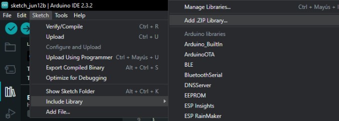
Translating the previous code to the C++ arduino language, remember to replace the "" with >, the next code reassemble the circuitpython one, but using simple tones as it isn't as easy to manage flash memmory in arduino:
First we import the libraries with the #include and the name then we use the #define to give a name to the pin and the location i like to use the letternumber direction to avoid issues with many boards, with the execption of the built in things where the manufacturer especify it's pin number.
#include "Adafruit_NeoPixel.h"

// Pin definitions
#define AUDIO_PIN1 D2
#define AUDIO_PIN2 D9
#define LED_PIN3 D6
#define LED_PIN1 D7
#define LED_PIN2 D0
#define BUTTON_PIN1 D1
#define BUTTON_PIN2 D10


// Number of NeoPixels
#define NEOPIXEL_PIN 12
int Power = 11;
#define NUMPIXELS 1

// NeoPixel object
Adafruit_NeoPixel pixels(NUMPIXELS, NEOPIXEL_PIN, NEO_GRB + NEO_KHZ800);
In arduino, c, exist a more eficcient way to save resources calling static, unsigned, size of the element, that's why you found many types of int, char, bool, byte, etc..
// Led and button setup
int leds[] = {LED_PIN3, LED_PIN1, LED_PIN2};

// Color definitions
uint32_t colors[] = {
    pixels.Color(255, 0, 0),
    pixels.Color(230, 26, 0),
	pixels.Color(204, 51, 0),
	pixels.Color(179, 77, 0),
    pixels.Color(153, 102, 0),
	pixels.Color(128, 128, 0),
	pixels.Color(102, 153, 0),
    pixels.Color(77, 179, 0),
	pixels.Color(51, 204, 0),
	pixels.Color(26, 230, 0),
    pixels.Color(0, 255, 0),
    pixels.Color(0, 230, 26)
};
int colors_count = 0;
int total_colors = sizeof(colors) / sizeof(colors[0]);
Instead of the "def" function in python in arduino we have void functions with two special ones, the setup and the loop, it doesn't matter where you place them as the instructions will ever be first the program will run the setup function one time and then run whatever is inside the loop as a loop, in the setup function you usually set the pinMode of the pins, set some digital writes in the OUTPUTS and begin some libraries, also all the parts of the Serial family are used to communicate with the pc by USB.
void setup() {
    // Initialize pins
    pinMode(LED_PIN3, OUTPUT);
    pinMode(LED_PIN1, OUTPUT);
    pinMode(LED_PIN2, OUTPUT);
    pinMode(BUTTON_PIN1, INPUT);
    pinMode(BUTTON_PIN2, INPUT);
    pinMode(Power,OUTPUT);
    digitalWrite(Power, HIGH);

    // Initialize NeoPixel
    pixels.begin();
    pixels.setBrightness(75);
    Serial.begin(9600);

}
The fist function is used to change the color of the neopixels in your project.
void color_chase(uint32_t color, int wait) {
    for (int i = 0; i < NUMPIXELS; i++) {
        pixels.setPixelColor(i, color);
        pixels.show();
        delay(wait);
    }
}
The first function to prepare the engine as in the previous code with a delay for the loop function to give time for the tone to end, then we wait for the button to be pressed checking every 10 milliseconds, turn one led, play the tone and change the neopixel color until the three leds are on.
void getting_ready(const int toneFrequency, int buttonPin) {
    delay(1000);
    Serial.println("Waiting for button press to continue!");

    while (digitalRead(buttonPin) == HIGH) {
        delay(10);
    }

    for (int i = 0; i < 3; i++) {
        digitalWrite(leds[i], HIGH);
        tone(AUDIO_PIN1, toneFrequency);  // Start playing tone
        for (int j = 0; j < total_colors; j++) {
            color_chase(colors[j], 200);
        }
        noTone(AUDIO_PIN1);  // Stop playing tone
    }

    Serial.println("Engine Set");
}
Something similar but intended to play with a different tone to reassemble the sounds in python.
void lets_get_out(const int toneFrequency, int buttonPin) {
    Serial.println("Waiting for button press to escape!");

    while (digitalRead(buttonPin) == HIGH) {
        delay(10);
    }

    tone(AUDIO_PIN2, toneFrequency);  // Start playing tone
    delay(2000);                      // Let the tone play for 2 seconds
    noTone(AUDIO_PIN2);               // Stop playing tone
}
At last run the code infinitely, if you want to run it once you can place the functions in setup.
void loop() {
    getting_ready(800, BUTTON_PIN2);  // Tone frequency 800 Hz
    lets_get_out(500, BUTTON_PIN1);    // Tone frequency 500 Hz
}
Final reflection
At first I didn't think about how comfortable it was to work with circuitpython to use the flash as non-volatile storage, since in most pcbs it's normal to use eeprom or a sd memory to store sounds or text files. I think that is one of the strengths of circuit python, in addition to that it is a limiting or advantage as the libraries that already come installed in the .uf2 are practically all you will find, while in arduino there is a much broader documentation for easily programming and installing the boards and libraries created by the community.