3. Computer controlled cutting
The first machine that we will learn to use is the laser cutting and then the vinil, working in group we will learn the structure of our laser cuter machine, some concepts of the laser cutting and types of joints, while individually i will design and lasercut a parametric construction kit and do a vinyl cut.
Learning to use the lasercutter
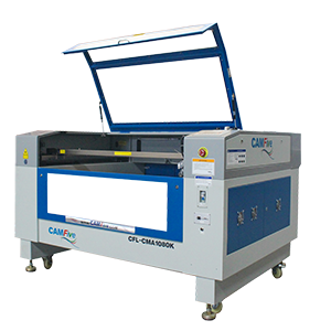
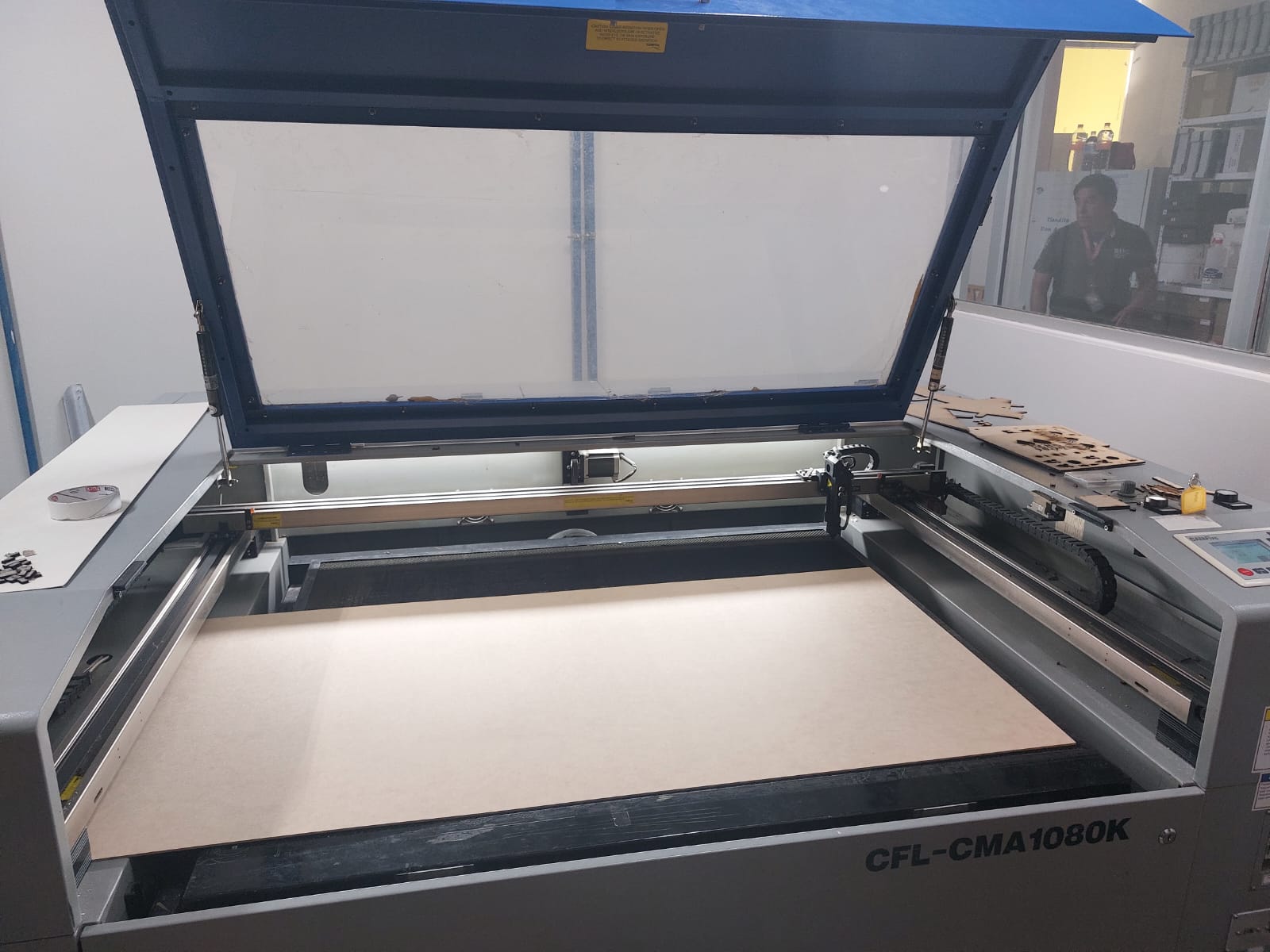
Brand-name of the laser cutter: CAM-five
Link to the official page.
This weeks group assignment consists in the theoretical part of laser cutting, the machines we have use CO2 tube technology, this means the laser will have some parameters to customize in order to make a clean cut.
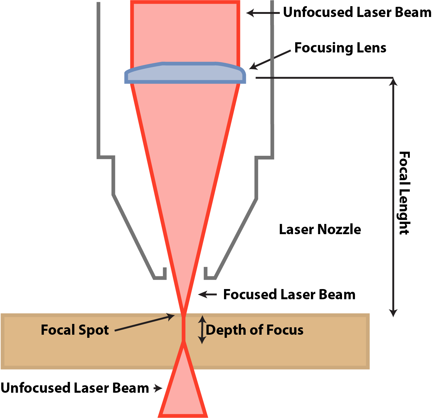
These machines utilize a specific focal point where the laser light converges with maximum intensity, allowing for optimal energy concentration in a defined area. Thanks to this precise focal point, laser cutters can effectively cut materials with a thickness of up to 8 mm in a single pass.
The work area of the machine is about 1.20 x 0.60 meters, it can cut and engrave:Acrylic, Cardboard, Cork, Cotton and mixed fiber fabrics, Felt, Foaming, MDF (pressed cardboard), Natural leather (leather), Paper, Plastic, Plywood (pressed wood), Rubber (rubber or latex), Synthetic fabric lycra and thin, Synthetic leather (leather), Thick synthetic fiber fabrics, Wood. Just engrave: Glass and crystals, Ceramic, Marble, onyx and other stones, Tile and Metal (apply special resin, laquer, etc). Avoid other materials!!!!
Speed and Power of the laser
-
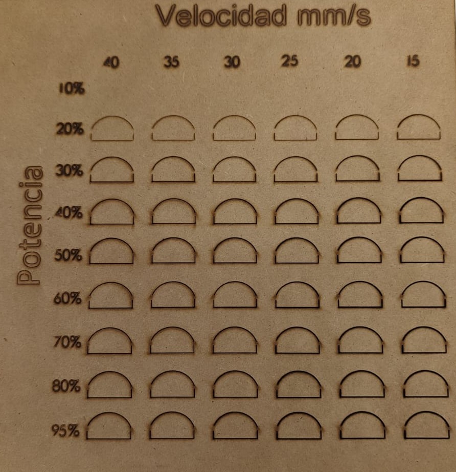
The power of the laser and the speed at which it moves are parameters that we must configure to achieve clean cuts, the higher the power, the more likely it is to cut, but it will likely dirty the material. Therefore, a combination of both is necessary. In the case of a 3mm MDF, with the laser well calibrated in the Z-axis, can be cut with a power setting of 60%-50% at a speed of 20 to 30, depending on the quality of the material. That's why it is recommended to conduct tests before sending the entire document for cutting.
Obviously if the more power you use the bigger the energy it consumes and the amount of kerf you get.
Kerf
-
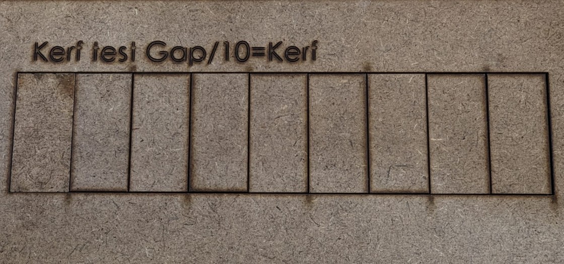
The kerf in a laser cutter refers to the width of the material that is removed during the cutting process. It is influenced by various factors, and it's dependant to the type of material being cut. Achieving an optimal kerf is crucial for precise and clean cuts. Controlling the kerf allows for greater accuracy in creating intricate designs and ensures minimal material wastage. In the case of 3mm mdf the kerf we get is about 0.123mm and for Acrylic .252 mm kerf.
Joints
-
The choice of joints plays a pivotal role in determining the structural integrity and aesthetics of the final product. The first type is the Butt Joint, where two edges of MDF meet at a right angle. Next is the Dowel Joint, involving the insertion of dowels into corresponding holes in the adjoining pieces. The third type is the Miter Joint, where the edges are beveled to create a clean, continuous surface when joined at an angle. Additionally, the Dado Joint involves creating a groove in one piece of MDF that accommodates the edge of another . Lastly, the Rabbit Joint features a groove on one panel into which the edge of the other panel fits.
lasercutter Instructions
Assisted Use
-
With a instructor help I learnt the steps required to use the lasercutter, in this case because im working with MDF the first step is to turn on the air extractor, then the laser cutter, twist the emergency button, turn on the laser and put it to the minimum power to place the material, then with the laser buttons set the origin in x, y, z, go to the computer, load your files and click the cut option.
Using the CAD software of your preference you will need to transform the files to .dxf, in SolidWorks just use the save function and change the extension, using the import face property you won't need to eliminate extra lines.
When you are setting the origin in this case the laser focal point is above 5 mm, we use an thiny USB or 3 one MXN pesos coins, then in the computer software we set the laser power around 50% and 60% with a velocity off 25 mm/s, and select up to 15 trails to follow for cutting or engraving each with different settings.
To make tests you can always use recycled material just remember to reloacte the test design in the software or directly in the axes, also the software allows you to make a path of the total area your design covers.
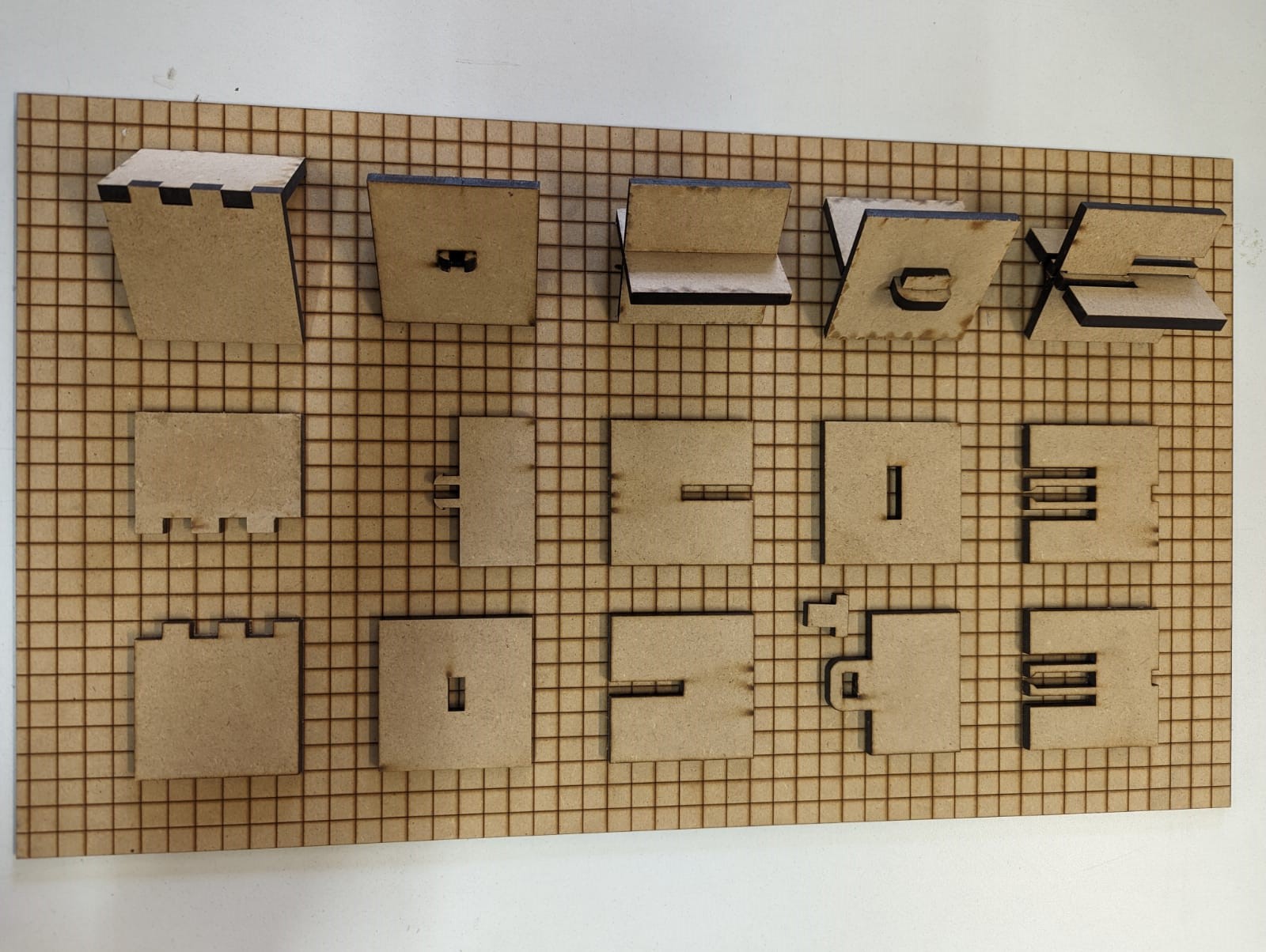
Test files:
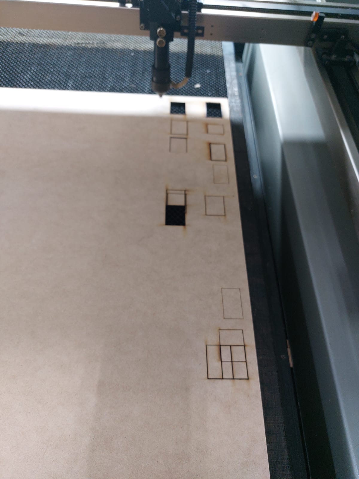
I created this 4 parts to test design and limits when working with joints and curves Part 1 , Part 2 , Part 3 Part 4, The image above is an example of those parts.
Parametric design
We say that something is parametic designed when we include ecuacions and not-fixed values to a CAD file, this modeling technic results especially helpfull when using different materials and production methods, allowing quick changes to fix design errors.
-
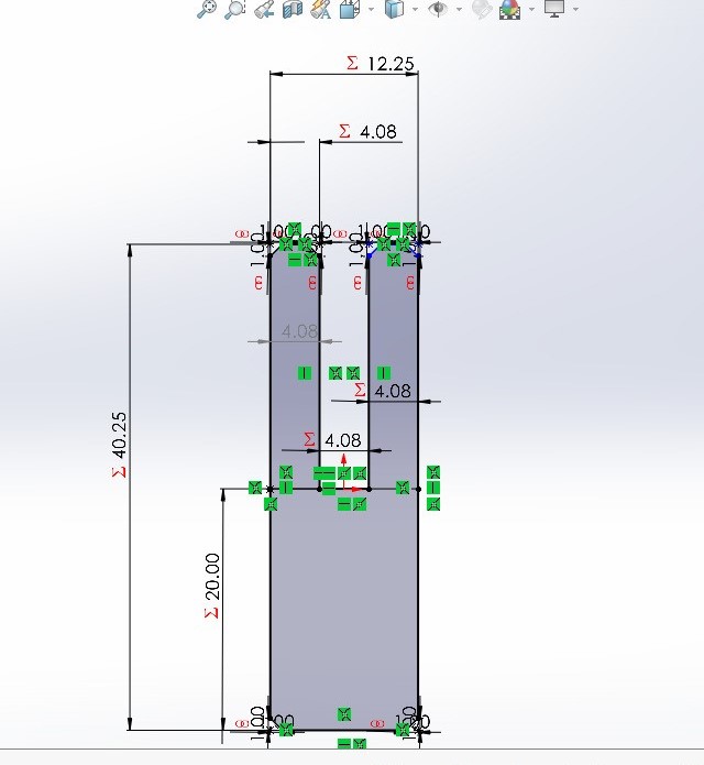
To learn the basics of parametric design i created the following part, when creating a parametric part you have to make an ecuation for every distance you set, then you can make operations with the variables you already set, also in solidworks you can use the visual basic structure for the if condition, this is helpfull when you are working with matrix designated for either cutting or extrusion.
In solidworks you can create a txt of ecuations to import and export across different parts, In the set of variables, we are counting with the kerf that allows us to modify it and the measures it's involved, the material, the general size of the set and the number of holes.
For the # of circle cuts you'll first make all the extructions needed; then using: circular, square, line follow matrix of a cut you can now use ecuations.
The part that will work as a screw, shares all the previous ecuacions in order to fit and transform to the size of the circle holes.
The half circle ecuations round.txt and the line ecuations line.txt the main difference of the files exists in the # of holes, because of the nature of the figure it needed different calibration.
-
For the ecuations to work i used the space between holes and the # of holes with to security checks to avoid failures:
- "space_hol" = ( "width" / 2 + "kerf" ) + 5
- "num_hol" = int ( "distance" / ( "width" / 2 + "kerf" ) )
- "num_hols" = IIF ( "space_hol" * "num_hol" >= ( "distance" + "space_hol" / 2 ) , "num_hol" - 1 , "num_hol" )
- "num_hol_fin" = IIF ( "num_hols" * "space_hol" >= ( "distance" + "space_hol" / 3 - 2 ) , "num_hols" - 1 , "num_hols" )
The set of ecuacions and the way they work with the other variables helps keeping proportional spaces if the size is either to small or gigantic.
-
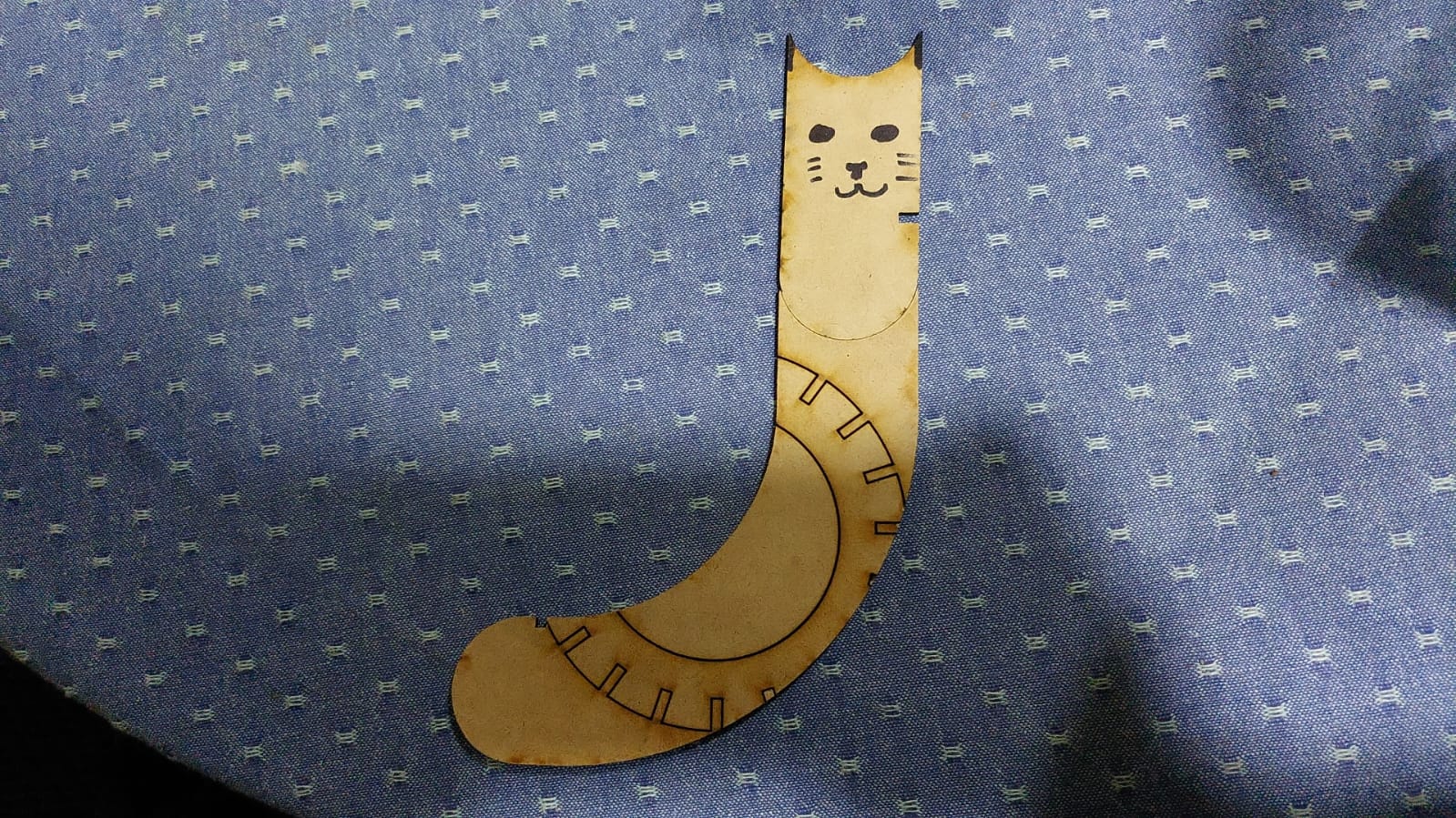
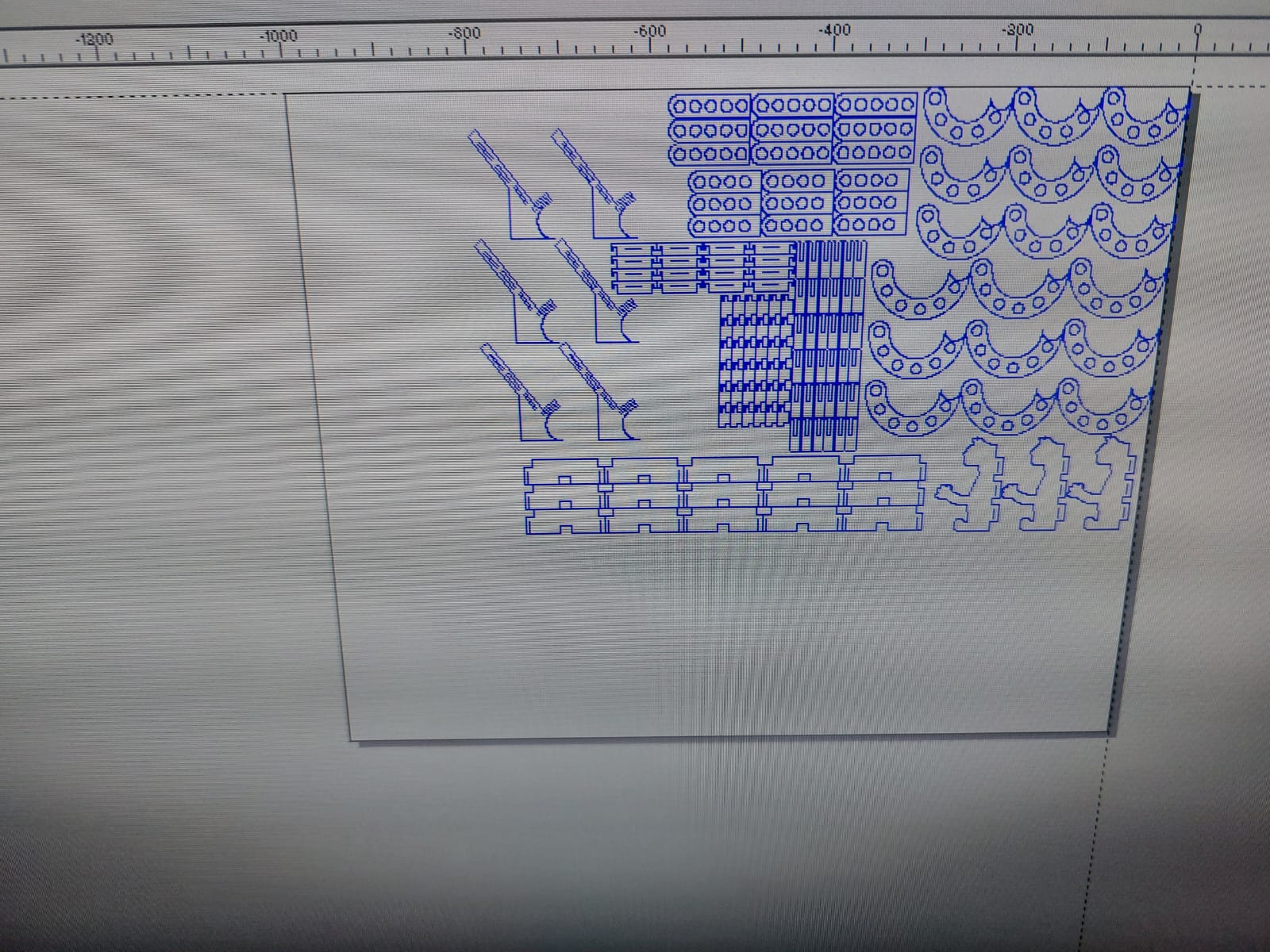
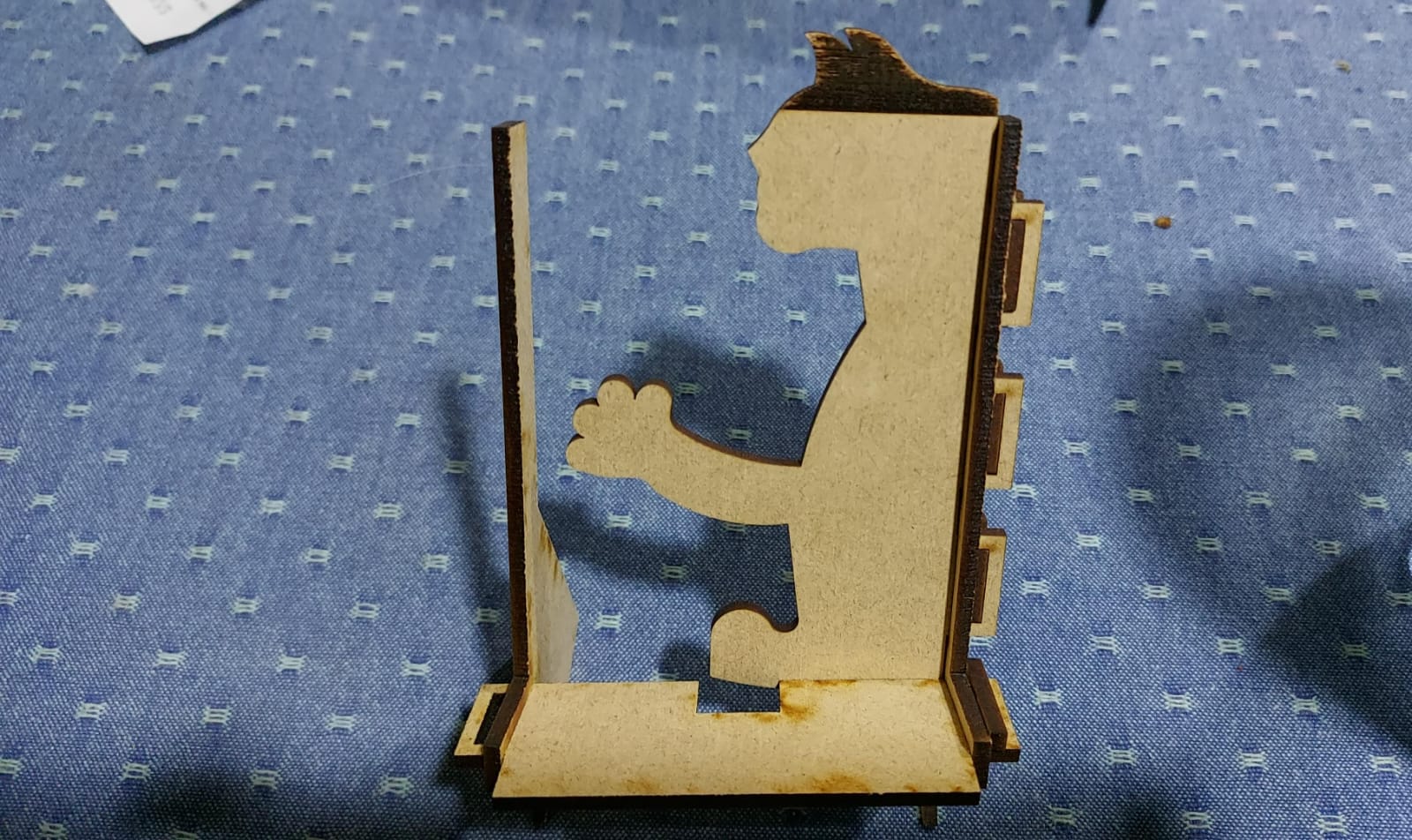
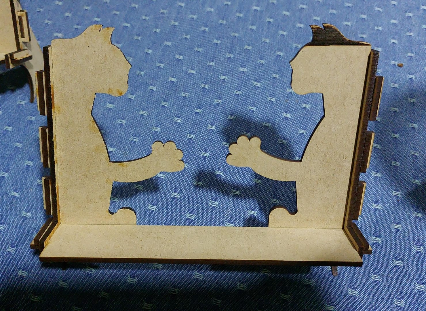
For the last construction set i wanted to make a support-er multipurpose, with a bad idea in mind i wanted to make a greeding cat into the design, that was a terrible idea for this assigment, because of the complex shape it was imposible to make it parametric, to solve the issue there's a special tool called scale, it's a solution to fix the size.
The parametric side of the set is saw in the other parts, especially in the size of the press fit joints, to match with material width.
I made different parts to enlarge, twist, make wider, make taller and customize the supoports.
-
Parts of the first set:
- Half-parametric-circle
- Straight line
- Connector
Parts of the support set:
- Stand up BASE
- Sleep BASE
- GATO
- Side piece to unite all
- Side piece to unite some
- Stay there piece
- To connect in X
- To connect in Y
SolidWorks documents:
-
Parts of the first set:
- Half-parametric-circle 5 holes
- Half-parametric-circle 6 holes
- Straight line 5 holes
- Straight line 4 holes
- Connector
Parts of the support set:
- Stand up BASE
- Sleep BASE
- GATO
- Side piece to unite all
- Side piece to unite some
- Stay there piece
- To connect in X
- To connect in X
.DXF documents:
Cutting the pieces
-
I placed my complety new MDF table and set the origins in the superior right corner.
-
I started making test to get the best power/speed ratio to cut, but after 20 or more tries i found it really difficult to cut even with a super slow speed and 90% power it needed two runs to cut, when normally a half power, double speed would be enough.
-
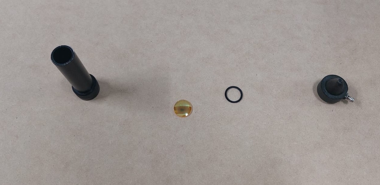
At that point it wasn't a calibration problem, there was something wrong in the machine, so i called an instructor for some assistance to solve the issue.
At first we found the air compressor tube from the laser was damaged, we removed the broken part and the air returned to the normal flow, but the problems remained, now the next probably damaged part was the magnifying glass of the laser, because of the lack of air flow the lens could be burnt, luckily it just needed a little cleaning with isopropylic alcohol.
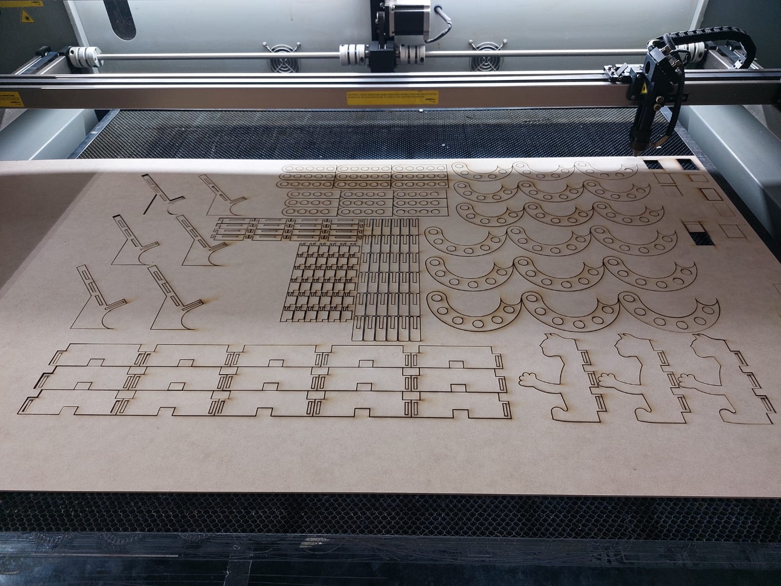
After that it worked as intended, so i imported the files into the software, created a matrix put of each one of them and defined the usual potency of the laser to 45%-55% of the laser's power and a velocity of 25 mm/s.
After all those problems i finally sent cutting the remaining pieces.
src="../assets/images/week3/vid2.mp4" width="50%" autoplay loop muted>Payoff
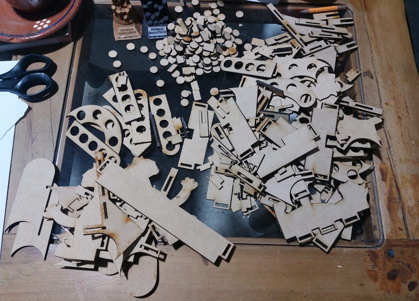
Now that i can finally get my laser cutted pieces, after all of thaht hard works the moment has arrived, it's time to take all the pieces and throw the remaining mdf in the recycling box next to the machine. When i arrived at my house, after i cleaned the two construction sets i put the circles in bag as possible poker chips.
Then made some quick models with both sets.
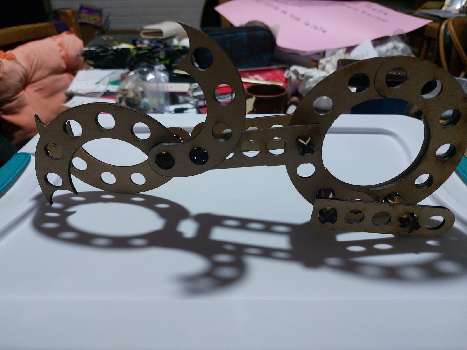
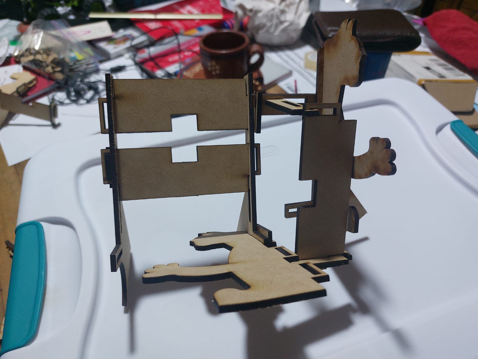
And get the stands i wanted.
Vinyl Cutting
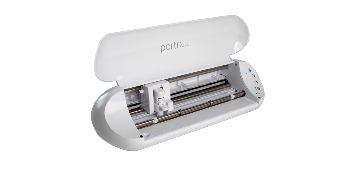
Using this little Silhouette portrait 3 you can design and cut different vinyls easily, the software Silhouette Studio allows you to export your png, jpg and basic image fyles, it's a little strange that this doesn't support .svg files.
It allows you to cut the dimensions of 20cm * 30cm in one movement, with the help of an extra tool you could get creative for bigger designs up to 18.288m, it's designed to cut a variety of materials including vinyl, paper, specialty patterned papers, cardstock, vellum, iron-on heat transfer material, fabric (when using our Interfacing products) and sticker paper among other materials.
How to easily use this vinyl cutter
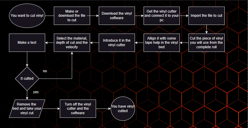
-
My experience in vinyl-cutting
-
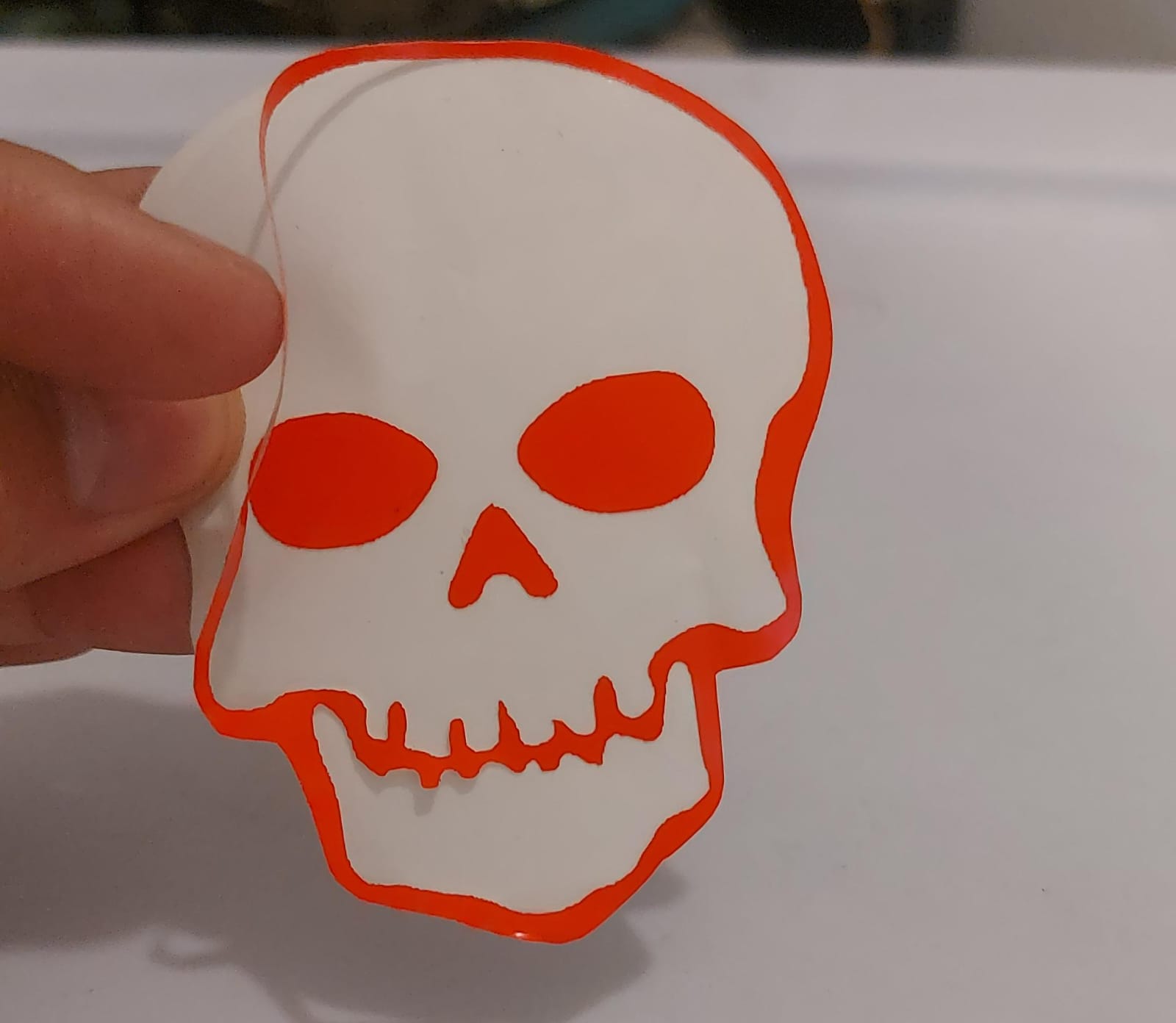
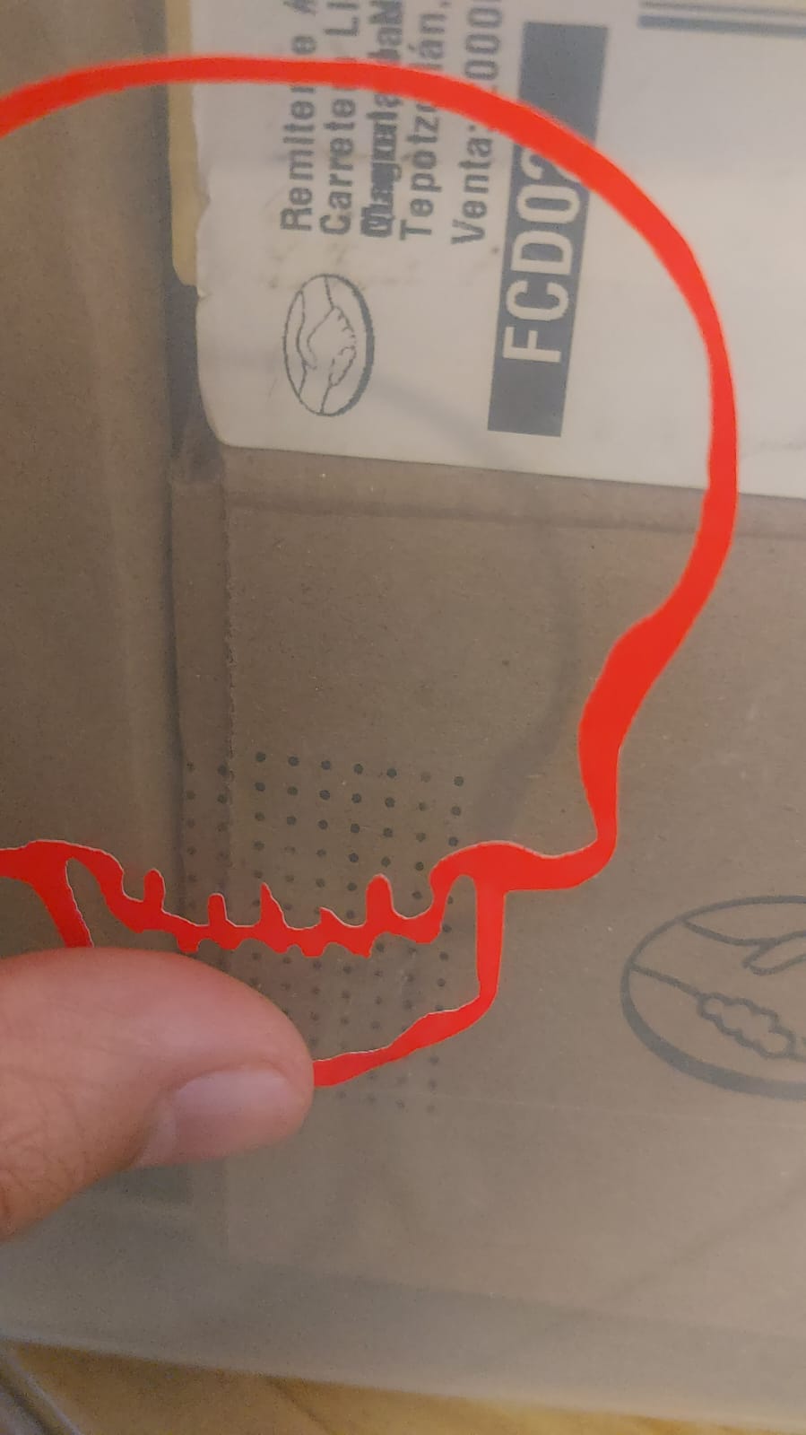
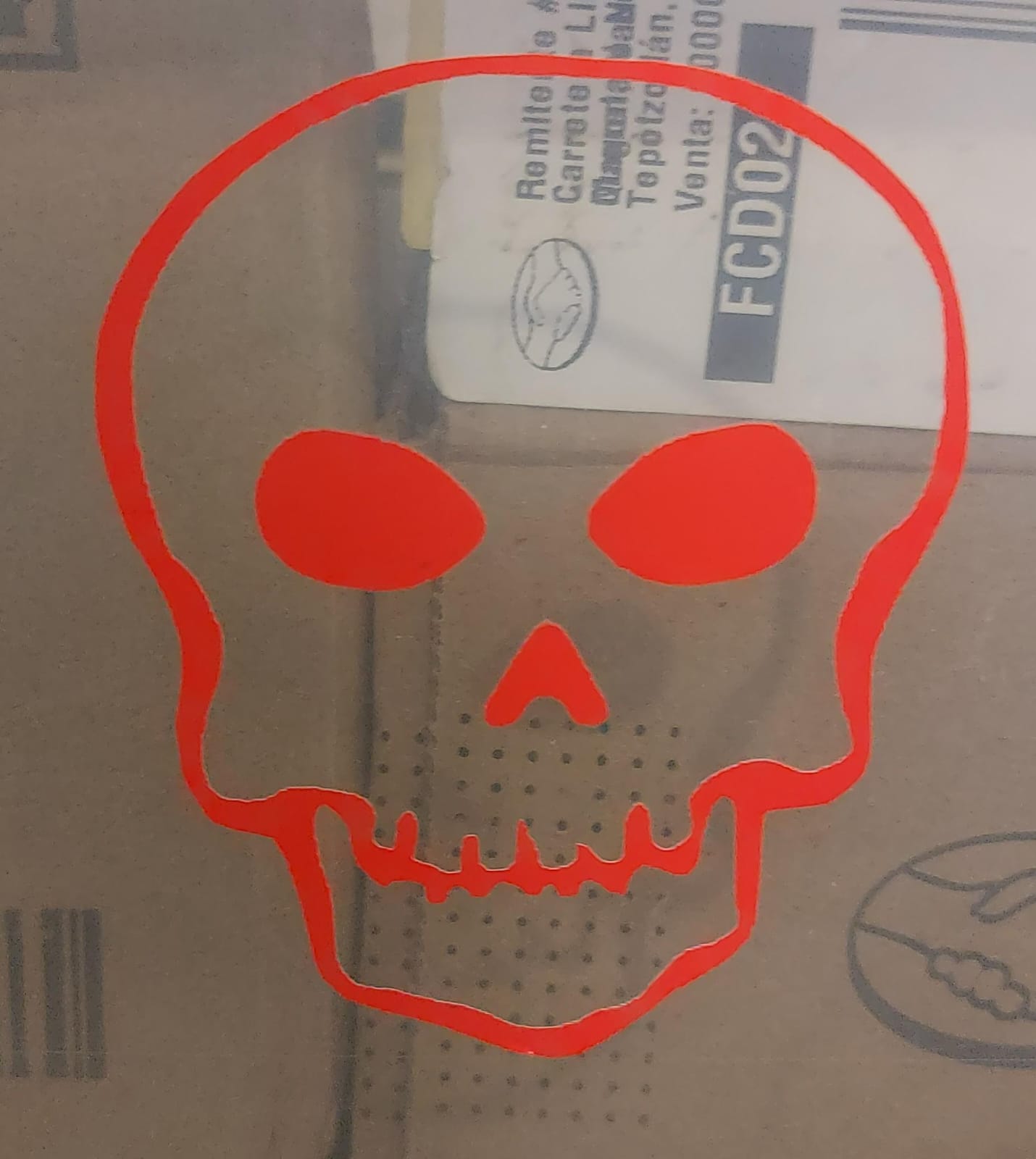
The first .png that i downloaded, when i imported it to the software discovered that it was a fake .png, even that i passed the image between many files converters it didn't pass the minimum quality for the software to make a good cut, so i changed the the image to a more generic one (Skull PNG), now that the program correctly traced the image (you can see the red border lines), i decided to use a bright red vinyl, cut a square and match the dimensions of the square and the image in the Silhouette software, then used some tape to fix it's position in the bed.
-
Click in the 'enviar' that it's the send option to the vinyl cutter with the parameters of: the selected material vinyl, 1 trace and blade depth of 1, it achieved a simple outline of the vinyl, that made me think of changing the depth to 3 and with that changed, i confirmed that in order for this vinyl-cutter model, to make a clean cut in Common vinyl, at least a blade depth value of 3 would be needed.
-
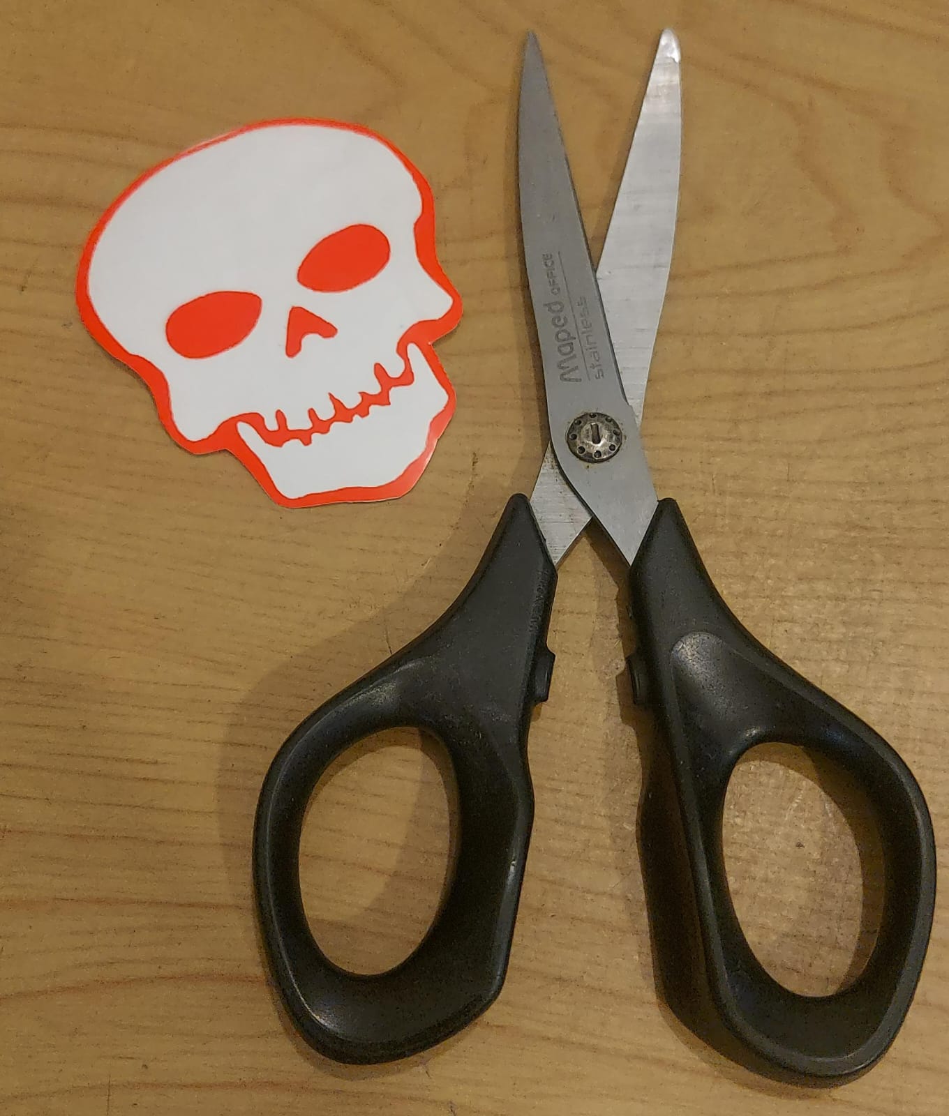
The vinyl I chose was a label so I removed the inside and stuck it directly, applying a little pressure, as you can see on the laptop, unfortunately i did not take a picture of the full vinyl with the skull cutted, but I took advantage of scissors to trim the edge and have an alternate design.
As you can see, it is very easy to peel off and adheres very strongly to the surface you put it on using minimal force from your finger. In addition, the advantage of using vinyl is that it does not bend or wrinkle easily compared to a normal label.
i used the Oracal 6510 Flúor Cast fluorescent red vinyl That thanks to its excellent quality it did not give me any problems.
I was a little confused, I don't know why I thought that the vinyl had a lower transfer sheet to which it was glued and this didn't stay with the glue, but in this case the vinyl works the same as a normal label where there are two layers for easy handling, now i know that the transfer paper is commonly used to add your vinyl cuts to shirts and other places applying heat, i will test that later on.

Final reflection
When cutting with laser, to get a clean cut, you end up making at least four test cuts, since you want your final result not to be so blemished. On the design side, I was surprised by the level of equations that SolidWorks can support. Finally, you always have to remember two things: kerf + margins between pieces. If you forget about the kerf, the assemblies will end up with gaps, and if you don't take margins into account, it's very likely that the pieces will collide with each other.