Input, that means fancy gizmos?
There is no I in team
Before we get into any individual activities, I'd like to share the group site for this particular assignment.
Sensors, what is up with them?
The sensors are input devices that provides an output with relation of a physical quantity. Device that converts signals from one energy domain to electrical. There are a lot of different sensors depending on the application you want. Temperature, proximity, acceleration, infrared, pressure, light, distance, humidity, you name it.
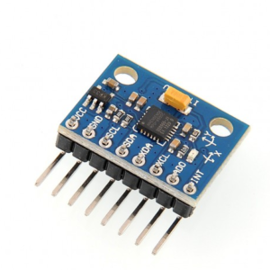
In my case, I'll be using an MPU 6050 accelerometer & gyroscope sensor for what would be described as a primitive version of a tiny mo-cap (motion capture) arrangement.

This device, hooked up on a PCB board enables me to know the angles in which the sensor is currently located, the position will be shown on the Arduino IDE software terminal.
Designing & Assembly
So the design is the one used in the final project, time to load in your favorite electronic design tool! I preffer EasyEDA but as I said, you can use whichever software you like, here's the design and a 3D projection.
Now, a bit of a sidebar here, it can be easy to notice that there might be some through-holes in the desing, fear not, they are not going to be used as holes, they are marked as such but in reality, these spots are designated male pin header sections to connect other devices and to have easy access to the MCU.
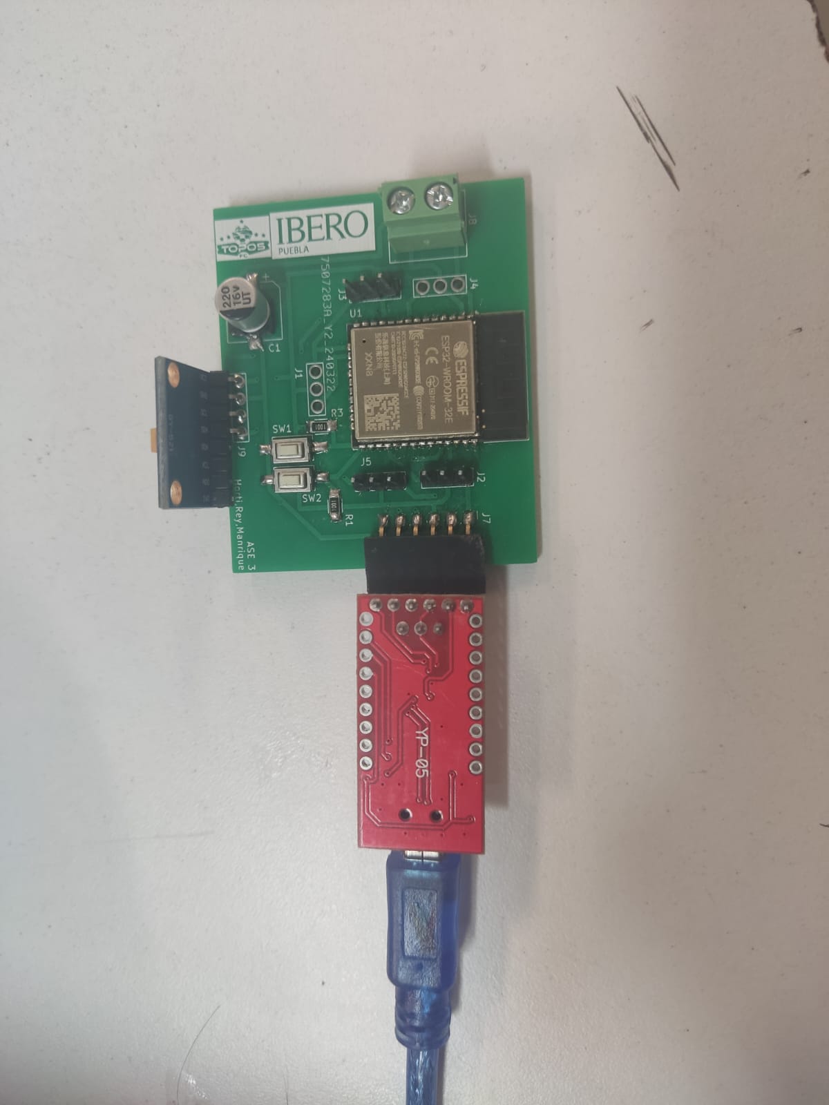
Let me explain the other components that this PCB board has:
- MCU: ESP32-WROOM-32E wifi, the microprocessor that computes and transmits all sorts of instructions and data.
- Push Buttons, two buttons that are used for RESETING and BOOTING the board itself.
- MPU 6050, the sensor we already talked about.
- SMD 1206 Resistors, these are used for the proper power management throughout the board's components.
- Dual wiring terminal, used for an alternative source of power, which is fed via batteries.
- 16V Aluminum Electrolytic Capacitor, used to operate DC voltage.
- Male & Female Pin Headers, used for PCB configuration and connecting other devices for further use.
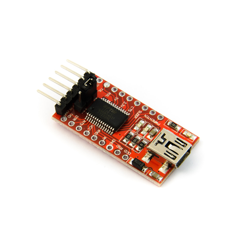
- FTDI Programmer for ESP32, this is a programmer device that is required for the user to load code into the MCU.
Also, in a bit of sad news, I had to get this particular board made out of FR-4 as the complexity of the circuit board and the usual unavailability of the milling machine due to malfunction and repairs made keeping a decent deadline difficult.
Nevertheless, the assembly was indeed done by yours truly, as well as the programming.

Programming & Testing
So, in order to program the ESP32 we need an FTDI programmer, it's a device used to configure ESP32 MCUs and it can also be a source of voltage (if your board's voltage needs aren't really high). This is plugged both into the computer and your PCB, so there has to be some consideration in designing a proper i/o port so that it can be used.

We open up the Arduino IDE programming platform and compile the code below to perform the desired function.
Once we compiled the code and checked for any errors that may have slipped in thourhg the initial programming phases we connect the board to the FTDI and then load the code into the PCB by pressing the Upload button (which is an arrow pointing to the right) located at the top-left corner of the panel while also pressing both the BOOT and RESET buttons on the board so that the MCU is able to get the code loaded.
Here is one of the testing runs I did.
In the terminal we can observe that the MPU6050 is capturing the X and Y angles in spanish as the PCB is moving. So, that's it for this assigment, I hope you have a great day!
