Electronics production
PCB
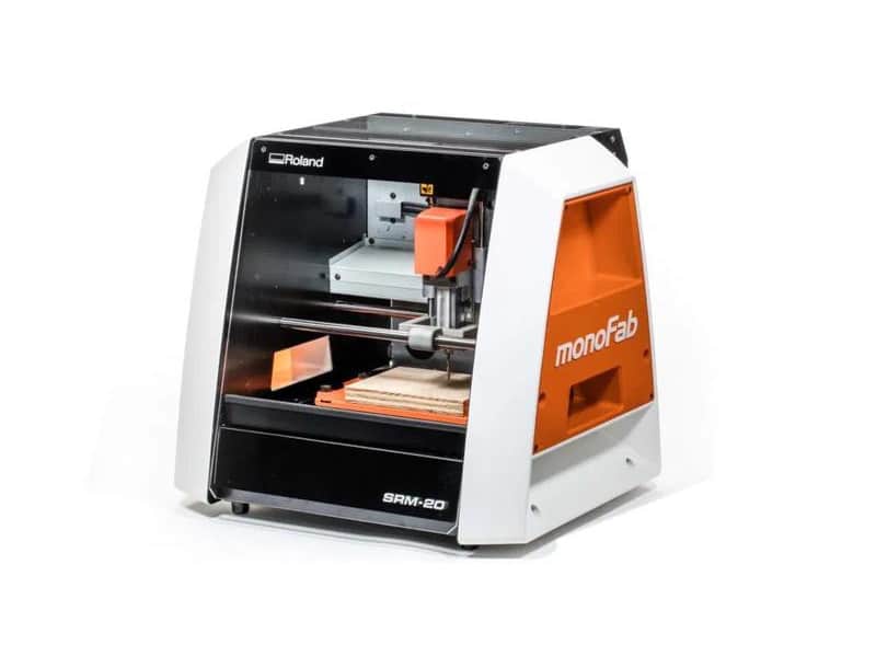
This week's assignment involved creating a homemade PCB (Printed Circuit Board). At Fablab Puebla, we have three models of Mini Mills: the "Roland SRM-20," "MDX-20," and "Lunyee." However, we opted to use the "Roland SRM-20" due to its superior precision. Precision is crucial for PCB milling because it requires repeatability and accuracy, especially for fine details. If you want more details of the other Mini Mills go to the group assignment and click the link.
Roland SRM-20
The Roland SRM-20 operates by employing a high-speed rotary cutter to remove excess copper from a copper-clad
substrate. This process precisely carves pathways, forming the circuit on the board. Here are the specifications
of the Roland SRM-20:
- Cutable Material: Modeling Wax, Chemical Wood, Foam, Acrylic, Polyacetal, Acrylonitrile Butadiene Styrene (ABS), Printed Circuit Boards.
- Operational Travels in X, Y, and Z: 203.2 mm (X) × 152.4 mm (Y) × 60.5 mm (Z).
- Loadable Workpiece Weight: 2 kg.
- Operation Speed: From 6 mm/min to 1,800 mm/min.
- Software Resolution: 0.01 mm/step (RML-1), 0.001 mm/step (NC Code).
- Mechanical Resolution: 0.000998594 mm/step.
- Spindle Rotation Speed: Adjustable from 3,000 RPM to 7,000 RPM.
- Interface: USB.
- Operational Noise: During operation: 65 dB(A).
- External Dimensions: 451 mm (width) × 426.6 mm (depth) × 426.2 mm (height) (17.76 in [width] × 16.80 in [depth] × 16.78 in [height]).
- Weight: 19.6 kg.
Group assignment
This week's group assignment was to thoroughly understand the machine we'll use for PCB fabrication. This
involved familiarizing ourselves with all aspects of the process, including document feed, speeds, depth of
cut, and other relevant parameters. Additionally, we explored how the PCB design can be sent to an external
facility for manufacturing.
You can find all the crucial information about the Mini Mills on this page. It includes details on how the
different models operate, the compatible materials list, safety guidelines, tooling information, and much
more. Access all of this important information through clicking here.
Making my own pcb
Mods
To begin with, we need to navigate to the mods page to generate the code that the machine will use to fabricate the PCB. You can access this page through the group assignment page or by clicking here. Once on the mods page, right-click on the screen to bring up a menu. Then, select "Programs" and choose "Open Program." Scroll down until you locate the SRM-20 section, and click on "Mill 2 PCB." This action will prompt a series of containers to appear, allowing you to proceed with the PCB fabrication process.
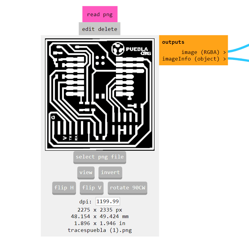
From this point, you'll want to navigate to the "Read PNG" menu and press the "Select PNG file" button.
I personally chose to use a PNG image named "Tracespuebla" that was provided to us for the cutting process.
Note: You can download these images at the bottom of the page for your convenience.
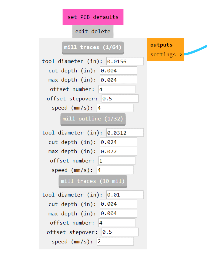
Under the "Read PNG" menu, there's another menu below called "Set PCB defaults." From here, you'll want to press the "Mill traces (1/64)" button. This selection is specifically fitted to my requirements, but you should choose an option based on your own needs and preferences.
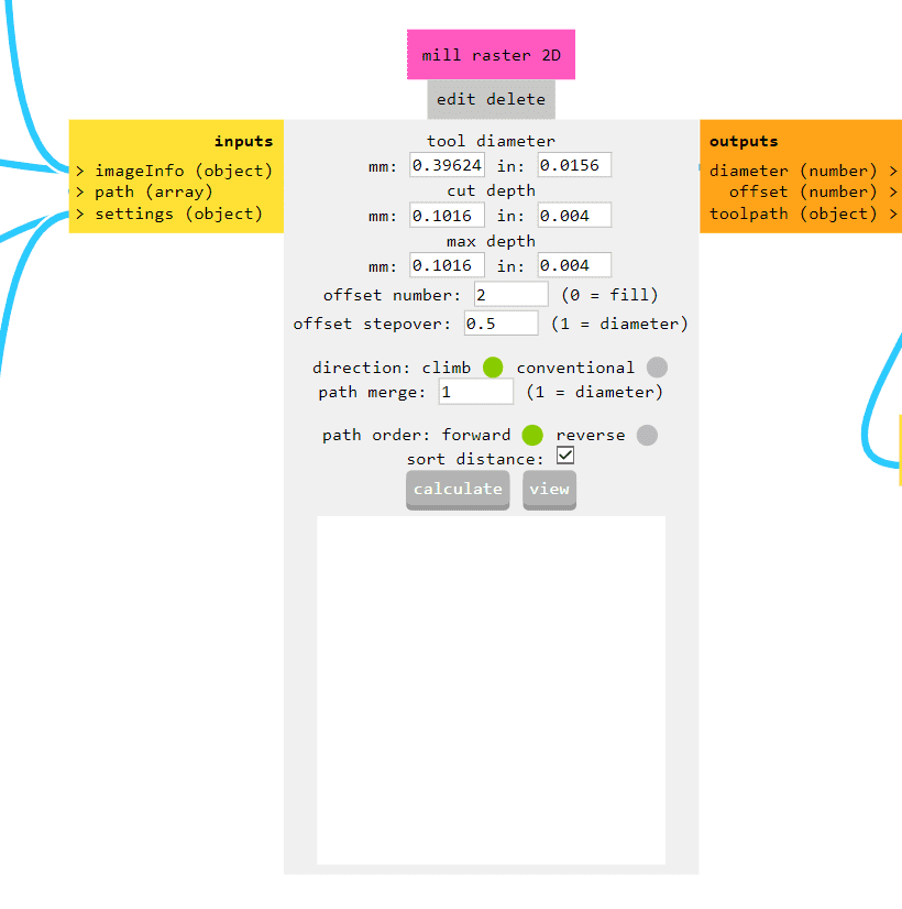
In the middle of the page, you'll find a menu called "Mill raster 2D," which is responsible for generating the document that the SMR-20 will follow. The only modification you need to make here is to adjust the "Offset number." By default, it's set to 4, but in my case, I'm changing it to 2. This option determines how the machine will start the process differently. The file will be created when you press the "Calculate" button. However, hold off on pressing it just yet, as there are more adjustments we need to make before generating the file.
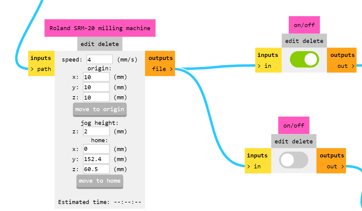
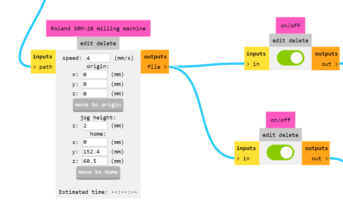
If you move to the right from the previous step, you'll encounter the menu titled "Roland SRM-20 milling machine." This menu determines the origin point of the machine. By default, it's set to 10 mm in the x, y, and z coordinates. I've changed it to 0 mm in all three coordinates to minimize material waste. Now, to the right of this menu, there are two menus named "on/off." The top one is already on by default, so leave it as is. However, you'll want to turn on the menu below it. Now that we've made all the modifications we need, return to the "Mill raster 2D" menu and press the "Calculate" button.
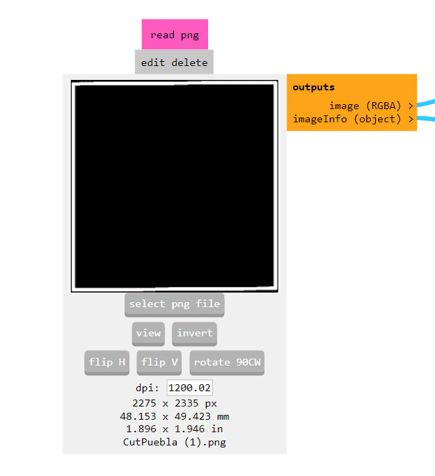
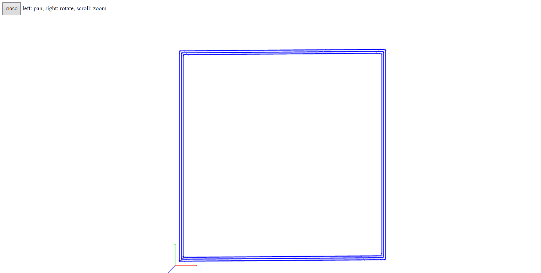
In this case, all of these changes were applied to the image "Tracespuebla." As for the "Cutpuebla" image, the only alteration needed is to invert the image so it cuts the border only. Additionally, you'll need to press the "Mill traces 1/32" button and follow the same previous steps. That's all you need to do for the "Cutpuebla" image.
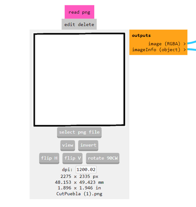
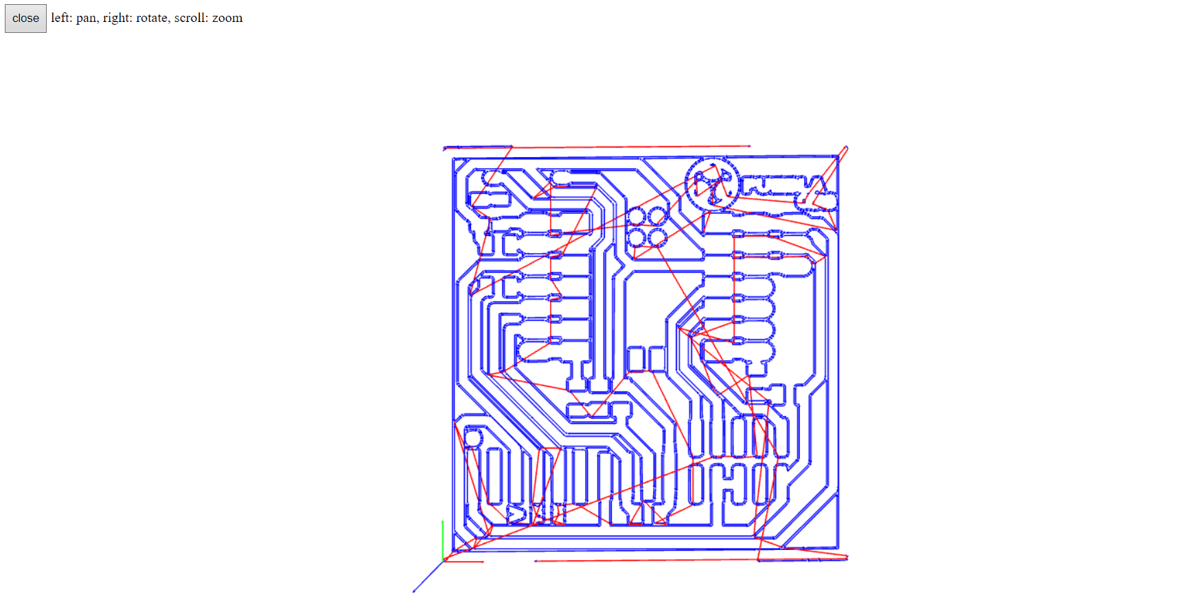
After making all the changes outlined in the previous steps and using the two PNG images named "Tracespuebla" and
"Cutpuebla," a new tab will open in your web browser. This tab will display something similar to the image shown.
Additionally, a file will be automatically created and downloaded.
Note: You can find the files and images for download at the bottom of the page.
Milling
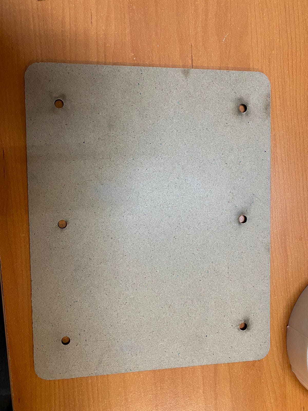
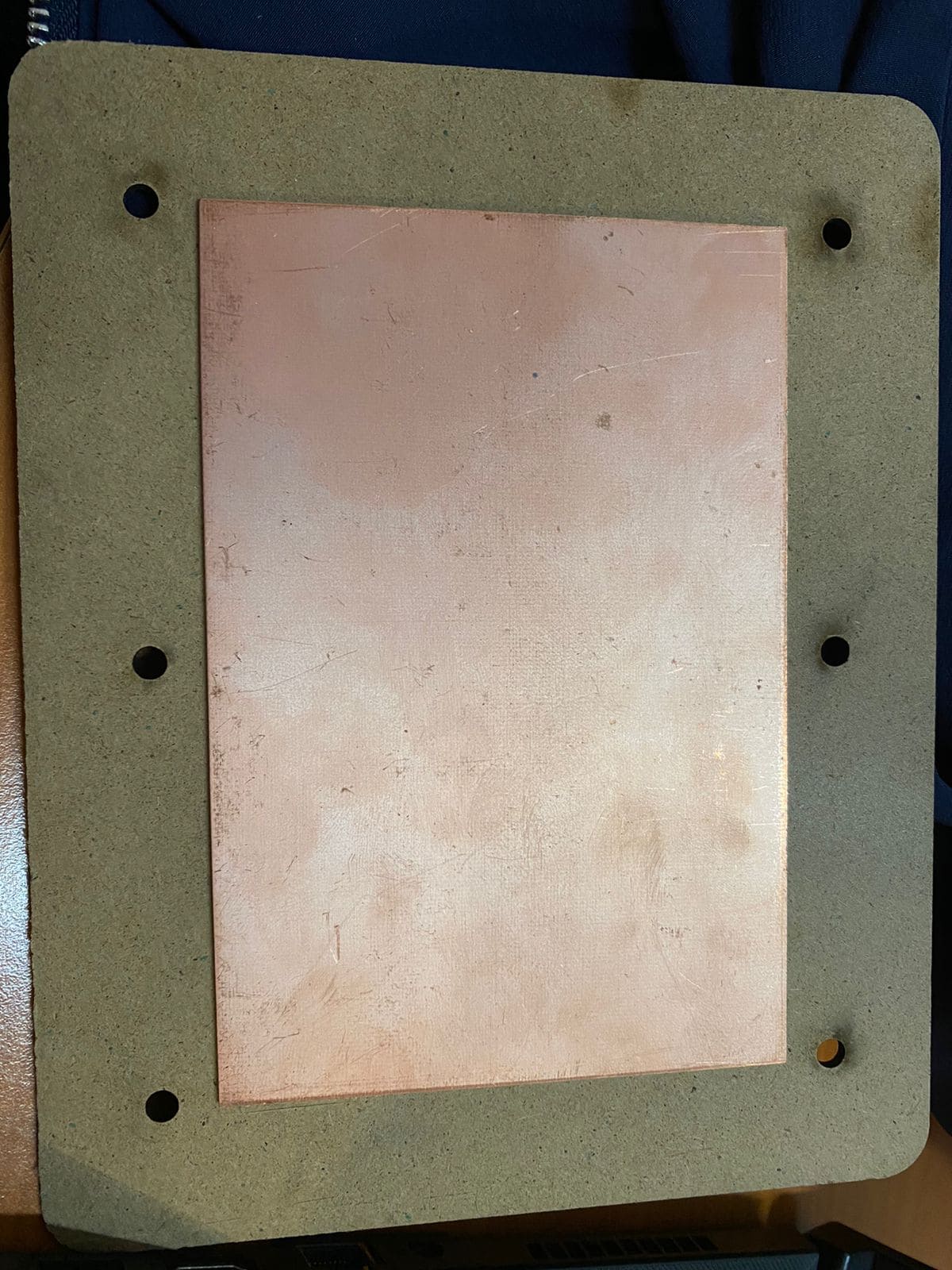
The initial step is creating what we refer to as a "sacrifice bed," which is typically made of MDF . This is essential because if there's any risk of the tool breaking through the PCB, it will first cut into the MDF rather than the metal underneath, preventing any potential tool damage. After constructing the sacrifice bed, I then adhere the copper plate to the center of the bed, resulting in the following setup.
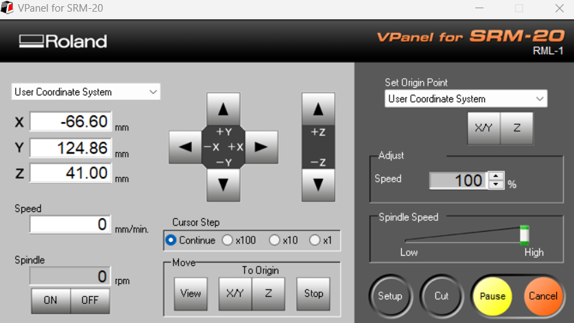
The next step is to install the software required for operating the "Roland SRM-20" machine, known as "Vpanel."
Additionally, it's crucial to download the driver to ensure that the software can recognize the "Roland SRM-20"
device. After installing the software and driver, connect the machine to your device. Once the software is opened,
it should display a user interface similar to this.
Note: You can locate the software and driver for download at the bottom of the page.
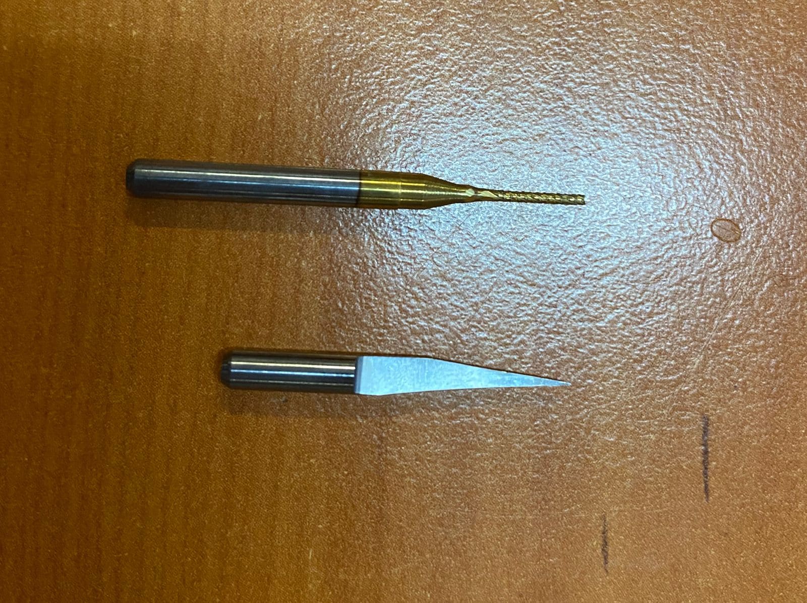
The tools utilized for engraving and cutting are as follows: a 15-degree V-bit for engraving and a 0.8 mm diameter two-flute end mill for cutting, as illustrated in the image below.
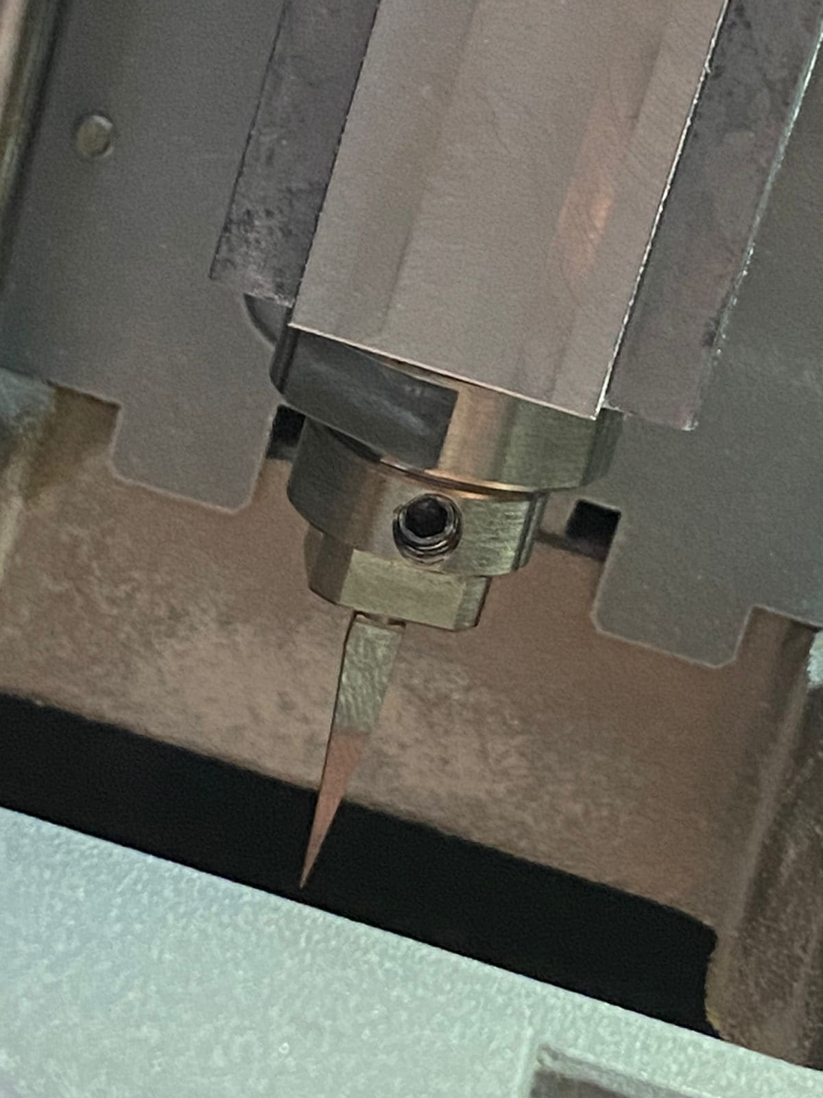
Next, secure the "sacrifice bed" onto the machine's bed. Then, position the tool in its designated location, which is typically the upper part that moves along the top. The initial tool you'll use is the 15-degree V-bit for engraving the first parts of the PCB. This tool ensures precision and accuracy in the engraving process.
There is a menu called "Cursor Setup," which offers four options for moving the machine to the desired location.
The "Continue" mode moves the machine quickly, the "X100" mode moves it 1 mm at a time, the "X10" mode moves it
0.1 mm at a time, and the "X1" mode moves it 0.01 mm at a time. These modes are activated as long as you hold
the button, facilitating movement along any of the three axes.
Next, you'll move the machine in the x and y axes to the desired starting position, preferably in one of the
corners to minimize material wastage, and set the origin point. Then, you'll position the tool by adjusting
the z-axis, moving it closer to the copper plate. Utilize the different modes to adjust the z-axis gradually
and carefully, ensuring ease of placement without damaging the tool.
If you're uncertain about the z-position, you can use the paper trick. Simply place a piece of paper under
the tool and lower the machine in the z-axis until you can no longer move the paper.
Next, navigate to the "Spindle" option and turn it on. Wait until the milling reaches the minimum rpm, which
is typically 7700 rpm. Then, switch to the "X10" mode and click twice to adjust the z-axis origin point.
Once this adjustment is done, you can raise the machine using the "Continue" mode. This process ensures accurate
positioning of the tool and minimizes the risk of damage.
After ensuring the proper setup, press the "Cut" button and choose the file you created in the mods section. Double-check that you've selected the correct file before proceeding. Once you're certain, press the "Output" button to initiate the engraving process. This will start the machine on the task you've assigned it.
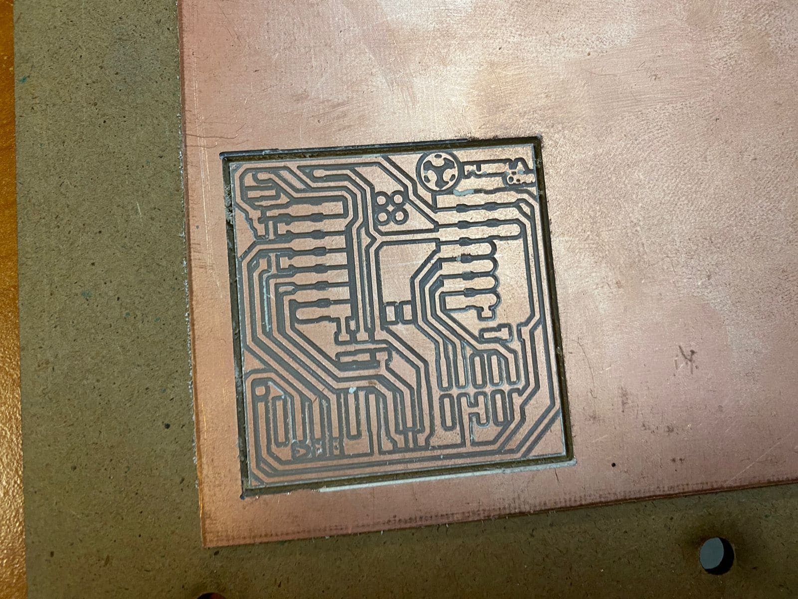
Once the engraving process is complete, clean the work area and reposition the machine for easy tool change. In this case, you'll switch to the 0.8 mm diameter two-flute end mill for cutting the border of the PCB. Repeat the same process as before to execute the final step of cutting the PCB.
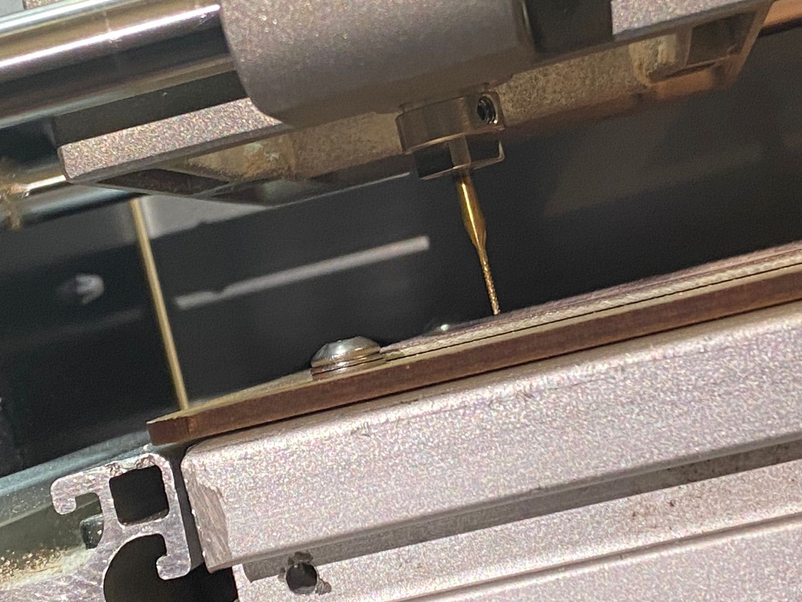
To achieve the desired outcome shown in the image below.
Soldering
Before starting the soldering process, it's essential to gather all the necessary components and tools. In this case, the basic components required are:
- 1 Xiao RP2040
- 6 1K ohm Resistor
- 1 2.2K ohm Resistor
- 3 Leds
- 1 Button
- 1 Solderin Iron
- Solder wire (as much as you need)
- Isopropyl alcohol (for cleaning purposes)
- Water sandpaper (for removing any oxidation)
Now that you have all the essentials ready, you can begin soldering. The first step is to inspect your
PCB for any impurities, dirt, or grease. Clean the surface thoroughly to facilitate easier soldering.
Next, heat your soldering iron to a minimum temperature of 350°C. Refer to the image for guidance on
where to solder the components and ensure you consult the schematic to match the right component with
its corresponding value. It's advisable to start soldering from the center and work towards the ends.
This method minimizes the risk of components obstructing your work, thus making the soldering process
smoother and more manageable.
For more detailed instructions about soldering, you can click here to visit the page.
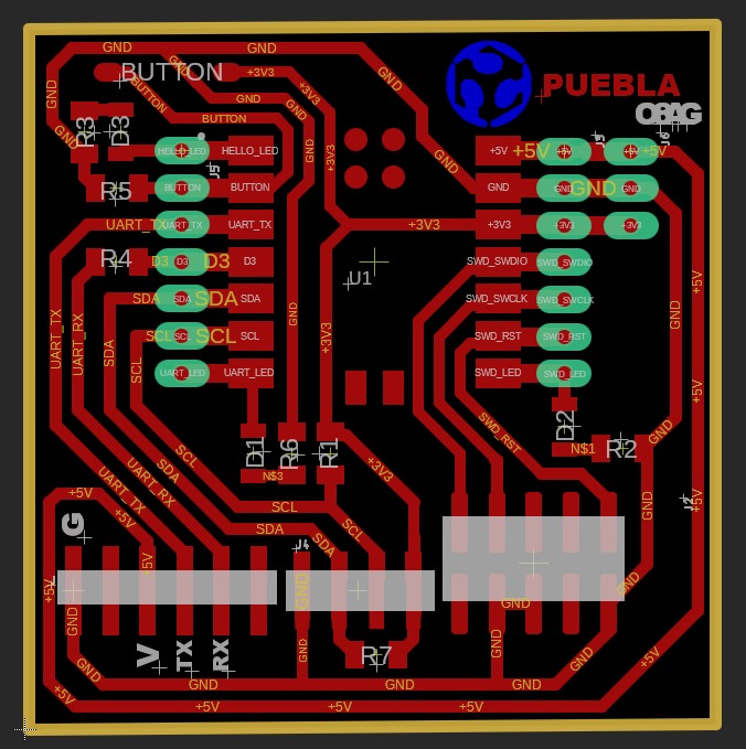
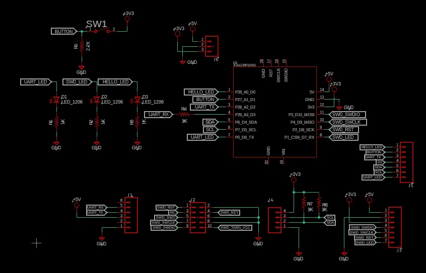
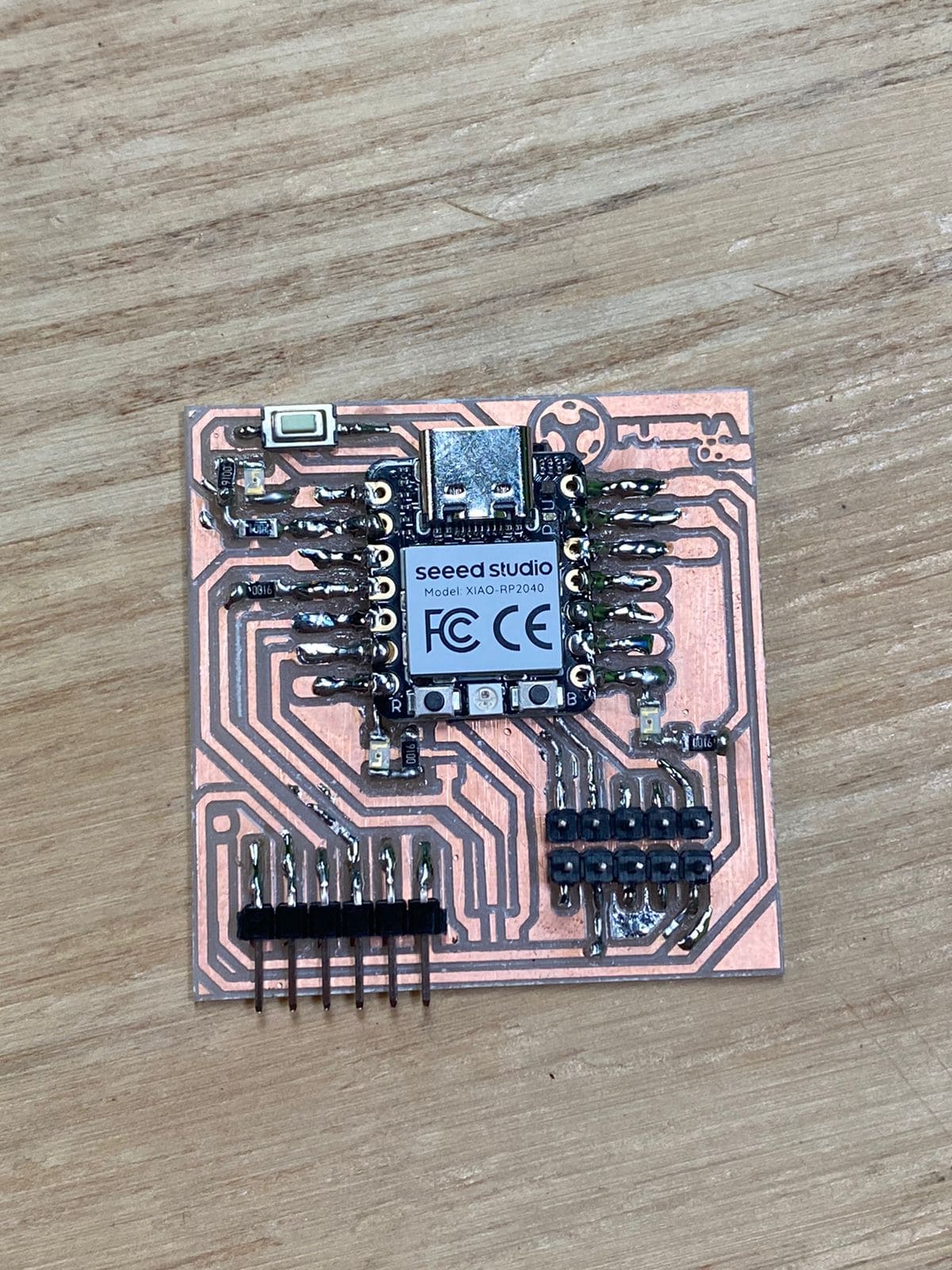
Once you've soldered all the components onto the PCB, it should resemble something like this.

Programing the PCB
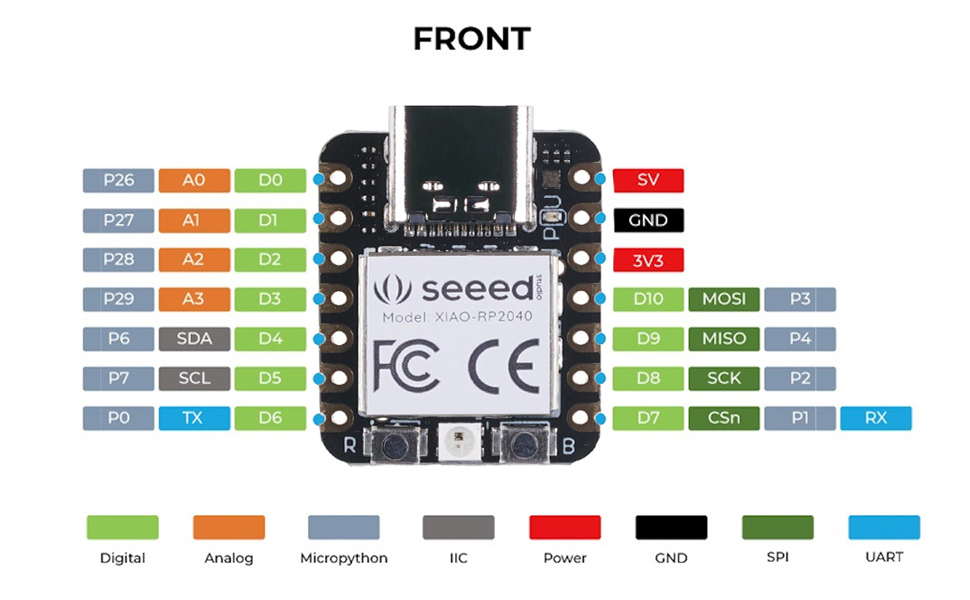
The initial step is to ensure that the board is functioning correctly and that a connection is established between the PC and the board. To do this, press and hold the "BOOT" button, typically indicated by the letter "B" on the board. While still pressing the button, connect the board to your PC. If successful, you should see a disk labeled "RPI-RP2" on the PC files, indicating that everything is ready to proceed.

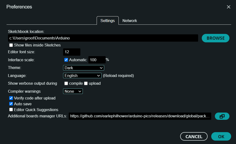
Next, install the latest version of Arduino. Then, navigate to the "Files" menu, select "Preferences," and
click on "Additional Boards Manager URLs." From there, add the following URL:
https://github.com/earlephilhower/arduino-pico/releases/download/global/package_rp2040_index.json
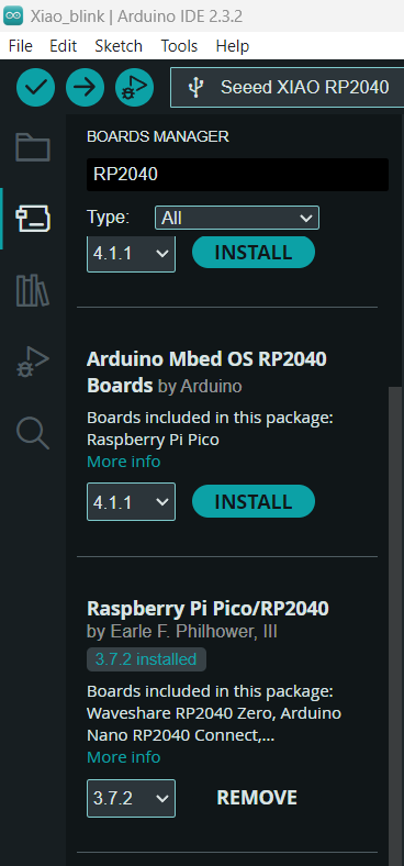
Navigate to the menu on the side of the Arduino interface. Click on the second icon from the top. Then,
click on the search bar and type "RP2040." Install the newest version of the RP2040 boards package that
appears in the search results.
Note: For more detailed information about the XIAO RP2040 tutorial
click here.
With everything set up, simply copy and paste the following code into your Arduino sketch.
To upload the code to the board, first navigate to the "Tools" menu in the Arduino IDE. From there, select "Board" and choose "Raspberry Pi Pico/RP2040" from the list. Then, specify your particular board by selecting it from the options provided, such as "Seed XIAO RP2040".
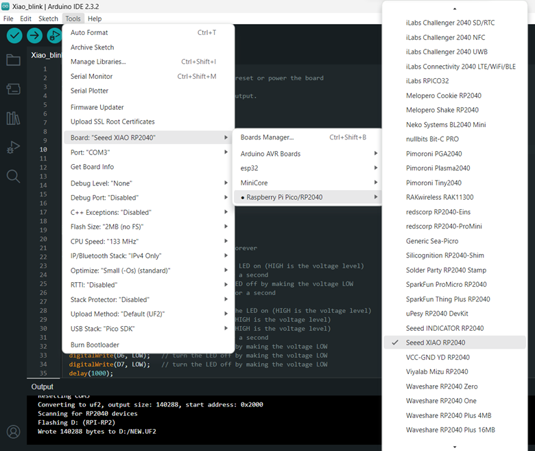
After selecting your board, navigate to the "Tools" menu again and choose the appropriate port for your board. In my case, the port is labeled as COM 3.
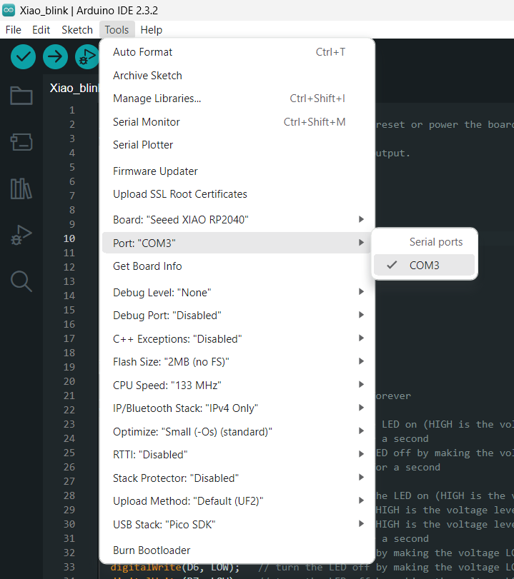
All you need to do is verify and upload the code to the board, which can be done using the options located on the top bar represented by icons of a check mark and a right arrow. Once you've verified and uploaded the code, the process should result in something like this.
