Week 10

Mechanical Design
LINK TO THE GROUP ASSIGNMENT PAGE

Group Assignment

Take a look:

- Design a machine that includes mechanism+actuation+automation+application

- Build the mechanical parts and operate it manually

- Document the group project and your individual contribution

Organization

Here is my organization to finish on time:

LINK TO THE ASSIGNMENT WEEK

Organization Of the Machine Week
Thursday 27th Initial organization, distribution of groups for the realization of machines.
Friday 28th distribution of tasks per student, purchase of materials, brainstorming of the functioning
Saturday 29th First experiments on the machine, design, frame, final operation and customer's behavior
Monday 1st Development of first prototypes in Plywood and laser cutting, board design, testing with Arduino.
Tuesday 2nd Further performance testing, purchase of new materials, addition of Relay's and other voltage control components.
Wednesday 3th Functional tests with designed plate, changed armature, addition of mechanical rail
Thrusday 4th Development of mechanical rail design, purchase of stepper motor drivers, plywood rail design plus internal circuitry placement
Friday 5th Documentation progress, operation and function tests of the mechanical rail + beverage dispenser.
Monday 8th Carry out documentation of everything developed.

PRESENT OUR MACHINE GLOBALLY

The day after the INPUT DEVICES class, we met with our instructors to give us feedback on the class. They will explain to us how the inputs work, what they are asking us for in the orders and to resolve our doubts. Here I leave the SLIDE and the VIDEO of our developed assignment.

Descripción de la imagen
Pisku Maker Video

FIRST IDEAS OF THE MACHINE

What's going to do? and Why?

This machine is developed based on a brainstorming that we had by our team, formed by:

- Maryori Vasquez

- Hans Moncca

- Jose Alberto

- Cristian

Descripción de la imagen

The main idea "PREPARE YOUR PERUVIAN DRINK", we want to develop a machine that can dispense drinks or liquids that become Peruvian alcoholic beverages flag, to achieve this the machine must do:

- Pump liquid

- Dispense the liquid through a nozzle.

- Automated programming of liquids by seconds and approximate distance.

- Controlled movement of the glass that receives liquids

Here are some sketches of the design and what we want it to achieve.

Descripción de la imagen

MECHANISM

Our group was divided into all the tasks that we were going to develop this assignment. I was responsible for the 2D and 3D design, and since I was going to be in charge of the design, I was in charge of the assembly of the machine and finally, I was also part of the testing for its development.
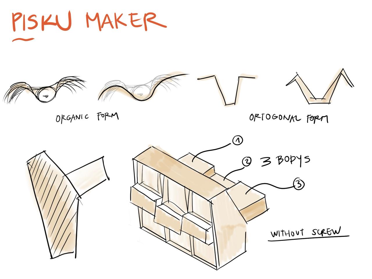
CONCEPT

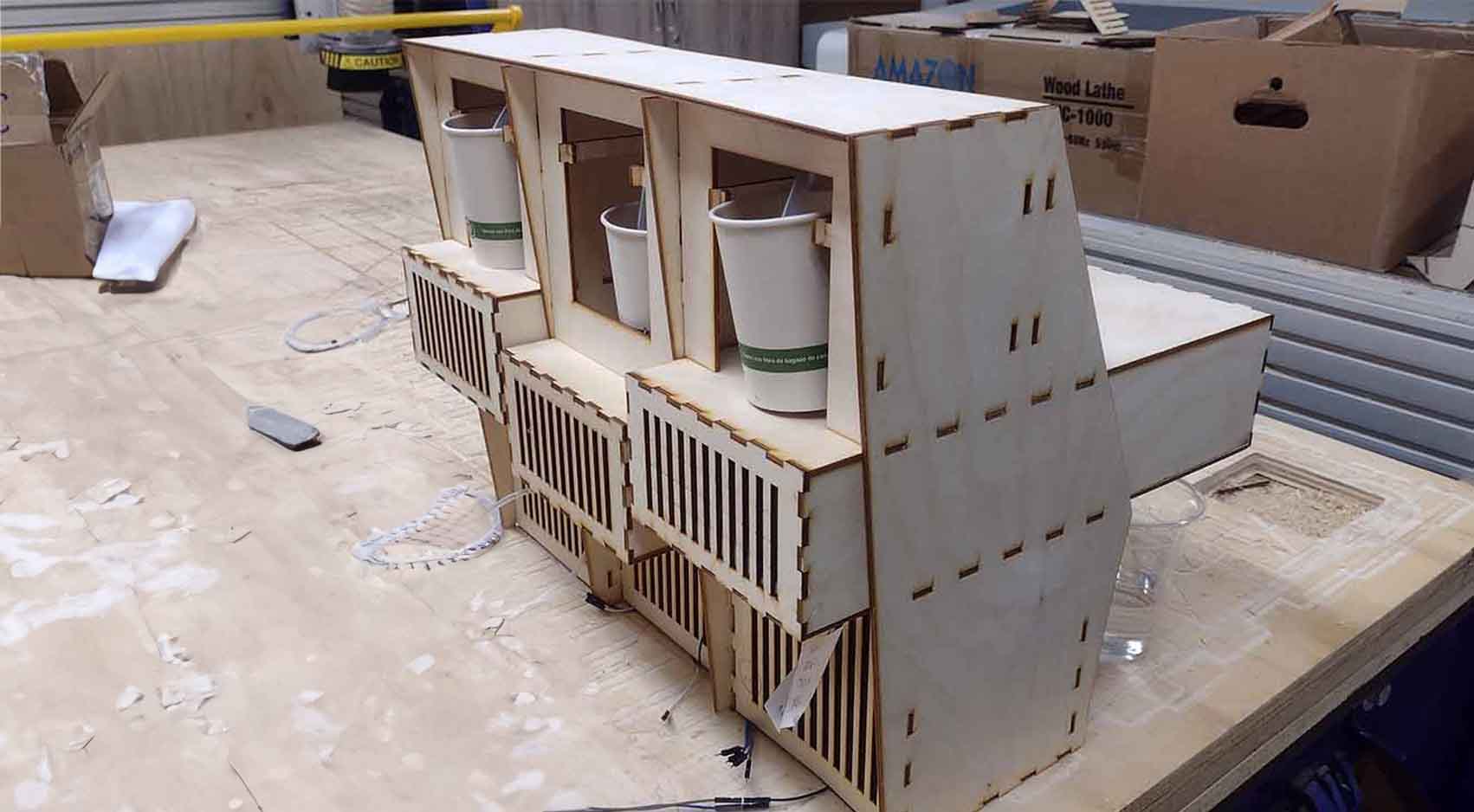
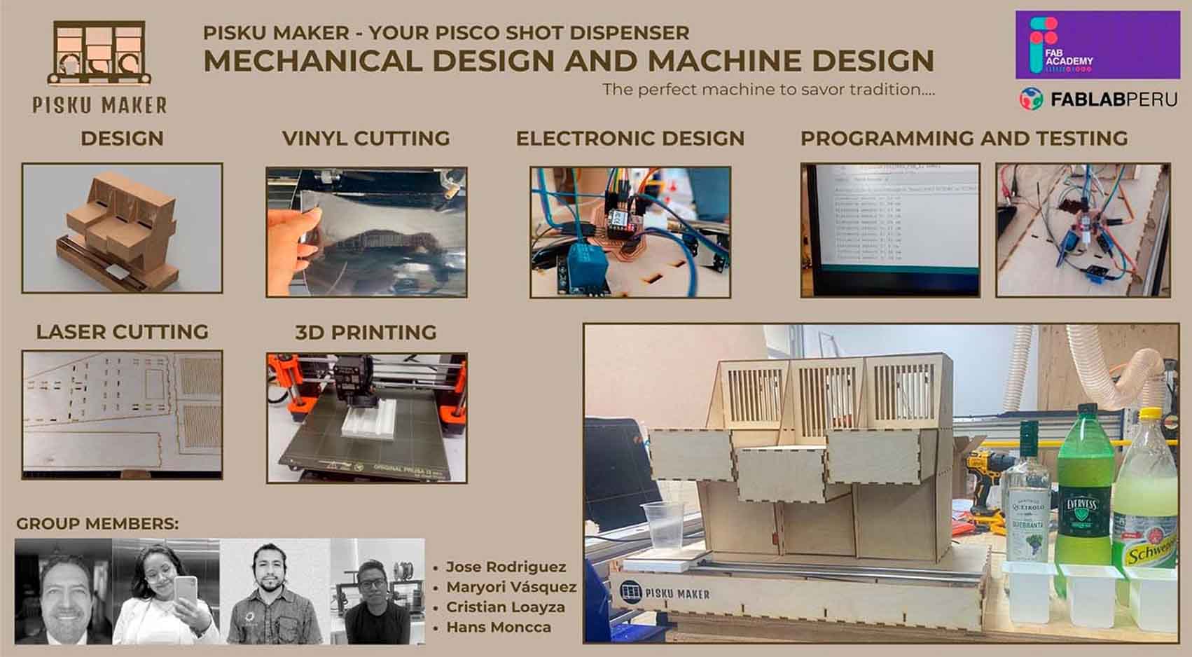
To design the machine we thought of many ways in which it could work. The truth is that we were afraid of how to start and what we were going to develop. Therefore, when recapitulating the entire FAB ACADEMY and what was done each week, we concluded that the machine should be all PRESS FIT to avoid using screws or other components since we had 3mm PLYWOOD as material. From this, we developed design sketches and what was left was one that looked like a building. The majority of the group are architects and we liked the mix between machine and architecture so much that we developed an architectural model-type machine.

SKETCH

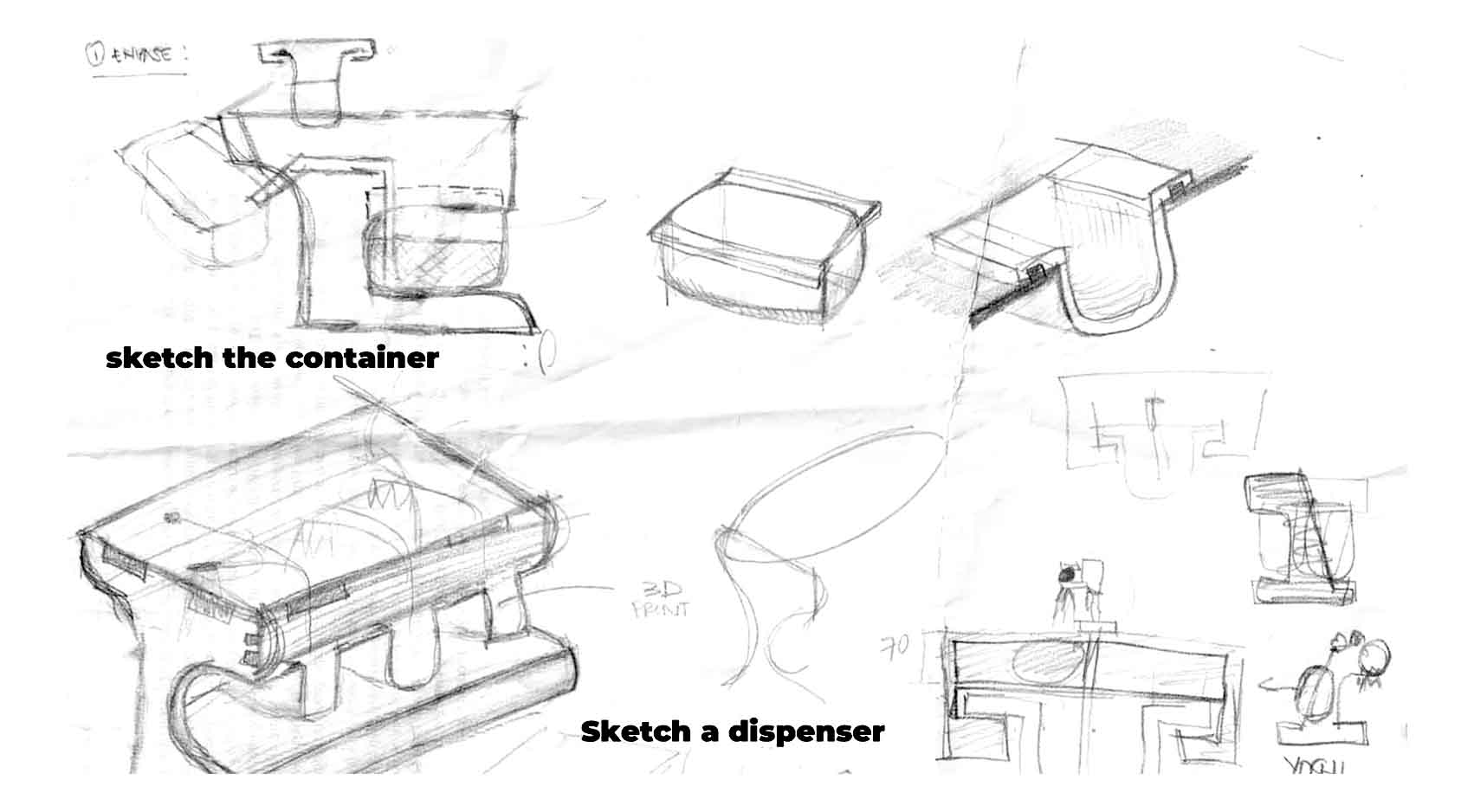
To begin the design of the machine, we began to make sketches to understand how it was going to work and how to place the components that we were going to have. Here are some photographs of sketches that I was able to recover at the time of design.

Descripción de la imagen

DESIGN AND INSPIRATION

The 3D model is inspired by the meaning of the word Pisku, which in Spanish translation is "Pisco", a legendary Peruvian drink that comes from the distilled grape, is a flagship drink of our country.

Therefore devising the meaning of Pisku in Quechua, is "Little Bird" or "small bird", thanks to this we could conceptualize our design based on rigid and strong lines, alluding to its meaning.
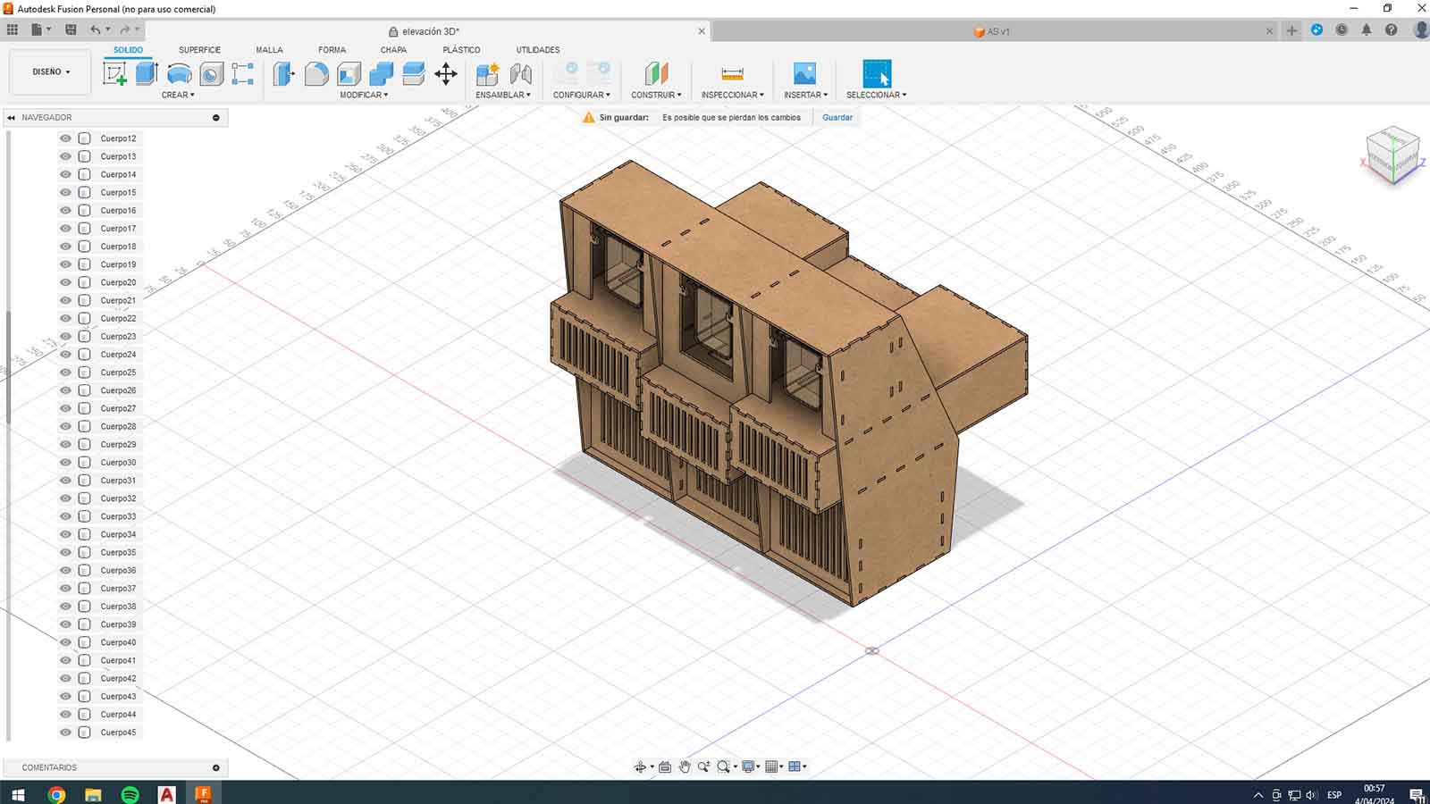
Descripción de la imagen

3D MODEL

We started to make the parts in AutoCAD and we were passing them to Fusion 360 to see the final armature of the machine.

Descripción de la imagen

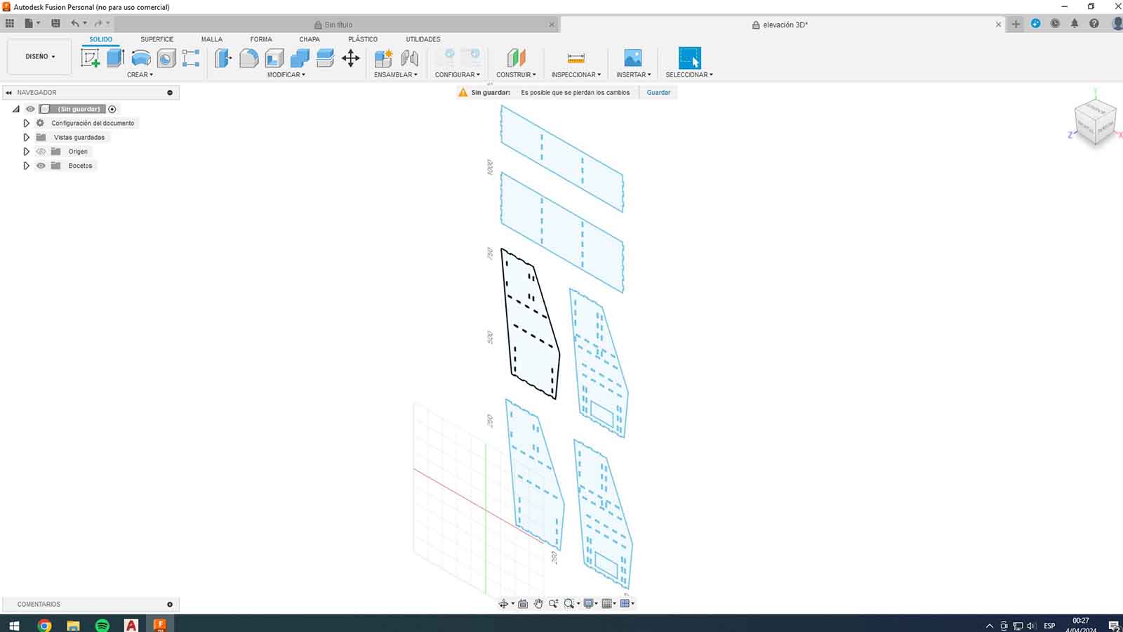
From here we start the modeling in Fusion to have a final idea, and then we move on to laser cutting to start building the structure.

Descripción de la imagen

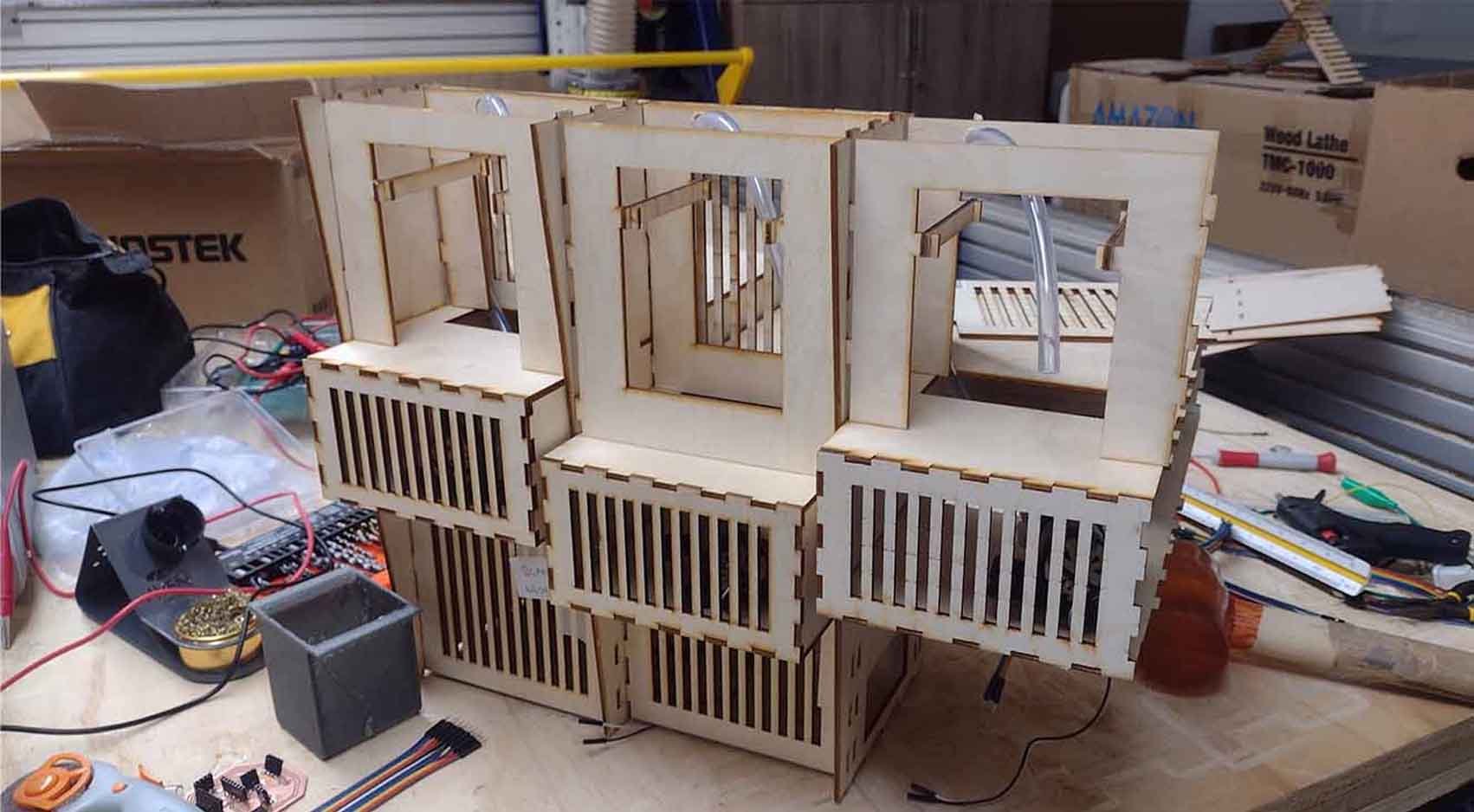
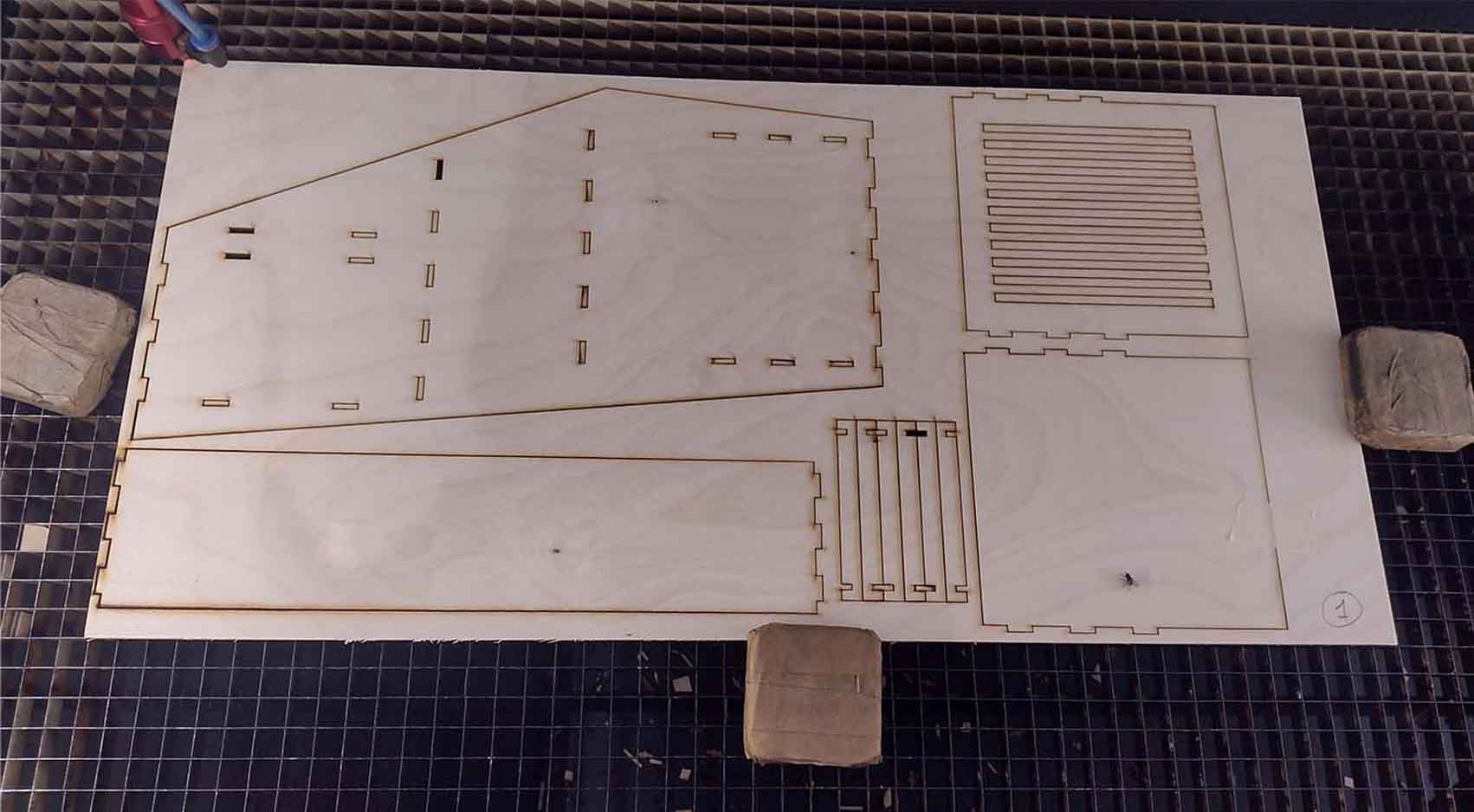
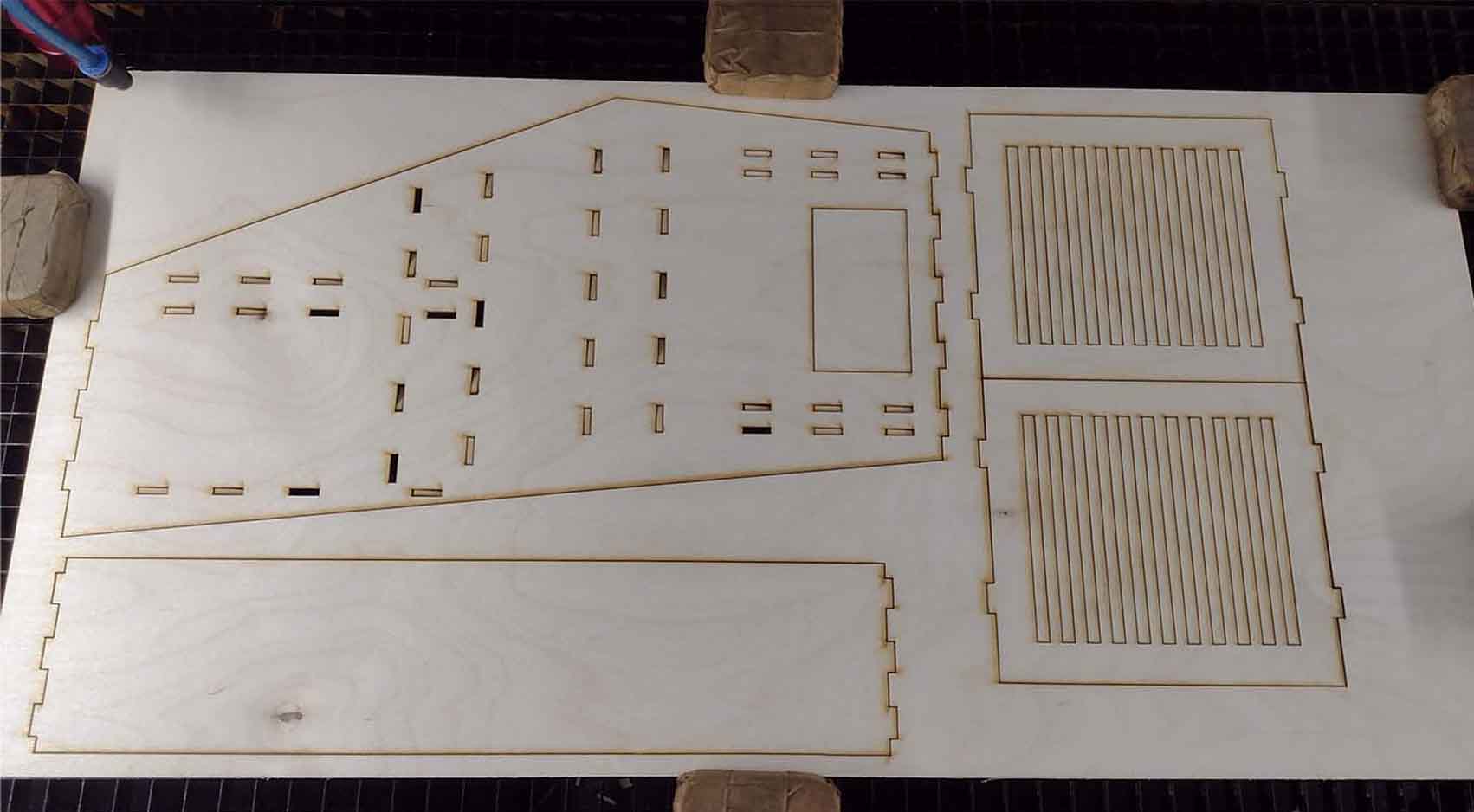
We proceeded to the quartering of the entire machine, using 3mm Plywood, the sockets were made at 2.75mm and we grouped the cuts in 9 plates.

Descripción de la imagen

Below are some screenshots of the cuts of all the pieces of the machine developed to send it to laser cut the PLYWOOD boards.

Descripción de la imagen Descripción de la imagen

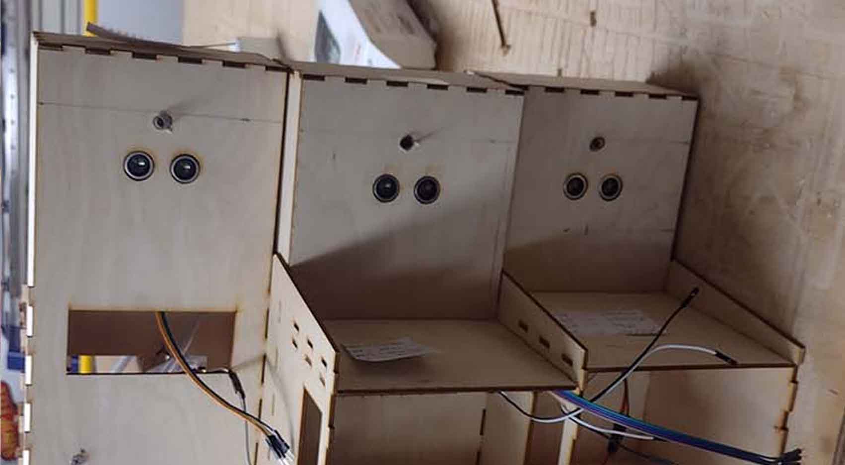
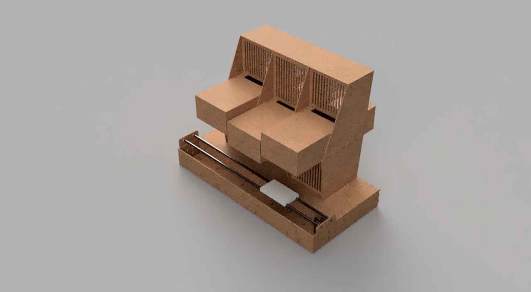
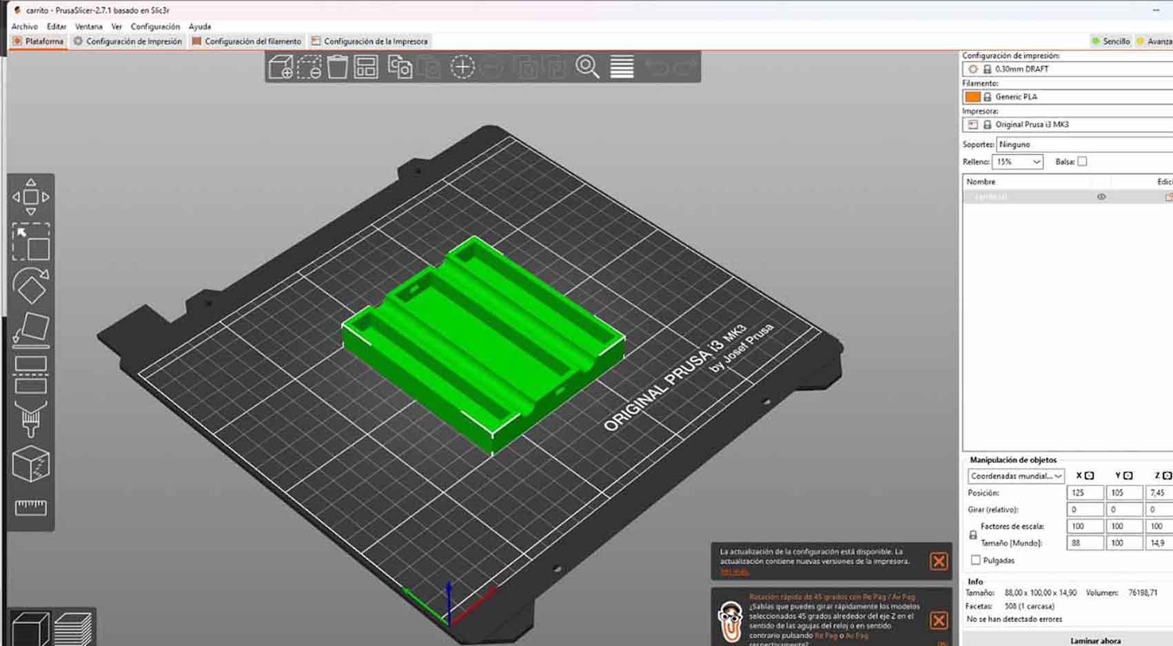
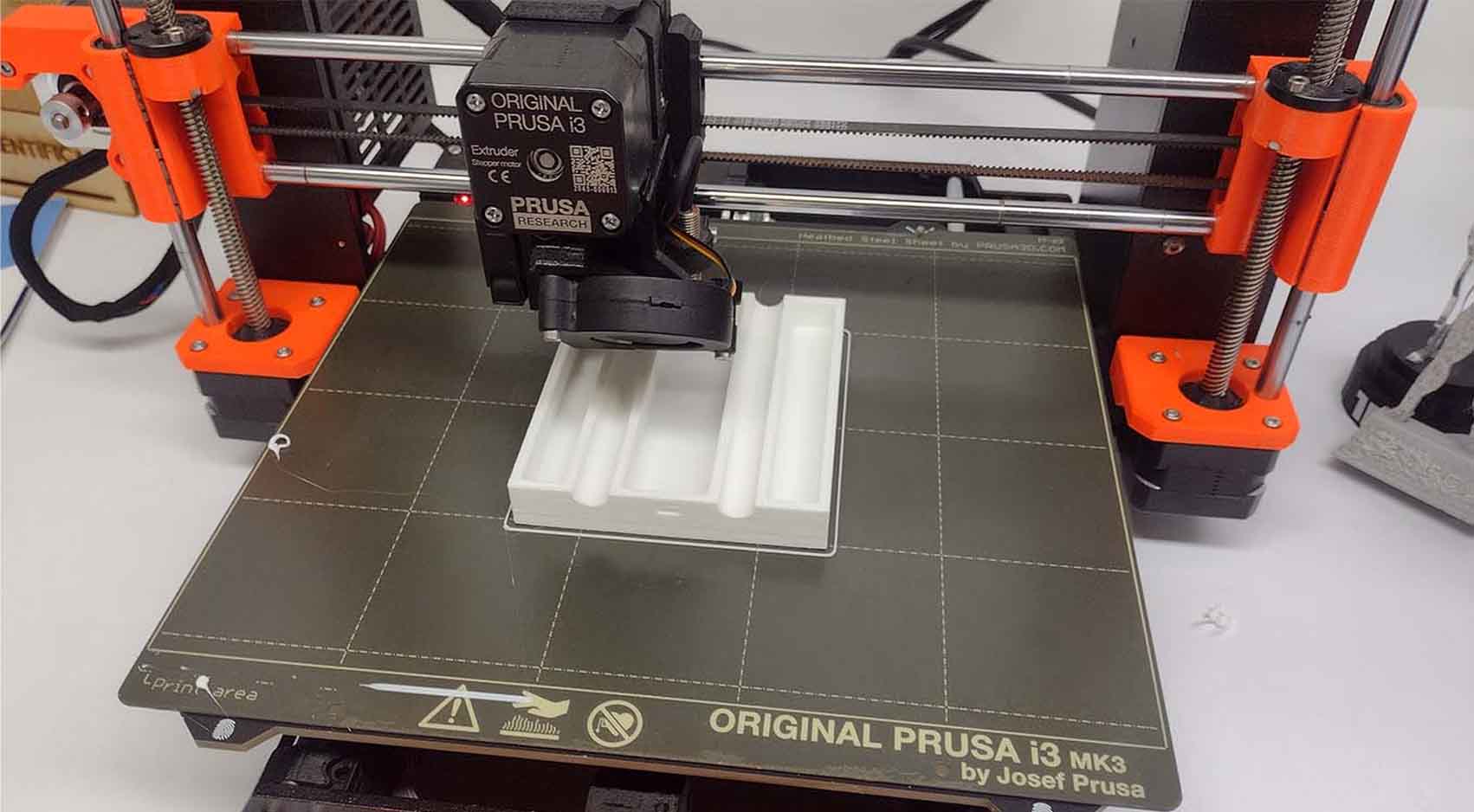
Likewise, I had some components that we were going to need 3D printed, such as the base of the glass and the liquid containers. Here are some screenshots of the procedure.

Descripción de la imagen Descripción de la imagen

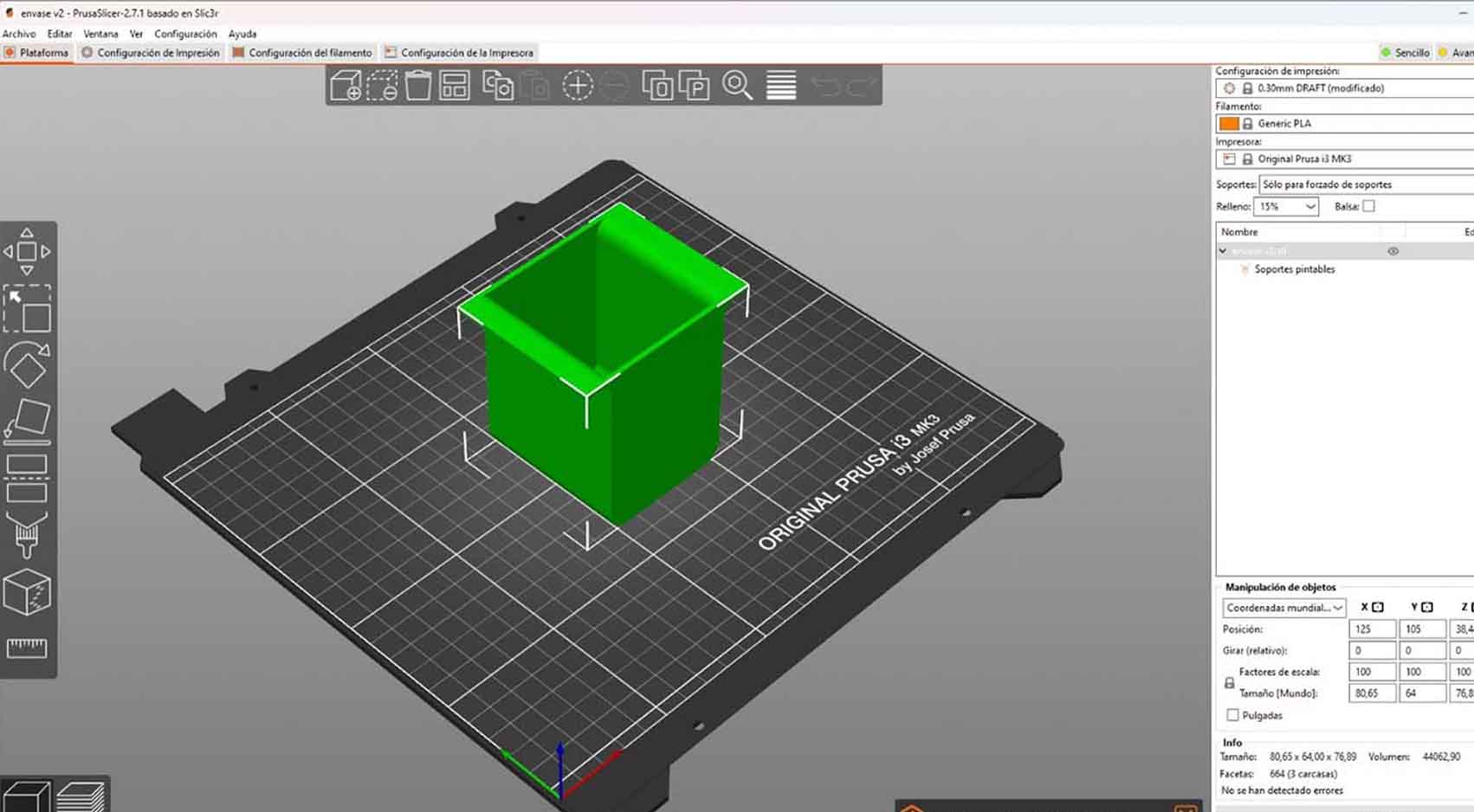
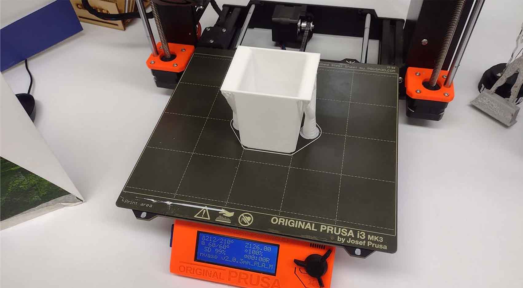
On the other hand, I also had the base where we were going to put the glasses that were going to receive the liquids to be 3D printed. This support was going to move throughout the machinery.

Descripción de la imagen Descripción de la imagen

THE LOGO

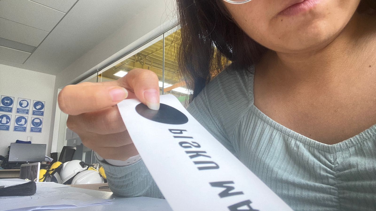
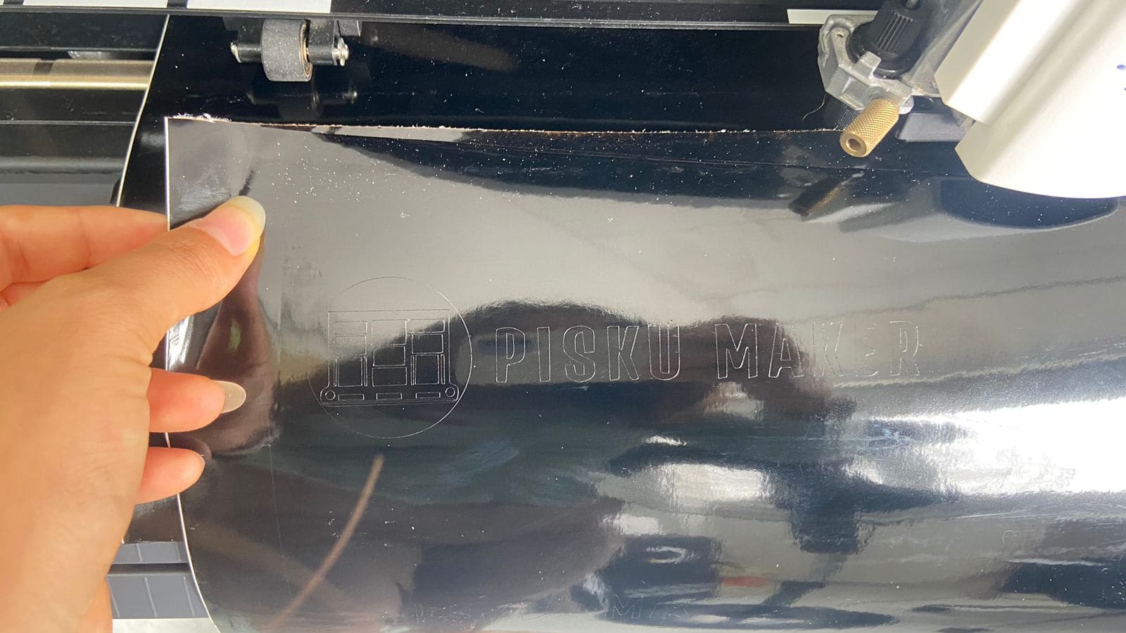
The logo is inspired by the abstraction of the machine, it was made in Illustrator, going first through the color and then being in black and white to be cut in vinyl and placed on the machine.

Descripción de la imagen

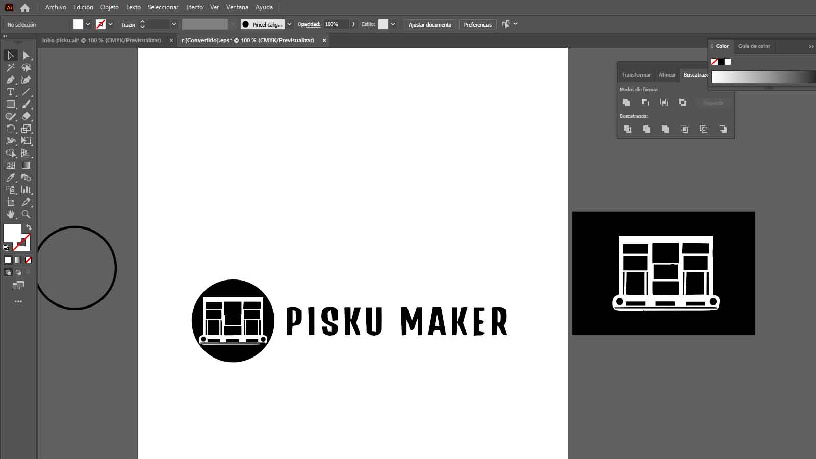
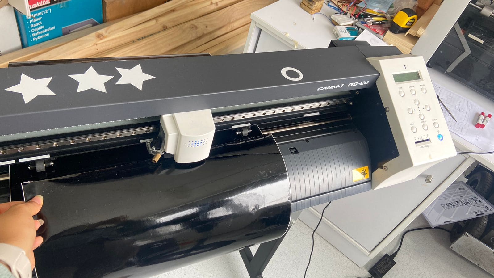
The logo was cut in black vinyl, we transferred the logo to the Cut Studio program and from this point we cut and pasted it on the machine.

Descripción de la imagen Descripción de la imagen Descripción de la imagen Descripción de la imagen

ASSEMBLY

After getting all the components cut, I went on to assemble the machine to check if the PRESS FIT fit very well and that all the parts can be assembled. I had difficulties because when assembling I had some PRESS FIT problems that took me a while to solve. In addition, I took the opportunity to place the peristaltic motors, stepper motor and some circuits because they were already ready for placement. Here are some photographs of the procedure.

First I began to assemble the base of the machine, where I located the entire stepper motor mechanism for its operation.

Descripción de la imagen Descripción de la imagen

Then I assembled the entire base adding the other pieces that this part of the machine included such as supports, sides and completing the stepper motor mechanism

Descripción de la imagen

Finally, as my colleague Cristian was able to advance the electronics part and the operation of the stepper motor, I began to place it on the base and fix it to begin the dispenser part.

Descripción de la imagen

I made a small simulation model of the base that was going to move on the axis of the stepper motor so that later, with the measurements, I could make the 3D print, here is an example of testing the travel and fixing of the steel rods

LIQUID DISPENSER

MINI WATER PUMP

For the liquid dispenser, we made some tests with the water pump model RS385, it has two ports, in and out, so that we can adjust the hose to provide the liquid on a container and can perform the pumping, thanks to this we realized that:

1. The pump loses power if the suction is performed at the same level.

2. The pump gains power if the liquid is suctioned from a higher level.

3. The pump must have safe liquid inlet and outlet ports to discharge the water.

4. The pump operates at 12V.

Descripción de la imagen

RELAYS

We discovered the RELAYS, which are nothing more than voltage stabilizers, proper to level the voltage of our pump and also prevent our card does not suffer an overload as the XIAO RP2040 provides 5V.

For this reason, we searched for a Relay module and found the following one:

Descripción de la imagen

You need the following pins

ACTUATION

ARDUINO TESTING

We did a little test run with Arduino, the diagram of the things we wanted it to perform are:

1. Liquid pumping and dispatch.

2. Actuation with sensor

3. Vessel movement on mechanical rail

Descripción de la imagen

For this reason using this knowledge, we were able to perform the first test, it was a success! attached video evidence

The tests were a success

BOARD DESIGN

For the design of the PCB we considered:

- 1K ohm resistors for the sensors.

- 3 ultrasonic sensors

- Female and male Jumper cables (many)

- 1 Arduino 1

- 2m of hose

- 3 Peristaltic pumps

BOM and Schematic for our PCB

Imagen 1 Imagen 2
Descripción de la imagen

The milling of the plate was quite fast, so it did not take more than 40min, I attach the files from here:

PISKU BOARD

Descripción de la imagen

Descripción de la imagen

FIRST TESTS

The first connections were successfully achieved, indicating that for this we had to connect the relay to the board and directly to the header 4 with the Xiao

Descripción de la imagen

AUTOMATION

The next day, I began to develop the assembly of the machine's liquid dispenser. First I started on one of the sides, where I began to place the peristaltic pump together with its entire mechanism and I also located the ultrasounds that we used so that I could read the glass that was going to run through the machine.

Descripción de la imagen

To verify that the entire operation of the liquid dispenser is working correctly, I did a small test with the pump to see if there were leaks or any problems with the mechanism, but everything was fine, here is a video of how it works.

I continued assembling the machine and checking the operation of each sector of the machine. I also began to connect the pump and ultrasound circuits for the electrical part. Here are some photographs of the work.

Descripción de la imagen Descripción de la imagen

Here you can see what it looked like from the bottom of the machine dispenser, where we have 3 ultrasounds for each liquid, 3 peristaltic pumps along with their electrical connection ready.

Descripción de la imagen

Finally, at the end of the day I was able to finish assembling the machine, I really liked the process since I learned many things that we could improve. Now to unify both parts of the machine.

JOINT WORK

After finishing the entire assembly of the machine, I began to carry out tests with liquids from the dispenser, we have not yet tested with the built-in base to avoid damaging the circuits due to technical failures. Here are some test videos and everything worked very well.

Descripción de la imagen

APPLICATION

After checking all the operation, automation and programming of the machine, we proceed to carry out the last tests of the machine to achieve the objective.

We were able to observe that the machine worked well but the configuration for synchronization had small errors and the ultrasound reading was not as accurate. We reviewed the programming and automation to achieve the objective.