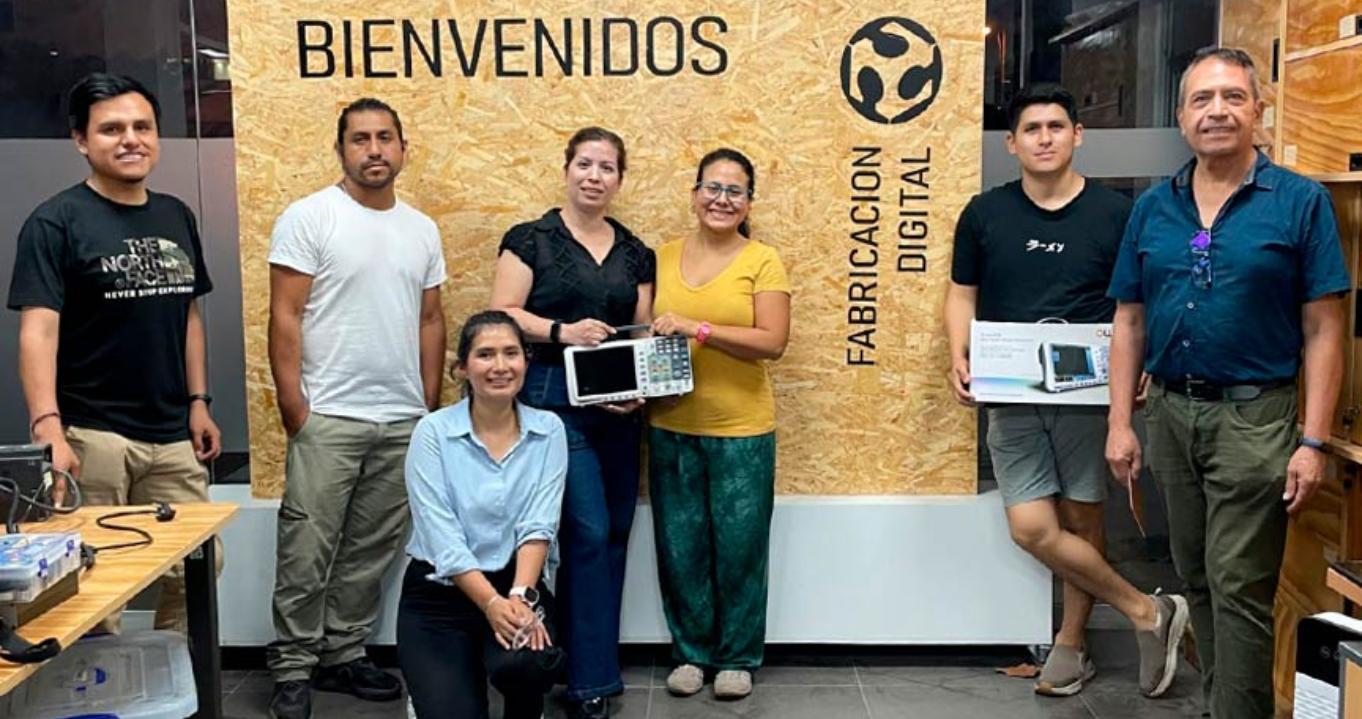
Electronics design

This week we will be designing our first custom PCB board, I'm excited...

The assignment was:

Group assignment: use the test equipment in your lab to observe the operation of a microcontroller circuit board send a PCB out to a board house.

Individual assigment: use an EDA tool to design a development board to interact and communicate with an embedded microcontroller, produce it, and test it.

Extra credit: try another design workflow. Extra credit: design a case for it. Extra credit: simulate its operation

Group assignment

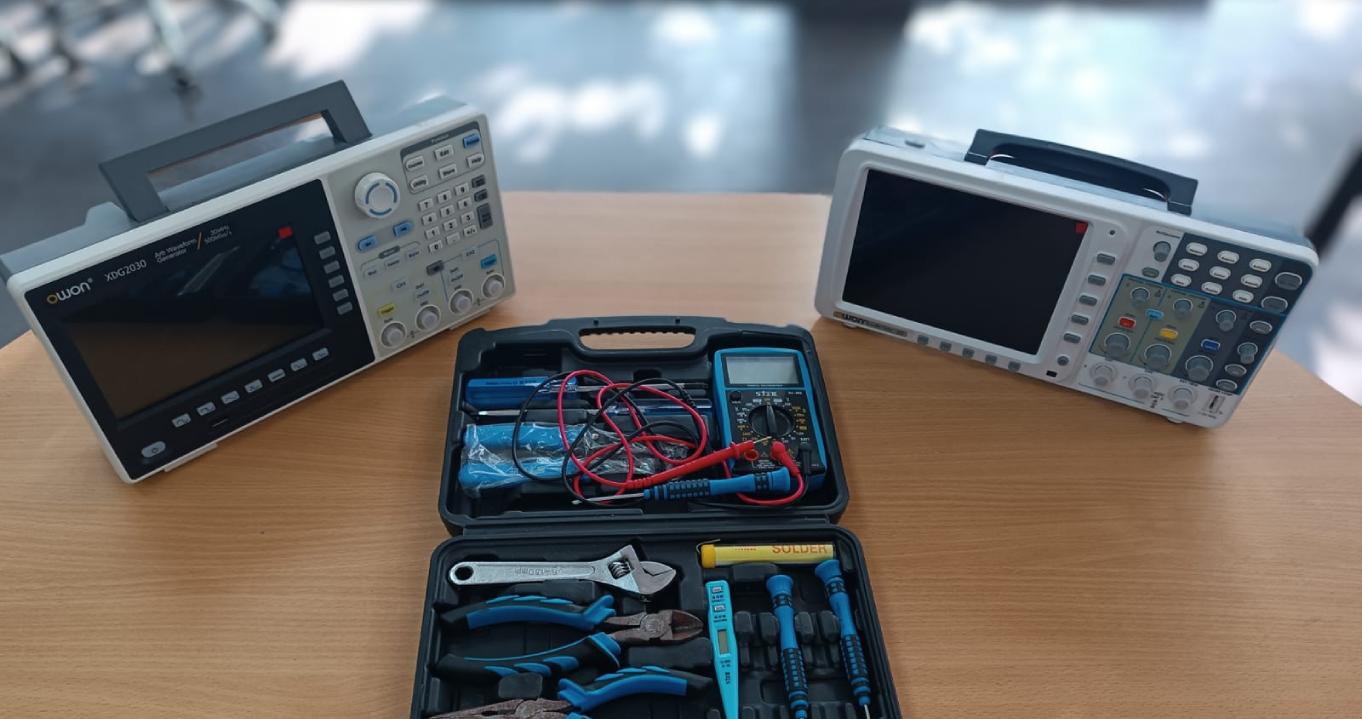
For this group assignment we visited the IEST Simon Bolivar Fab Lab located in the port of Callao.

You can see the documentation on the group's web page

What did you learn?

The importance of the oscilloscope and the multimeter as essential basic tools for electronic work.

Learn to visualize the graph as a result of the electrical variation in a given time.

The multimeter allows us to measure the electric current that flows (continuity) from one point to another.

With the use of these tools we can validate the design of electronic circuits.

Individual assignment

Steps before design

The first step is to navigate to the Kicad website and download the latest version of the software.

You should select the software according to your operating system.

In my case I will download the latest version 8.0.1 for windows.

Click on Github to download x86-64-bit

An automatic download window will open.

It was time for installation.

Design using Kicad

This is the first window when you open the software

We create a new project inside a folder.

Name the project and save it

Once saved you will see on the screen the project created with two files.

nameproject_pcb

nameproject_sch

To design we will first work in the Schematic Editor

click the Schematic Editor icon.

This is the Schema Editor environment

Important tools:

1. select items

2. Add symbols

3. Add power symbols

4. Add a wire

First we must Download the library from github

Install the fab library in Kicad.

Enter the Symbol Editor.

File->Add Library

Select global to be able to use the library in all projects.

press ok.

We add the symbol library named fab.kicad_sym

press open

closed Symbol Editor

now we start with the design of our pcb scheme.

Finished designing the schematic of our pcb:

Tools->Update PCB from Schematic...

In this window

total warnigs: 0; errors 0

Press Update PBC

select close.

In this window

we will sort the components and trace the routes

Result 3D viewer

PCB board milling and soldering

PCB board milling process

Result pcb cut on a bakelite board

component soldering process

Fabrication of my first PCB called CRISDUINO

I use the Xiao RP2040 microcontroller

I know it's not a marvel but patience, it's my first PCB designed and manufactured by my hands.

Test

We wrote a few lines of code to test the operation of Crisduino with an SG90 servo motor.

                    #include <Servo.h> //Import library

                    Servo servocrisduino;
                    
                    void setup() {
                        servocrisduino.attach(D0);
                    }
                    
                    void loop() {
                        servocrisduino.write(0);
                        delay(2000);  // wait 2 seconds
                        servocrisduino.write(90);
                        delay(2000);  // wait 2 seconds
                        servocrisduino.write(180);
                        delay(2000);  // wait 2 seconds
                    }
                    

Brilliant!!! the Crisduino works...

What problems did I have and how did I solve it?.

Problems with soldering, trembling hands and nerves, I solved it with a lot of practice and patience.

I had to cut the components such as connectors since in Peru there are no connectors of this type.

Download files

Here we can find and download the design original files