Wildcard Week
Individual Assignment
Design and produce something with a digital process (incorporating computer-aided design and manufacturing) not covered in another assignment, documenting the requirements that your assignment meets, and including everything necessary to reproduce it.
Table of Contents
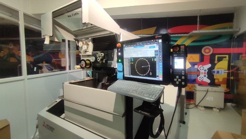
Mitsubishi MV1200-S Advance
Something I haven't worked with personally was metal cutting. Also I haven't personally worked with it during the machine week as well. So I thought I will cut something in metal for myself like a keychain or a locket. For metal cutting we have Water Jet and EDM at our lab. I have been curious about the working of EDM and I chose it to study its operation and handling.
Wire EDM and its working
Wire EDM (Electrical Discharge Machining) is a specialized manufacturing process used to cut hard metals that are difficult to machine with traditional techniques. This process uses electrical discharges (sparks) to cut through material, offering the ability to produce intricate and precise contours with a high degree of accuracy.
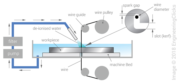
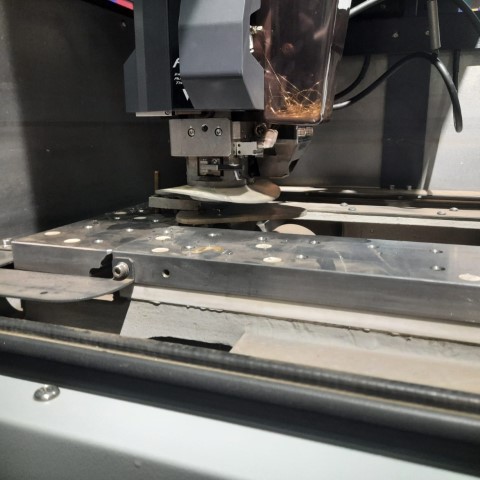
A thin wire, typically made from brass or stratified copper, acts as the electrode in Wire EDM. This wire is continuously fed from a spool through the workpiece, which is submerged in a tank of dielectric fluid, usually deionized water. The continuous movement of the wire prevents wear at any single spot during the cutting process. The wire is charged to a voltage that generates an intense electric field between the wire and the workpiece. When the electric field becomes sufficiently strong, a spark jumps across the gap, melting and vaporizing a tiny portion of the workpiece. The dielectric fluid surrounding the process cools the area and flushes away the removed material, keeping the cutting zone clear and preventing the metal from re-adhering. Additionally, the fluid insulates the wire and workpiece, ensuring that sparks occur only in the desired locations. A computer controls the machine, dictating the wire's movement along a programmed path, which allows for the creation of highly complex and detailed cuts with precision.
Features
1. Machine Travel: 400 x 300 x 220mm
2. Maximum Workpiece Dimensions: 810 x 700 x 215mm
3. U/V Travels (from center): ±60 x ±60
4. Taper Angle at Thickness: 45° at 1.8"
5. Wire Diameter Possible: 0.1-0.3mm
6. Auto Threader Technology: It features an improved non-contact Cylindrical Drive System with a non-contact auto-threading system, which allows for fast threading and re-threading of the wire, enhancing productivity. Here, we are using brass wire of 0.25mm thickness.
7. Improved Cutting Speed and Accuracy: The MV1200-S Advance boasts high cutting speeds and excellent surface finish quality, making it suitable for demanding applications in aerospace, tool and die, medical, and other industries.
8. Energy Efficiency: This model is designed with energy-saving features, reducing power consumption compared to older or less advanced models.
9. User-Friendly Controls: It includes Mitsubishi’s M700 series control system, which provides a user-friendly interface, advanced programming capabilities, and easy integration with CAD/CAM systems.
10. Advanced Filtration System: The machine incorporates an advanced filtration system that helps maintain clean dielectric fluid, crucial for maintaining the precision and quality of cuts.
CAD
So I thought of designing a keychain for myself with my name. I took Inkscape and typed in my name THEJ and found a font I liked. The font I'm using is BatmanForeverAlternate. I changed the document properties to 35cm x 35cm since I wanted the keychain to be small. Then I exported the DXF file of this.
.png)
Next, I opened the DXF file in Fusion360 and then extruded the letters and converted the bodies to components so I could move them around and arrange them like this. I added a small hole as the keychain holder.
.png)
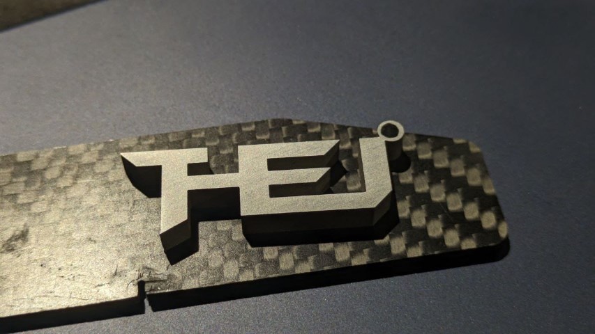
This is the expected output
.png)
Production Process
Next step is the production of the design.
Drilling
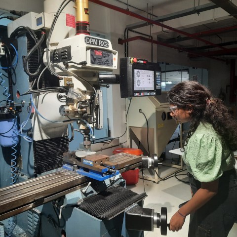
During week twelve of moulding and casting, I was introduced to 3D milling by DPM RX2 Vertical Milling Machine. Therefore, I'll be implementing the same workflow for setting up CAM. I've generated program for 5mm drill bit which is the hole through which wire will be inserted for the cut, as well program for 2.5mm drill bit which will be the keychain hole.
So I've taken Aluminium piece of 5mm thickness and clamped it to the machine.
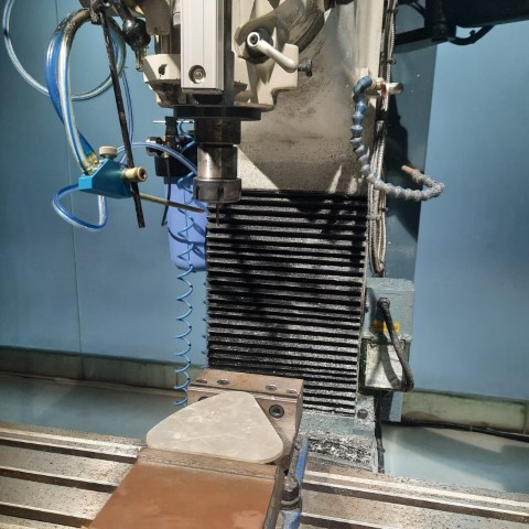
Using 5mm drill bit, the first hole was drilled.
Using 2.5mm drill bit, the second hole was drilled.
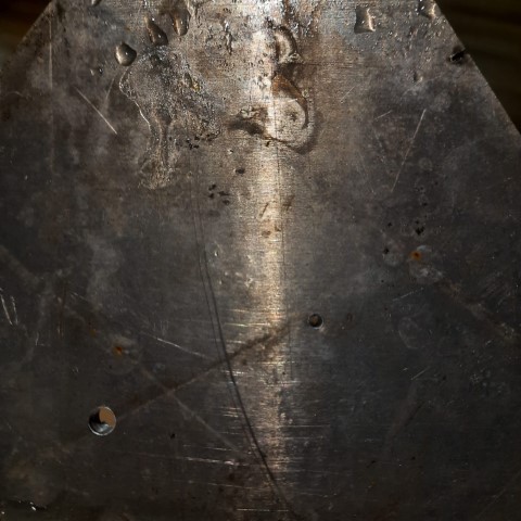
Here's the result
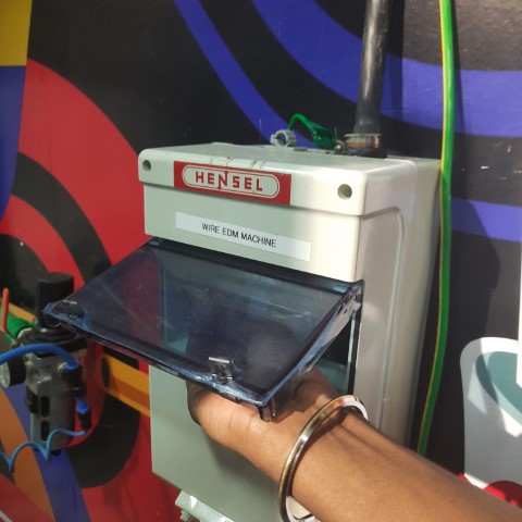
EDM Setup
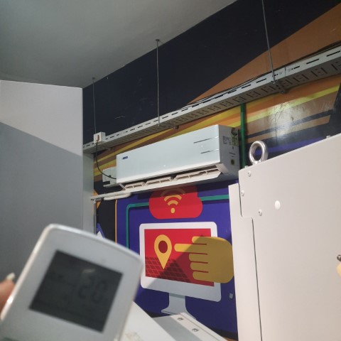
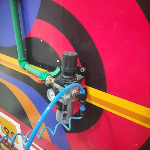
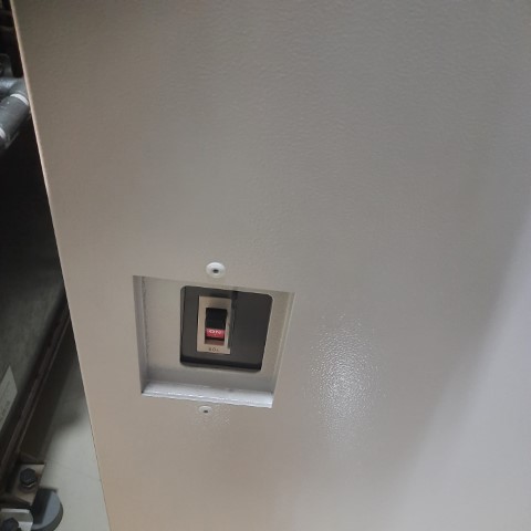
We have our EDM set up in a seperate room. Before turning on the machine, switch on the AC so the room is cooled down. Next, make sure all the switches are on, additionally the pump.
Work Setup
Use the clamping tool to set up the workpiece into the machine
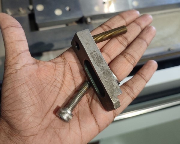
Using 2 sets of the tool, the workpiece was set up. While clamping the workpiece there is higher chance that the orientation of the workpiece is not proper ,i.e., there will be a slope. The machine has a feature where it can measure the slope and adjust the cutting file accordingly.
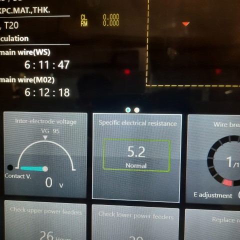
There are two things that should checked mandatorily before proceeding to operations.
1. The value of Specific Electrical Resistance is in the normal range.
2. The button G92Clear on top is in blue colour. Otherwise, click on Reset till its blue.
The Mitsubishi MV1200-S Advance comes with a pendant, which serves as the control interface for the operator to interact with the machine. This pendant includes various controls and displays essential for operating the machine, setting up jobs, and monitoring the process. It is a critical component, enabling precise and easy manipulation of the machine's functions.
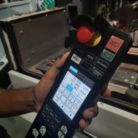
• AT Insert: To insert the thread automatically
• AT Cut: To cut the thread
• AT Test: While orienting the nozzle to the hole to insert the thread, by pressing
this button, water will flow down through the nozzle thereby making it
easier to position the nozzle right through the hole.
• Pipe Up and Pipe Down: To manually insert the wire during failure in AT Insert
• High, Med, Low: To set the speed of the movement of the nozzle while
manually moving
• +X, +Y, +Z and its negatives: To move the nozzle in corresponding axes
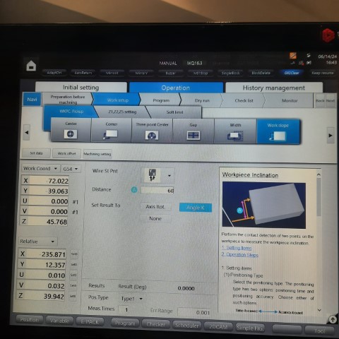
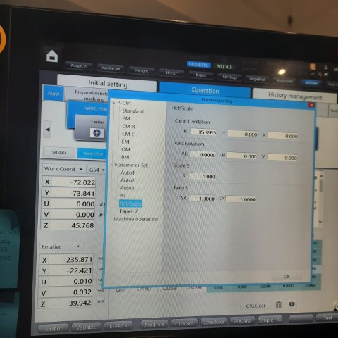
Work Slope
Since the workpiece was set up with a slope, it is necessary to calculate the slope.
Press on AT Insert to load the wire. Next, click on Work Slope option available at "Work Setup". Next, select the progress method required according to the placing of the workpiece and press on "Start" in the pendant to find the slope. Once done, click on Machining Setting > Rot/Scale to see if the value of K (slope) is set.
Calculating Origin
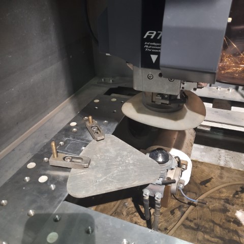
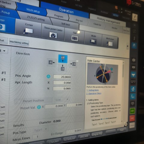
Before starting each operation, the origin or the starting point has to set. In this case, I have already drilled the holes from where the operations are to begin. For that, first we move the nozzle right above the circle with the help of Pendant. To see if it is on the correct position, press on "AT Test" to see if the water pass right through the hole. If it is proper, then insert the wire with "AT Insert".
Next, click on Work Setup > Center to find the center of the circle. Make sure to give the position angle as 20.0 deg. One more thing to notice, while giving input number make sure to add the decimal point right after since it doesn't store the value otherwise. For example, here I gave 20.0 deg instead of 20 deg.
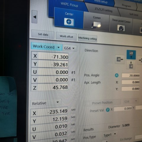
Press on "Start" after providing the detail and once completed, set the value of X and Y coordinates as 0.0
CAM
Next step is to do the CAM for the operations. Click on 2DCAM at the bottom of the screen.
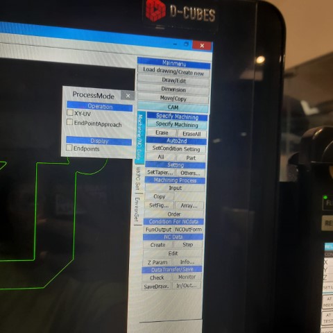
Click on "File" to insert the .dxf file. At the right side, there are different options available. Click on Specify Machining.
Press on Shift and then move the cursor to the circle to see a crosshair appearing and then click on it to define the starting point.
Next click anywhere on the profile that is closer to the starting point to show the path.
Next, click on SetCondition Setting to define the operation and workpiece material.
• Workpiece Material: Aluminium
• Workpiece Thickness: 10mm (Actual thickness of the block is 5mm, but it
is better to choose the closest value from the option)
• Die/Punch: It depends on each operation. We have a note stuck to the
system in order to avoid the confusion between die and punch. Here, mine is Punch.
• Nozzle Gap: I selected Opn-U&L where the upper and lower nozzle will
align itself to the gap.
• Find Surf: It defines the surface finish. Lower the number, greater the
surface finish. I chose 3.0-1.6 as it is enough for my work
and also because the lesser the number, more time-consuming the
operation becomes.
• No.Cuts,
Surface Finish and
Avg. Speed: Depends on the operation, One pass would be enough since I'm just cutting it out.
Once data is provided, click on "Search E-Pack" and click "OK".
press All option under SetCondition Setting to apply the parameters to all profile.
Click on NC Data > Create to generate G-Code. Then, click on Data Transfer/Save to save the G-Code.
Note
In the G-Code some edits has to be done. to do so, before saving, click on "Open File" and add M91G54 before the program and delete G92X0Y0 code from the file.
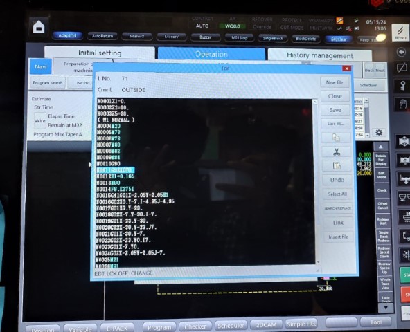
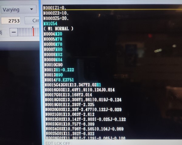
M91G54 is to set a predefined point as the origin for the part being machined. In this case, the center of the circle. The code G92X0Y0 is a command used in CNC (Computer Numerical Control) programming to set a temporary zero point or offset for the X and Y axes at the current position of the tool. Both the code typically serves the same purpose but we have been advised to choose the first because the latter can only be used in the situations where the initial point is set in which case if it is made to travel from one point to other, there is chance that the operation fails.
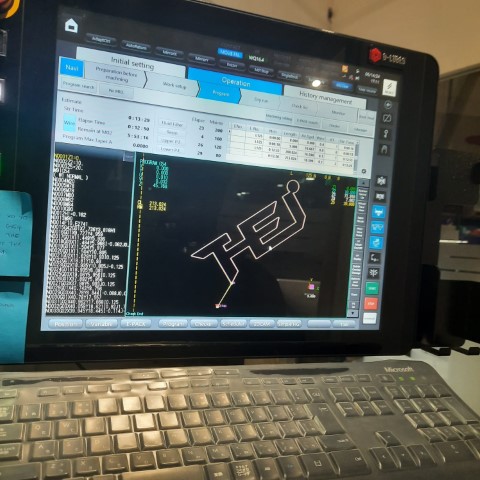
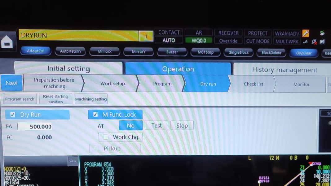
Next, open Program available at the bottom of the screen. Click on Program search to load the file. It is always better to try Dry Run first before moving to the actual machining. For that, click on Program > Dry Run and press "Start". You will be able to see the path so that you could clarify any errors.
If it turns out to be right, then next we have to set the Z limit. The upper nozzle should be as close to the workpiece. It can be achieved with the help of Pendant. Once it is closer, press and hold "Z limit" on the Pendant. Setting the limit is beneficial because once set, even if you change the Z position while taking out the pieces in between the process, while lowering down, it automatically stops at the set limit.
Once done, go to Program and press "Start" to start the process.
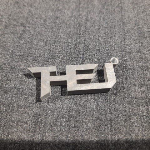
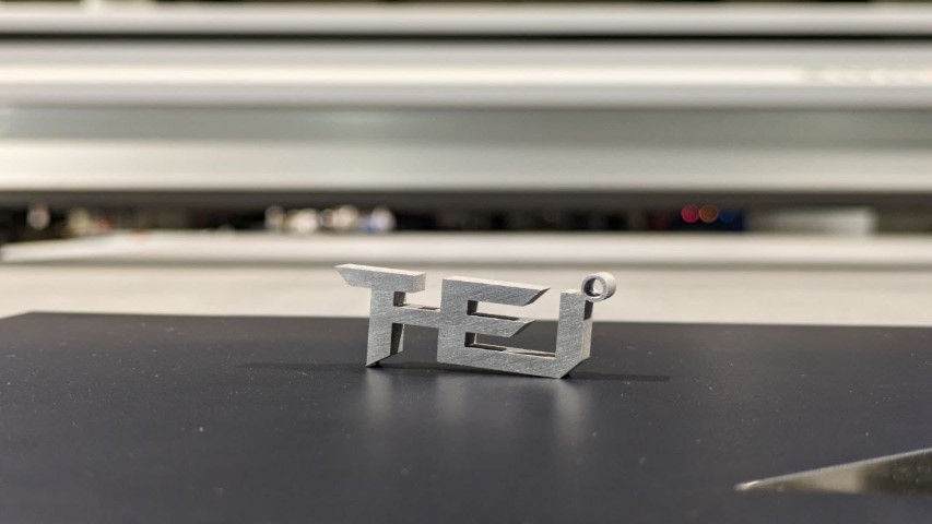
Result
After 13 minutes...
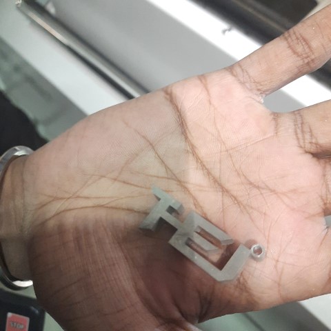
Sanding on water paper for smooth surface
Ta-da
Precision Checking
I checked all measurements using Vernier Calliper and here are the results:
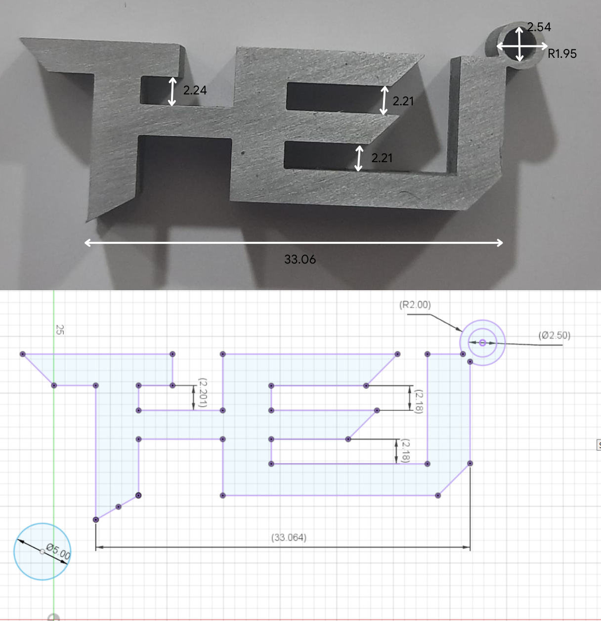
To conclude, I was able to obtain "value of tolerance" by using the EDM, and able to cut small details precisely.