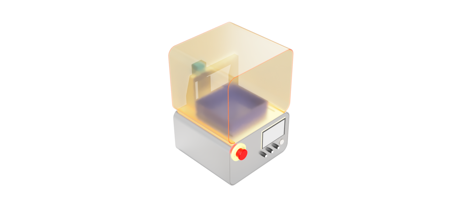

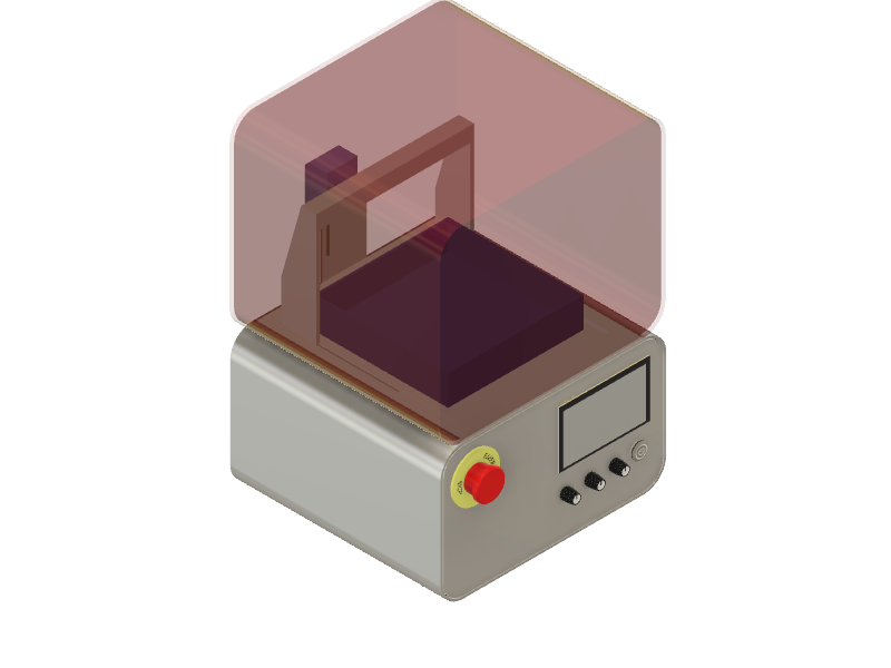
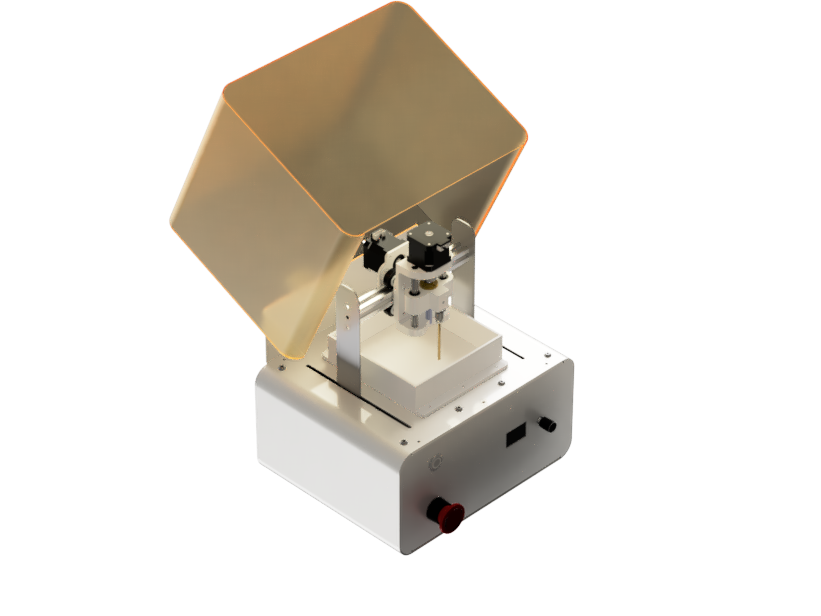
I am planning to build a mini desktop EDM. This was inspired by my days as an EDM operator in a small machine shop in Kerala. After that, I have always been intrigued that I needed a small machine that will help me cut metals and profile them. TADA, we have the mini EDM. The design was inspired by the Formlabs FORM 1 SLA 3D printer, and I really wanted to make it look the same.
Having started my journey as an EDM operator at the age of 18, I was immediately captivated by the precision and intricacy with which EDM could cut through metals. The process seemed almost magical, as it involved using electrical discharges to erode material, enabling the creation of highly detailed and accurate parts. This experience ignited my curiosity and passion for machining, leading me to envision a mini desktop EDM system that could bring the capabilities of this technology to a wider audience. Inspired by the sleek design of the Formlabs FORM 1 SLA 3D printer, I aim to infuse aesthetics with functionality, creating a visually appealing and user-friendly machine for metal cutting and profiling.
Week 1-2: Research and Requirements Gathering (2 weeks)
Week 3-4: Concept Development and Initial Design (2 weeks)
Week 5-6: Detailed Design and CAD Modeling (2 weeks)
Week 7-8: Simulation and Analysis (2 weeks)
Week 9-10: Material Sourcing and Prototyping (2 weeks)
Week 11-12: Assembly and Mechanical Integration (2 weeks)
Week 13: Electronics Design and Prototyping (1 week)
Week 13-14: Software Development and Interface Design (2 weeks)
Week 14-16: Testing, Optimization, and Documentation (3 weeks)
to i had some idea on the workings of an edm from a machinist perspective but i wanted to get more information on the power electronics part as i was having very little knowledge on it
so these are some of the reference that i was able to get
the most promising project that i was able to get was by a team called reck robotics and they have a dedicated power supply for a table top edm
.JPG) Reck robotics github
Reck robotics github
then i also came across a MTM project by mr.Will Langford it is a wire cut edm
fablab mtm wirecut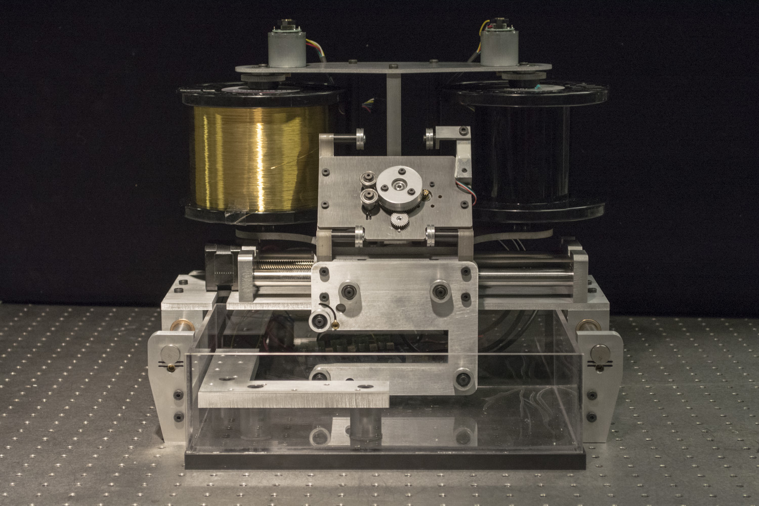
i also visited my workshop that i worked as a edm operator for checking their latest edm machines
i am yet to figure out the powersupply i am planning to conduct some testing based on few hypothesis i have
I finished the CAD design of the project
As I was approaching the build, due to some unforeseen circumstances, I had to take a three-week leave of absence from the academy. Now, I am left with one week to finish the project, so I have abandoned this project for the time being. However, I definitely plan to revisit it in the future.
When working with robots, safety is paramount to protect yourself and others. Follow these safety guidelines at all times:
By adhering to these safety guidelines, you can mitigate risks and ensure a safe and productive environment when working with your robot.
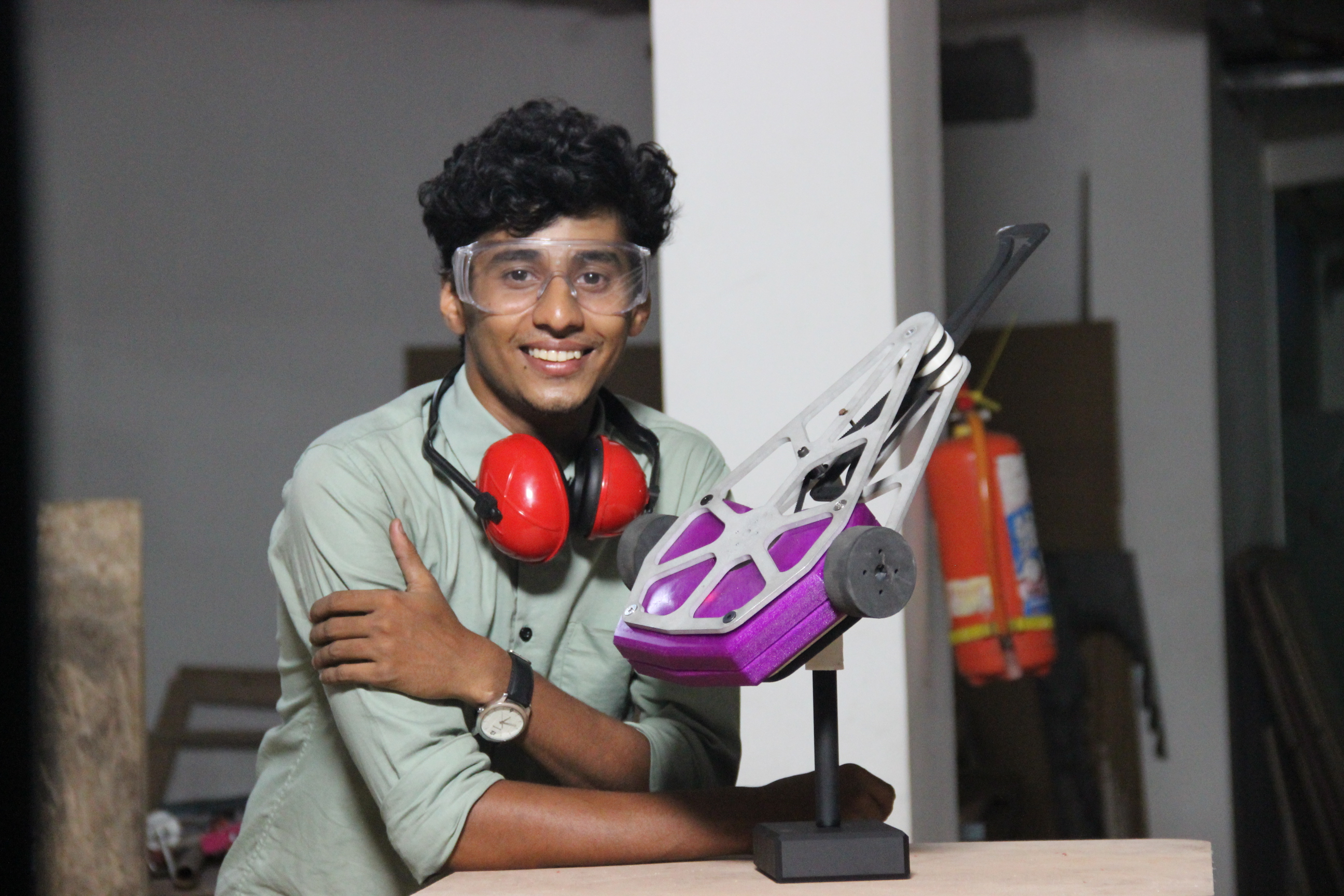
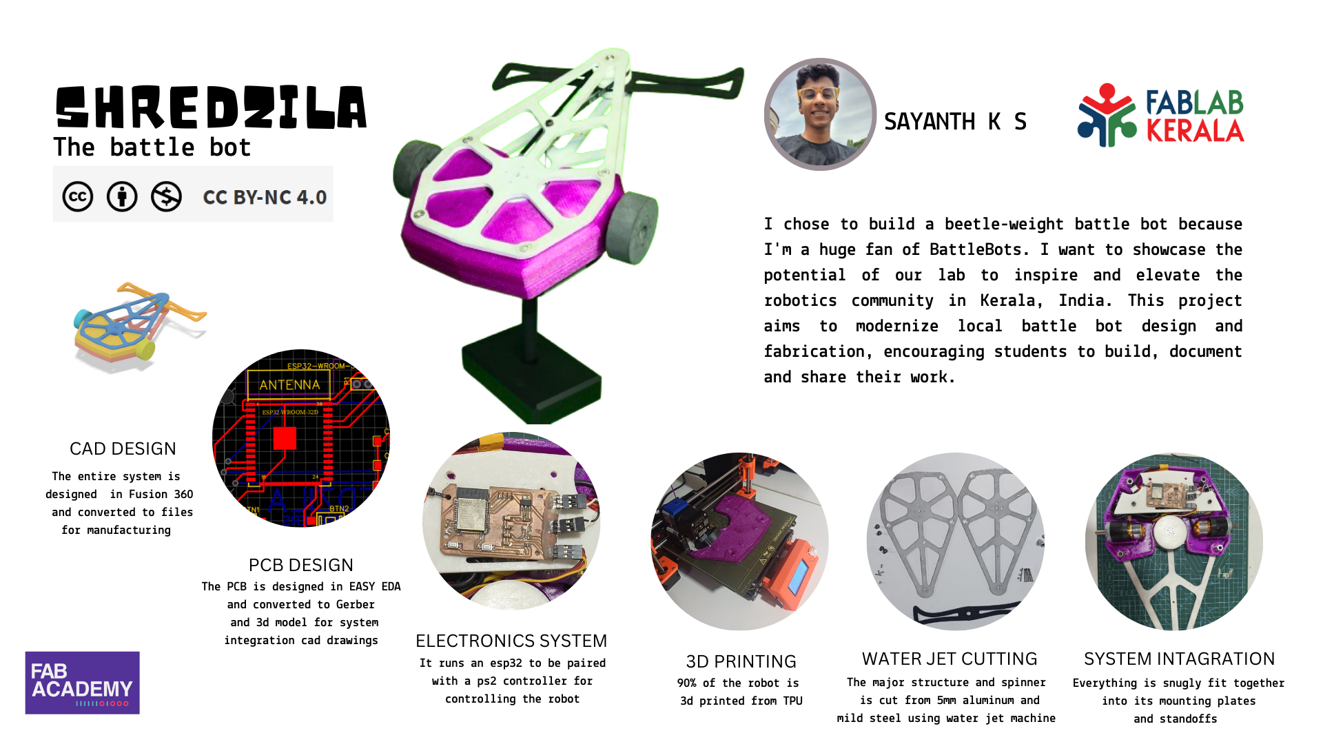
I have chosen to build a beetle weight battle bot as my project due to my passion for battle bots, especially my favorite bot, Tombstone. In our country, the concept of battle bots is still not widely recognized, and the robot design and fabrication techniques are quite rudimentary and outdated. As our lab is frequently visited by students, I aim to create a showcase robot that demonstrates the potential of our lab in constructing high-quality robots. This project will inspire students to build, document, and share their own work. Additionally, I hope to leverage the fab network to cultivate a top-class battle bots community in India, particularly in Kerala.
SHREDZILA is my beetle weight battle bot, weighing 3 pounds or less. It features a powerful horizontal spinner weapon, inspired by the famous Tombstone. Designed for agility and durability, SHREDZILA can deliver devastating blows in combat
SHREDZILA's design consists of three main components: the top-bottom structure, the weapon assembly, and the shell.
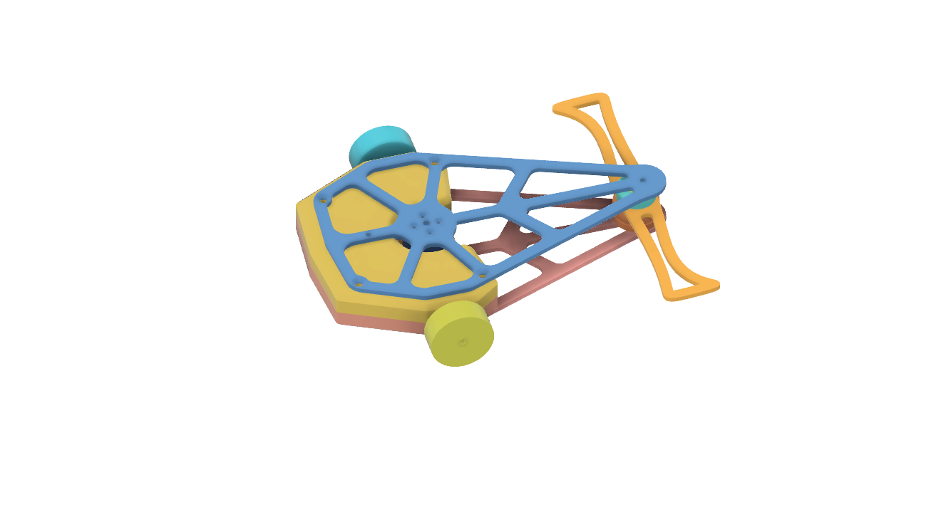
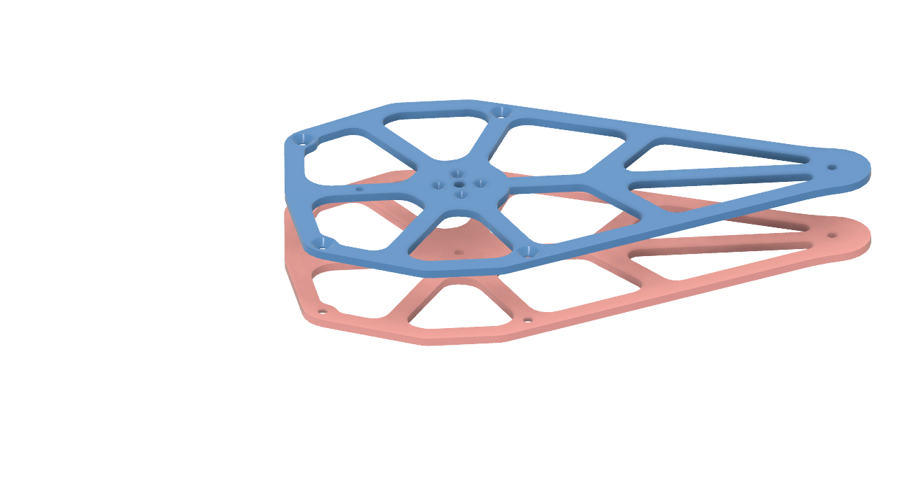
The top-bottom structure forms the backbone of SHREDZILA, providing support and stability. These components extend from the shell, ensuring structural integrity and balance during combat. Carefully engineered for durability and weight distribution, the top-bottom structure serves as the foundation for mounting the weapon assembly and other essential components. At the end of each segment of this structure, the weapon pulley and weapon are securely mounted, enabling precise control and powerful strikes.
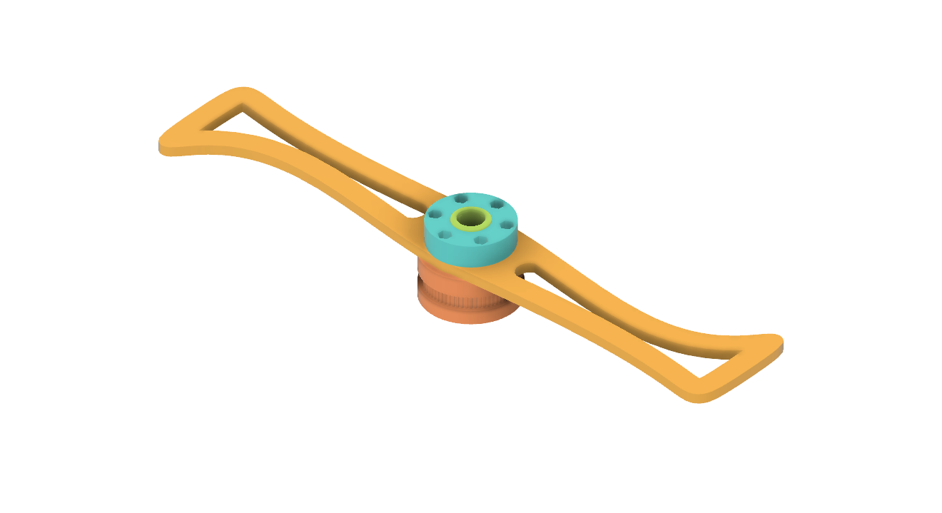
Positioned at the end of each top-bottom segment, the weapon assembly is the primary offensive component of SHREDZILA. Inspired by Tombstone, the horizontal spinner weapon is designed to deliver devastating blows to opponents. The weapon pulley, integrated into the top-bottom structure, provides rotational power to the weapon, enabling rapid spinning and maximum damage upon impact.
The shell encompasses SHREDZILA's top-bottom structure and serves as its outer armor. Designed for aerodynamics and durability, the shell provides protection against enemy attacks while enhancing the robot's overall aesthetics. Integrated seamlessly with the top-bottom structure, the shell contributes to SHREDZILA's sleek appearance while maintaining its resilience in combat.
you can see and download the cad file from here
SHREDZILA Fusion 360 fileyou can see and download the cad file from here
download the step file here| Item | Quantity | Description | Price (Estimate) | Source |
|---|---|---|---|---|
| Screws | ||||
| 6mm CSK Screws (12mm length) | 8 | Countersunk screws | fablab | |
| 3mm Screws (12mm length) | 4 | Standard screws | fablab | |
| 3mm Screws (40mm length) | 6 | Standard screws | fablab | |
| 3mm Lock Nuts | 6 | Locking nuts | fablab | |
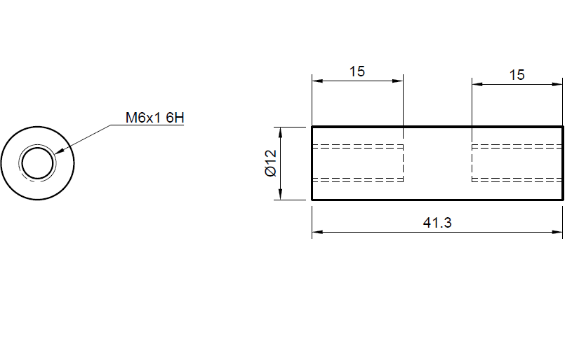
| 6mm Hex Standoff (12mm length) | 6 | Hexagonal standoffs | fablab | |
| 6mm Button Head Screws (15mm length) | 2 | Button head screws | fablab | |
| 3mm CSK Screws (12mm length) | 4 | Countersunk screws | fablab | |
| 3mm Screws (25mm length) | 2 | Standard screws | fablab | |
| Stock Materials | ||||
| 6063 Aluminum Plate (225mm x 365mm x 5mm) | 2 | Aluminum plate | fablab | |
| HCHCR Plate (375mm x 125mm x 5mm) | 1 | High carbon high chromium plate | ₹600 | Local hardware store |
| Additional Components | ||||
| TPU Filament (1kg) | 1 | Flexible filament for 3D printing | fablab | |
| Drawn Cup Needle Roller Bearing, HK1212 | 3 | Needle roller bearings | ₹150 | Local hardware store |
| Planetary Gear DC Motor 12V | 1 | 12V DC motor with planetary gears | ₹1200 | online marketplaces robu.in |
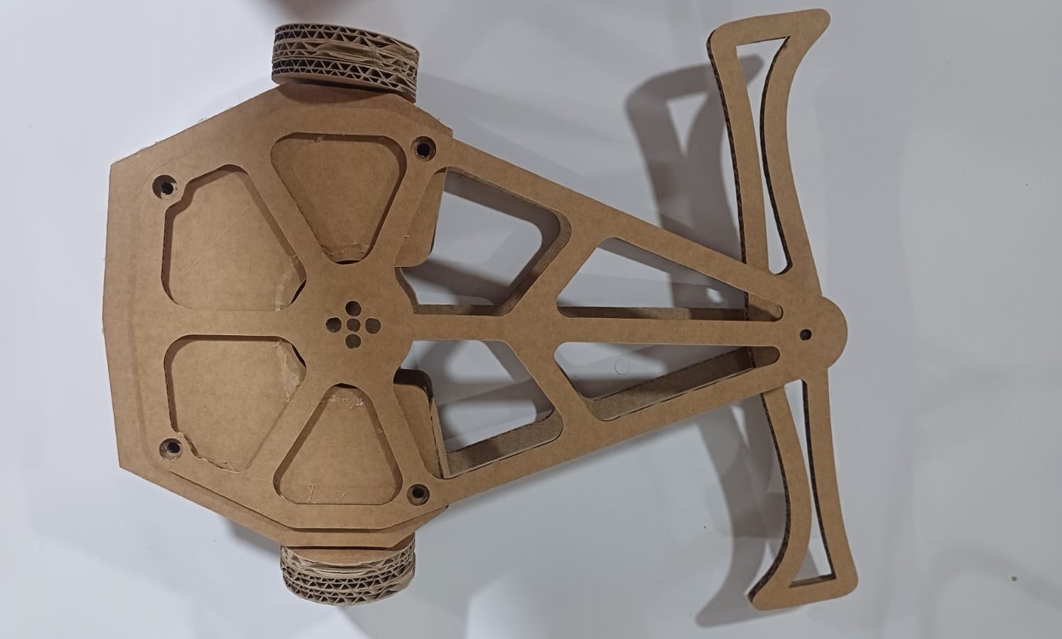
I successfully created a mock prototype of SHREDZILA using cardboard, leveraging the precision cutting capabilities of a Zund machine. This allowed me to translate my design from CAD software into tangible components with remarkable accuracy. By assembling these cardboard pieces, I gained valuable insights into the feasibility and functionality of my design, enabling me to iterate and refine before moving forward with more permanent materials. This iterative process not only saved time and resources but also ensured that the final product would meet my expectations and requirements.
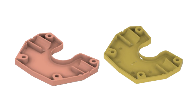
I 3D printed the shell of SHREDZILA using TPU filament to ensure flexibility and durability. TPU, being a flexible material, provides the necessary resilience to absorb impacts during battles while maintaining the integrity of the shell.
| Setting | Value |
|---|---|
| Layer Height | 0.2 mm |
| Print Speed | 30 mm/s |
| Extruder Temperature | 220°C |
| Bed Temperature | 60°C |
| Parameter | 6 |
| Infill | 40% |
| Infill Pattern | Grid |
| Retraction Distance | 1 mm |
| Retraction Speed | 20 mm/s |
| Cooling Fan | Off for the first few layers, then at 30% |
These settings were carefully chosen to balance strength and flexibility. The grid infill pattern at 40% density provides a robust internal structure, ensuring that the shell can withstand the rigors of combat without being too rigid. The parameter setting of 6 ensures adequate wall thickness, adding to the overall durability of the shell.
The combination of these settings and the TPU material resulted in a shell that is both tough and resilient, capable of protecting SHREDZILA's internal components while contributing to its sleek and aerodynamic design. This approach allowed me to create a high-quality, functional prototype ready for battle.
.jpeg)
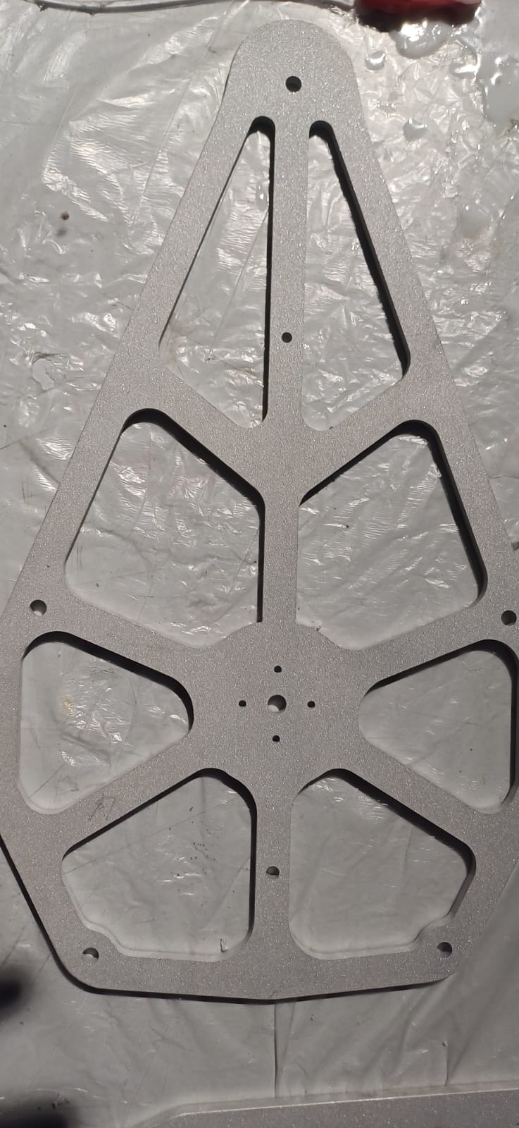
The weapon and top-bottom structure of SHREDZILA were manufactured using water jet cutting, a precise fabrication method that uses a high-pressure stream of water mixed with abrasive particles to cut through materials like aluminum. This process allows for intricate designs and precise cutting edges, ensuring that SHREDZILA's components are both strong and accurately shaped to meet the demands of competitive battle robot performance.
i used the protrak milling machine to mill a block as the showcase base i used a 100 *50 *15mm ms flat
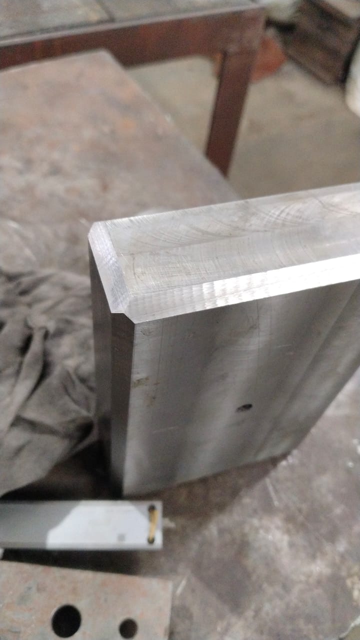
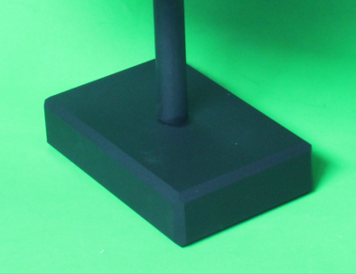
this the part that i milled out
you can reffer my moulding a casting week to know more on milling parts on protrak
i used the cnc lathe to make the all impotent bearing shaft for the robot , this part is the one that the weapon will spin on an di has to be presice that was the reson that i used the cnc lathe that was available on the lab
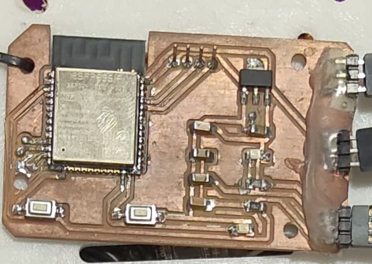
SHREDZILA's electronics are designed to ensure robust control and precise operation. The system is built around an ESP32 microcontroller, which is programmed via an FTDI breakout using the RX and TX pins. The ESP32 is chosen for its versatility and built-in Wi-Fi and Bluetooth capabilities, which facilitate wireless communication.
To control the robot's movement and weapon, three PWM pins from the ESP32 are utilized:
The printed circuit board (PCB) for SHREDZILA's electronics was designed using EasyEDA, an online EDA tool that simplifies the creation and management of complex electronic circuits. The PCB design was then milled using a Roland milling machine, which was operated through Fab Modules software. This process ensures precision and reliability in the PCB's construction.
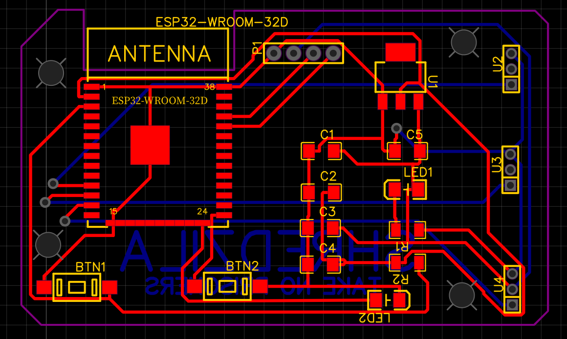
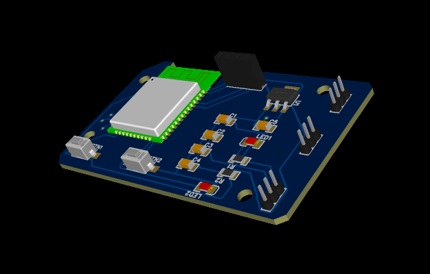
Once the PCB was milled, the electronic components were meticulously assembled onto the board. The assembly process included soldering various SMD components, ensuring solid connections and optimal performance. This thorough approach to the electronics setup is critical for SHREDZILA's operational effectiveness and durability in the demanding environment of robot combat.
| Item | Quantity | Description | Price (Estimate) | Source |
|---|---|---|---|---|
| Switch | 2 | Toggle Switch (SMD) | ₹5 | fablab |
| ESP32 Module | 1 | Microcontroller Development Board | ₹230 | fablab |
| Resistors (1208 package, as required) | Resistors for ESP32 Minimum Circuit | ₹2 | fablab | |
| 5v Voltage Regulator | 1 | LM7805 Voltage Regulator | ₹12 | fablab |
| Diode (1N4007) | 1 | Diode (1N4007) | ₹5 | fablab |
| Electrolytic Capacitor (100uF, 25V) | 1 | Electrolytic Capacitor (100uF, 25V) | ₹5 | fablab |
| Ceramic Capacitors (0.1uF) | 1 | Ceramic Capacitors (0.1uF) | ₹5 | fablab |
| Resistor (220 ohms) | 1 | Resistor (220 ohms) | ₹.50 | fablab |
| 3.3v Voltage Regulator | 1 | LM317 Voltage Regulator | ₹20 | fablab |
| Resistors (220 ohms, 1k ohm) | Resistors for LM317 Circuit | ₹.50 | fablab | |
| Electrolytic Capacitor (10uF, 25V) | 1 | Electrolytic Capacitor (10uF, 25V) | ₹5 | fablab |
| Ceramic Capacitors (0.1uF) | 1 | Ceramic Capacitors (0.1uF) | ₹3 | fablab |
| LED for Power Indicator | 1 | SMD LED (1208 package) | ₹1.5 | fablab |
| 20A ESC | 1 | Electronic Speed Controller (ESC) - 20A | ₹400 | fablab |
| 40A ESC | 1 | Electronic Speed Controller (ESC) - 40A | ₹1000 | fablab |
| 2212 BLDC Motor | 2 | Brushless DC Motor - 2212 | ₹450 | fablab |
| 3S LiPo Battery | 1 | Lithium Polymer Battery - 3S, 30C | ₹1800 | fablab |
| 3-Pin 2.54mm Male Berg Strip | 1 | 3-Pin Male Berg Strip (2.54mm pitch) | ₹5 | fablab |
| Terminal Connectors | 1 | Terminal Connectors (as required) | ₹5 | fablab |
By carefully designing and assembling the electronics, SHREDZILA achieves precise control and reliable performance, showcasing the capabilities of modern fabrication and electronic design techniques.
In my quest to incorporate a brushless drive into my project, I encountered a challenge: the lack of affordable planetary gear motors. To overcome this, I decided to create a custom solution using a 2212 BLDC motor. Here is the detailed process I followed:
Firstly, I extended the shaft of the 2212 BLDC motor to the opposite side, ensuring it could accommodate the planetary gear mechanism. I carefully removed the gear from a DC motor, which I planned to use with the BLDC motor. To ensure a secure fit, I used a file to create a flat portion on the BLDC motor's shaft. This flat surface was crucial for preventing any slippage once the gear was pressed onto the shaft.
Next, I pressed the gear onto the modified shaft of the BLDC motor, ensuring it was firmly attached. To complete the assembly, I designed and 3D printed an interconnecting part. This part served as a crucial link, connecting the planetary gear assembly to the BLDC motor securely and precisely.
This custom-built planetary gear drive provided the necessary performance required for my project, while also keeping the costs within a manageable range. By using readily available components and a bit of ingenuity, I was able to create a robust and efficient drive system tailored to my specific needs.
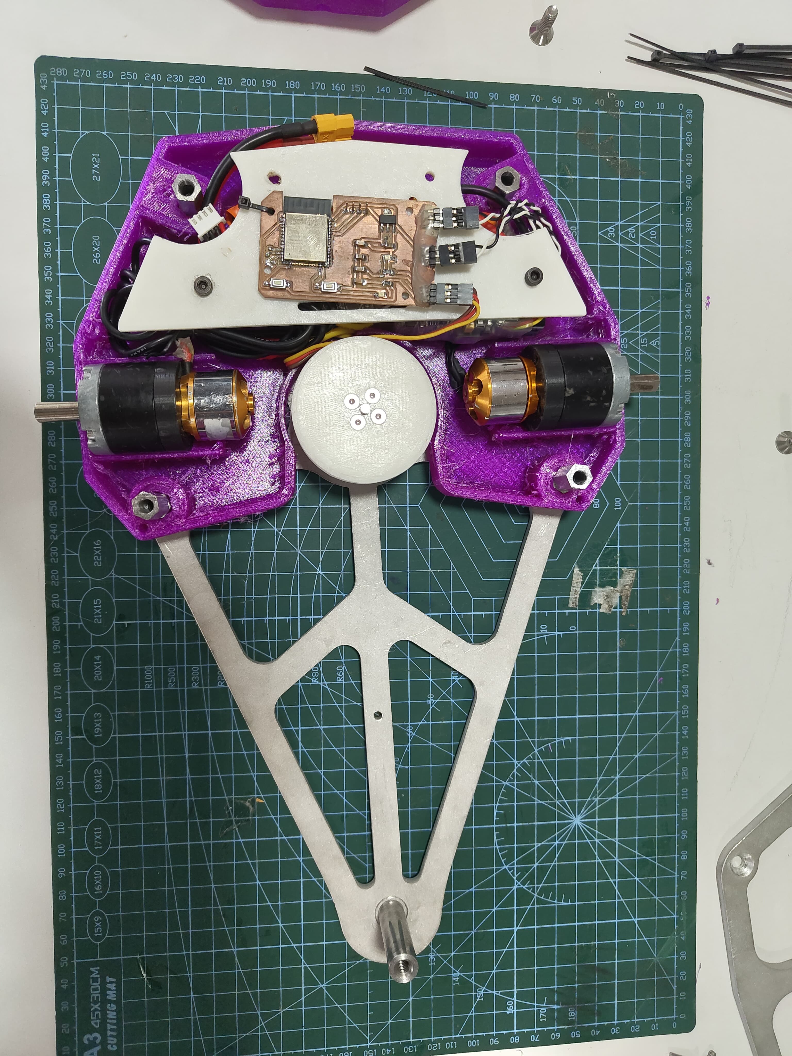
System integration at the assembly stage involves combining various components and subsystems into a cohesive unit. This process ensures that all parts work together harmoniously to achieve the desired functionality and performance of the final product. Key aspects of system integration at the assembly stage include:
This code is designed to control a robot using an ESP32 microcontroller and a PlayStation 3 (PS3) controller. The robot has three motors, each controlled by an Electronic Speed Controller (ESC). Below is a detailed explanation of the code:
#include <ESP32Servo.h>
#include <Ps3Controller.h>

#define ESC1_PIN 26
#define ESC2_PIN 27
#define ESC3_PIN 14  // Define pin for the third motor

Servo esc1;
Servo esc2;
Servo esc3;  // Define the third motor

void notify()
{
    int lx = Ps3.data.analog.stick.lx;
    int ly = Ps3.data.analog.stick.ly;

    // Forward speed based on vertical joystick movement
    int speed = map(ly, 0, 255, 1000, 2000);

    // Adjust ESC speeds for turning
    int esc1Speed = speed;
    int esc2Speed = speed;

    if (lx < 255) {  // Move left
        esc1Speed = map(lx, 0, 128, 1000, speed);
        esc2Speed = speed;
    } else if (lx > 255) {  // Move right
        esc1Speed = speed;
        esc2Speed = map(lx, 0, 255, speed, 1000);
    }

    // Set the ESC speeds
    esc1.writeMicroseconds(esc1Speed);
    esc2.writeMicroseconds(esc2Speed);

    // Control the third motor with the triangle button
    if (Ps3.data.button.triangle) {
        esc3.writeMicroseconds(2000);  // Full speed forward
    } else {
        esc3.writeMicroseconds(1000);  // Stop the motor
    }

    Serial.print("Left stick: x="); Serial.print(lx); Serial.print(" y="); Serial.println(ly);
    Serial.print("ESC1 speed: "); Serial.println(esc1Speed);
    Serial.print("ESC2 speed: "); Serial.println(esc2Speed);
    Serial.print("ESC3 speed: "); Serial.println(Ps3.data.button.triangle ? 2000 : 1000);
}

void onConnect(){
    Serial.println("Connected.");
}

void setup() {
    Serial.begin(115200);

    // Initialize ESCs
    esc1.attach(ESC1_PIN);
    esc2.attach(ESC2_PIN);
    esc3.attach(ESC3_PIN);  // Initialize the third motor

    // Set all ESCs to neutral (1000 microseconds)
    esc1.writeMicroseconds(1000);
    esc2.writeMicroseconds(10000);
    esc3.writeMicroseconds(1000);

    Ps3.attach(notify);
    Ps3.attachOnConnect(onConnect);
    Ps3.begin("");

    Serial.println("Ready.");
}

void loop() {
    if (!Ps3.isConnected())
        return;
}
This code is designed to control a robot using an ESP32 microcontroller and a PlayStation 3 (PS3) controller. The robot has three motors, each controlled by an Electronic Speed Controller (ESC). Below is a detailed explanation of the code:
#include <ESP32Servo.h>
#include <Ps3Controller.h>
Next, the pins for the ESCs are defined:
#define ESC1_PIN 26
#define ESC2_PIN 27
#define ESC3_PIN 14 // Define pin for the third motorThree servo objects are created to control the ESCs:
Servo esc1;
Servo esc2;
Servo esc3; // Define the third motorThe notify() function is used to handle the inputs from the PS3 controller. It reads the analog stick positions and adjusts the speeds of the motors accordingly:
void notify() {
    int lx = Ps3.data.analog.stick.lx;
    int ly = Ps3.data.analog.stick.ly;

    // Forward speed based on vertical joystick movement
    int speed = map(ly, 0, 255, 1000, 2000);

    // Adjust ESC speeds for turning
    int esc1Speed = speed;
    int esc2Speed = speed;

    if (lx < 255) {  // Move left
        esc1Speed = map(lx, 0, 128, 1000, speed);
        esc2Speed = speed;
    } else if (lx > 255) {  // Move right
        esc1Speed = speed;
        esc2Speed = map(lx, 0, 255, speed, 1000);
    }

    // Set the ESC speeds
    esc1.writeMicroseconds(esc1Speed);
    esc2.writeMicroseconds(esc2Speed);

    // Control the third motor with the triangle button
    if (Ps3.data.button.triangle) {
        esc3.writeMicroseconds(2000);  // Full speed forward
    } else {
        esc3.writeMicroseconds(1000);  // Stop the motor
    }

    Serial.print("Left stick: x="); Serial.print(lx); Serial.print(" y="); Serial.println(ly);
    Serial.print("ESC1 speed: "); Serial.println(esc1Speed);
    Serial.print("ESC2 speed: "); Serial.println(esc2Speed);
    Serial.print("ESC3 speed: "); Serial.println(Ps3.data.button.triangle ? 2000 : 1000);
}The onConnect() function is called when the PS3 controller successfully connects:
void onConnect(){
    Serial.println("Connected.");
}The setup() function initializes the serial communication, attaches the ESCs to their respective pins, and sets them to a neutral state. It also sets up the PS3 controller:
void setup() {
    Serial.begin(115200);

    // Initialize ESCs
    esc1.attach(ESC1_PIN);
    esc2.attach(ESC2_PIN);
    esc3.attach(ESC3_PIN);  // Initialize the third motor

    // Set all ESCs to neutral (1000 microseconds)
    esc1.writeMicroseconds(1000);
    esc2.writeMicroseconds(1000);
    esc3.writeMicroseconds(1000);

    Ps3.attach(notify);
    Ps3.attachOnConnect(onConnect);
    Ps3.begin("");

    Serial.println("Ready.");
}The loop() function continuously checks if the PS3 controller is connected. If it's not connected, it does nothing:
void loop() {
    if (!Ps3.isConnected())
        return;
}Before full assembly, individual components are tested to verify their functionality:
Once individual components are verified, they are integrated into the robot for system-wide testing:
With the robot fully assembled, functional tests are conducted to validate its performance:
Assembling the robot involves several steps, from preparing the mechanical components to integrating the electronics and ensuring everything works together smoothly. Below is a detailed description of the assembly process:
The first step is to assemble the mechanical components:
The robot uses custom-designed PCBs to control its electronic components:
Connecting the various electronic components is crucial for proper functionality:
The software setup involves programming the microcontroller and configuring the control systems:
The final steps involve assembling all components into the robot and performing rigorous testing:
The successful integration of mechanical, electronic, and software components ensures that the robot operates effectively in various combat situations, showcasing the capabilities of modern fabrication techniques and electronic control systems.
at last the project is finish this is my final project image and personation
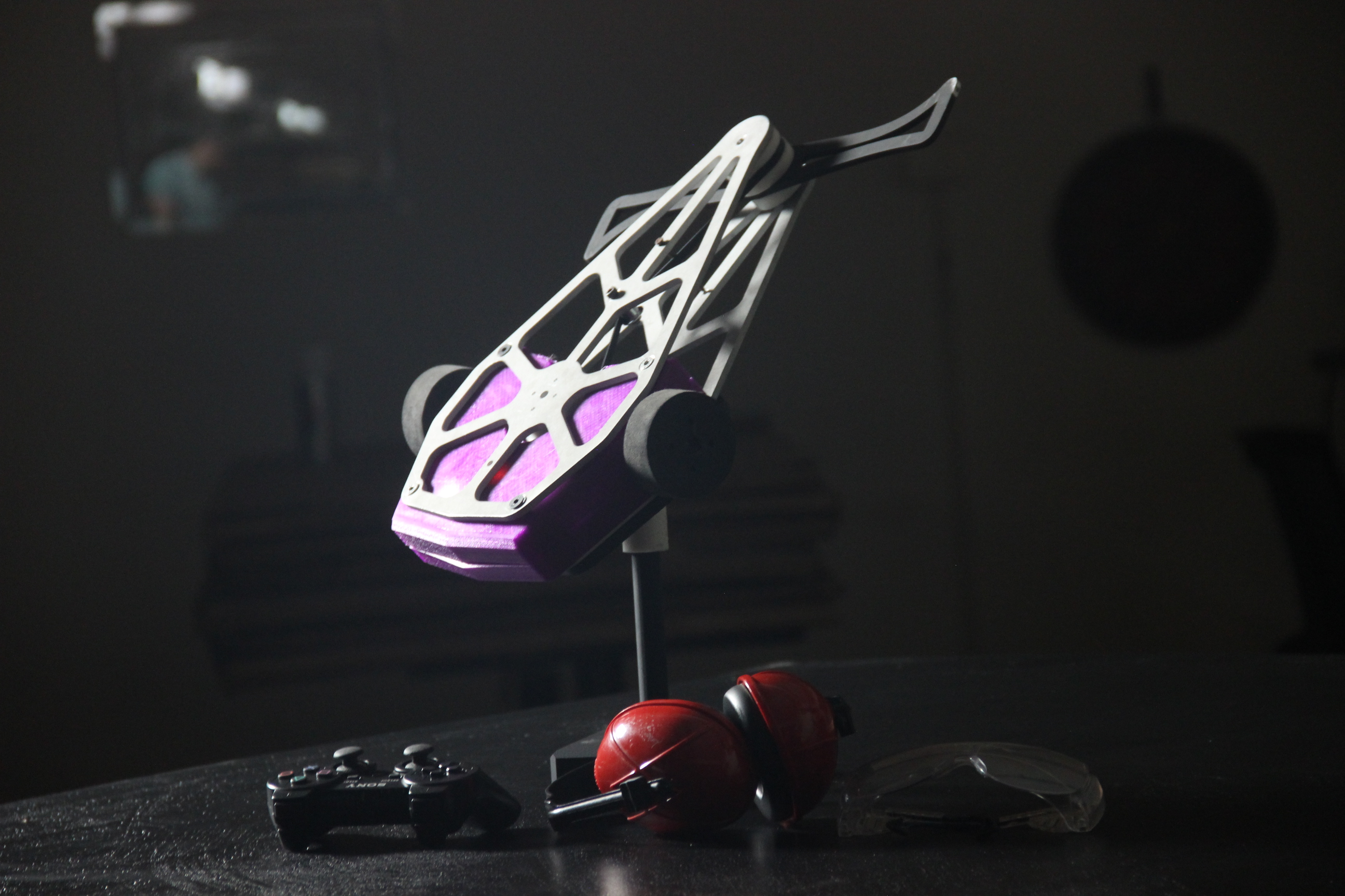
SHREDZILA
by SAYANTH K S is licensed under
CC BY-NC 4.0
![]()
![]()
![]()