This week is all about embbeded programming, i have bit of exerpince in workin g with emmbeded proggraming , i have build a lot of projects using arduino and esp this week will be really good as i was planning to get good insight towards embbeded proggarmeing
Embedded programming is the process of writing code specifically designed to run on embedded systems, which are small, specialized computers typically built into larger devices or systems. This programming involves optimizing code to efficiently utilize limited resources such as memory, processing power, and energy consumption. Embedded systems are found in a wide range of devices including smartphones, household appliances, medical devices, automotive systems, and industrial machinery.
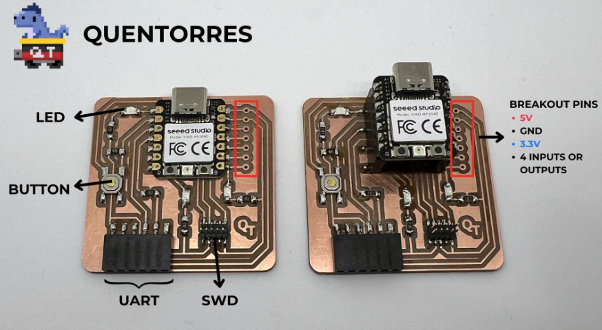
"Quentorres" is a development board initially conceived by Quentin Bolsée and further refined by Adrián Torres. It is designed to serve as an inclusive tool for programming education and development. The board aims to provide a perfect balance between advanced capabilities suitable for experienced programmers and a beginner-friendly interface tailored for those learning to code.
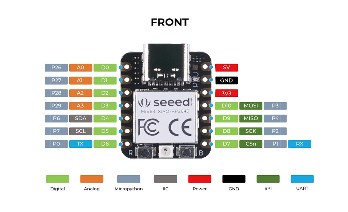
The Xiao RP2040 is a compact microcontroller board developed by Seeed Studio, leveraging the power of the RP2040 chip from the Raspberry Pi Foundation. Designed to offer a balance of performance, versatility, and ease of use, the Xiao RP2040 is ideal for a wide range of applications, from simple DIY projects to more complex embedded systems.
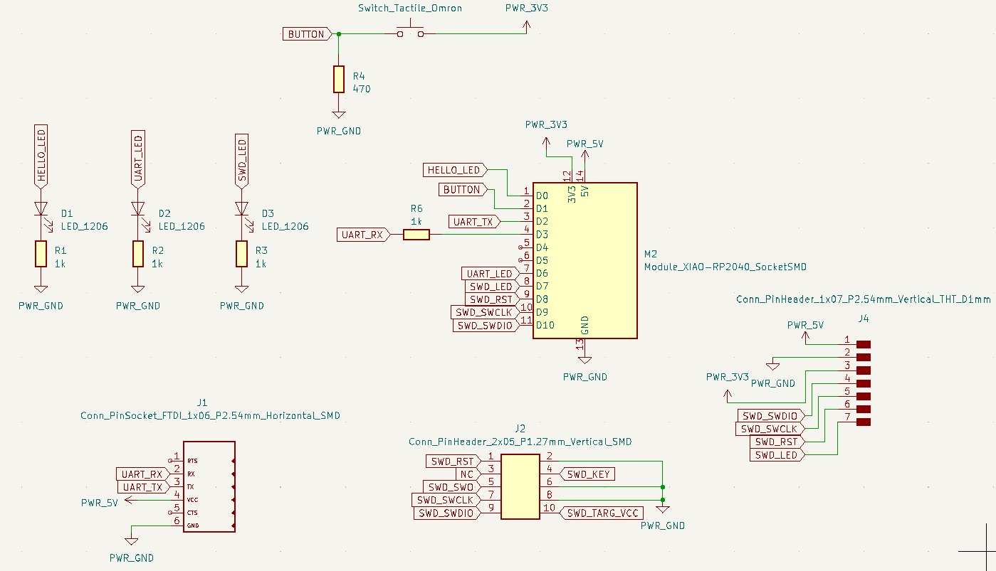
| Pin | Connection |
|---|---|
| 3V3 | PWR_3V3 |
| GND | PWR_GND |
| 5V | 5V |
| D0 | HELLO_LED |
| D1 | BUTTON |
| D7 | SWD_LED |
| D6 | UART_LED |
| D10 | GPIO |
| D9 | GPIO |
| D8 | GPIO |
| D7 | GPIO |
As I have done this already in week 4, I just loaded the example program and connected the board via USB, selected the port and board type, and uploaded the code. The expected output was observed.
      #define LED_PIN 25 // This pin may vary depending on the specific board configuration

      void setup() {
        // Initialize the LED pin as an output
        pinMode(LED_PIN, OUTPUT);
      }

      void loop() {
        // Turn the LED on (HIGH) for 1 second
        digitalWrite(LED_PIN, HIGH);
        delay(1000);

        // Turn the LED off (LOW) for 1 second
        digitalWrite(LED_PIN, LOW);
        delay(1000);
      }
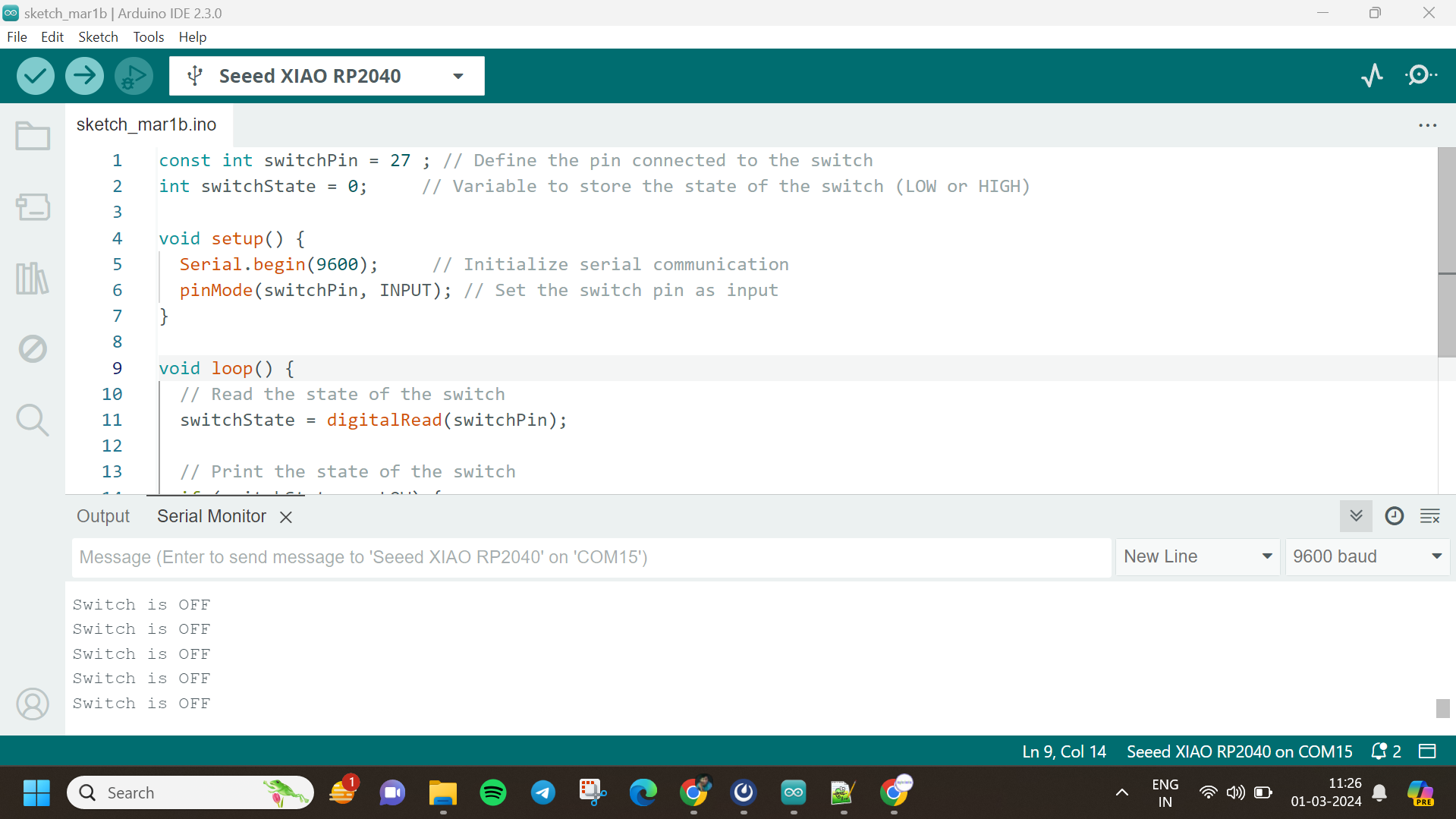
This project outlines the process of utilizing the Seeed Studio XIAO RP2040, a compact development board powered by the RP2040 microcontroller, to read the state of a switch. By connecting one terminal of the switch to a digital input pin on the XIAO RP2040 and the other to ground, the microcontroller can detect whether the switch is "ON" or "OFF". The code, tailored for the XIAO RP2040, continuously monitors the state of the input pin and communicates the switch status.
i used the following code
        const int switchPin = 27; // Define the pin connected to the switch
        int switchState = HIGH;  // Initial state of the switch is "off"
        int previousSwitchState = HIGH; // Variable to store the previous state of the switch

        void setup() {
          Serial.begin(9600);     // Initialize serial communication
          pinMode(switchPin, INPUT_PULLUP); // Set the switch pin as input with internal pull-up resistor
        }

        void loop() {
          // Read the state of the switch
          switchState = digitalRead(switchPin);

          // Check if the switch state has changed
          if (switchState != previousSwitchState) {
            // Check if the switch is pressed
            if (switchState == LOW) {
              // Toggle the switch state
              if (previousSwitchState == HIGH) {
                Serial.println("Switch is ON");
              } else {
                Serial.println("Switch is OFF");
              }
            }

            // Update the previous switch state
            previousSwitchState = switchState;
          }
        }
For this project, I set out to control an LED using a switch with the Seeed Studio XIAO RP2040 microcontroller board. Initially, I wired the switch to one of the XIAO's digital input pins (pin 27) and the LED to one of its digital output pins (pin 26). In the code, I first defined these pins and set pin 27 as the input for the switch and pin 26 as the output for the LED within the setup() function. Then, in the loop() function, I continuously monitored the state of the switch using digitalRead(switchPin), storing its state in a variable switchState. If the switch is pressed (reading LOW), the LED turns on via digitalWrite(ledPin, HIGH). Conversely, if the switch is not pressed (reading HIGH), the LED turns off via digitalWrite(ledPin, LOW). This simple program allows for the direct control of the LED based on the state of the switch, facilitating basic interaction and demonstrating the fundamental principles of input and output interfacing with a microcontroller.
        // constants won't change. They're used here to set pin numbers:
        const int buttonPin = 27;  // the number of the pushbutton pin
        const int ledPin = 26;    // the number of the LED pin

        // variables will change:
        int buttonState = 0;        // variable for reading the pushbutton status
        int lastButtonState = LOW;  // variable to store the previous button state
        int ledState = LOW;         // variable to store the current LED state
        bool buttonPressedFlag = false; // flag to indicate if button is pressed

        void setup() {
          // initialize the LED pin as an output:
          pinMode(ledPin, OUTPUT);
          // initialize the pushbutton pin as an input:
          pinMode(buttonPin, INPUT);
        }

        void loop() {
          // read the state of the pushbutton value:
          buttonState = digitalRead(buttonPin);

          // check if the button is pressed and the previous state was not pressed:
          if (buttonState == HIGH && lastButtonState == LOW && !buttonPressedFlag) {
            // set button pressed flag to true
            buttonPressedFlag = true;
            // toggle LED state:
            ledState = !ledState;
            // update LED accordingly:
            digitalWrite(ledPin, ledState);
          }

          // check if the button is released and the previous state was pressed:
          if (buttonState == LOW && lastButtonState == HIGH) {
            // reset button pressed flag
            buttonPressedFlag = false;
          }

          // save the current state as the last state, for next time through the loop:
          lastButtonState = buttonState;
        }
Debouncing refers to the phenomenon where a mechanical switch or button, when pressed or released, can produce multiple rapid transitions between ON and OFF states due to physical bouncing of the switch contacts. This bouncing can result in erratic behavior or multiple false readings, which may cause issues in electronic circuits, especially when using switches for digital input. Debouncing is the process of filtering out these rapid transitions to ensure a stable and reliable signal. This is typically achieved by adding a small delay or using software algorithms to ignore rapid state changes and only register a stable, consistent state of the switch. Debouncing ensures accurate and consistent readings from switches, preventing unintended triggering of actions in electronic systems.
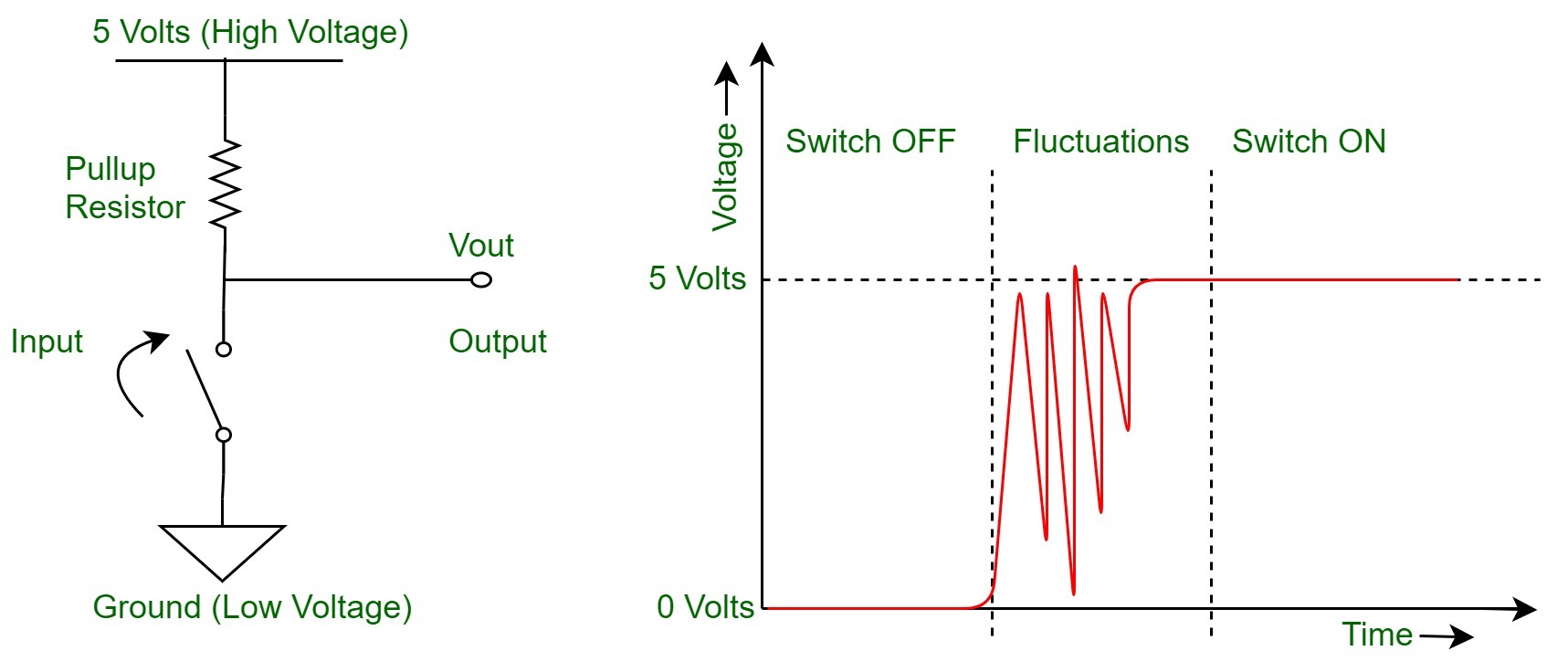
In the program, debouncing is implemented implicitly through the delay function delay(100) placed at the end of the loop() function. This delay introduces a brief pause of 100 milliseconds after reading the state of the switch and before looping back to check the switch state again. During this delay, any potential bouncing of the switch contacts is effectively ignored, allowing for a stable and reliable reading of the switch state. This simple debouncing technique helps ensure that the program reacts appropriately to deliberate changes in the switch state while filtering out any rapid, unintended fluctuations caused by mechanical bouncing.
 const int buttonPin = 27;
const int ledPin = 26;

void setup() {
  pinMode(ledPin, OUTPUT);
  pinMode(buttonPin, INPUT);
}

void loop() {
  int buttonState = digitalRead(buttonPin);

  if (buttonState == HIGH) {
    digitalWrite(ledPin, !digitalRead(ledPin));
    while(digitalRead(buttonPin) == HIGH); // Wait for button release
    delay(100); // Debounce delay
  }
}
In the updated program, debouncing is achieved using flags to detect and ignore rapid state changes of the switch. Two flags, switchState and lastSwitchState, are introduced to track the current and previous states of the switch, respectively. Initially, both flags are set to HIGH (or 1) to indicate that the switch is in the released state. Within the loop() function, the program first checks if the current state of the switch (switchState) is different from the previous state (lastSwitchState). If they are different, it means there has been a change in the switch state. To further ensure stability, a delay of 50 milliseconds (delay(50)) is introduced after reading the switch state to allow for debounce. During this delay, any bouncing of the switch is effectively ignored. After the delay, the program updates the lastSwitchState to match the current state (switchState), ensuring that it reflects the most recent stable state of the switch. This method of debouncing using flags helps prevent false triggers caused by switch bouncing, providing a more reliable and accurate reading of the switch state.
            const int switchPin = 27;   // Pin connected to the switch
            const int ledPin = 26;      // Pin connected to the LED
            int switchState = HIGH;     // Current state of the switch
            int lastSwitchState = HIGH; // Previous state of the switch

            void setup() {
              pinMode(switchPin, INPUT); // Set switch pin as input
              pinMode(ledPin, OUTPUT);   // Set LED pin as output
            }

            void loop() {
              switchState = digitalRead(switchPin); // Read the state of the switch

              // Check for a change in switch state
              if (switchState != lastSwitchState) {
                // Debounce by introducing a delay
                delay(50);
                // Update last switch state to match current state
                lastSwitchState = switchState;

                // If switch is pressed (LOW), turn on the LED
                if (switchState == LOW) {
                  digitalWrite(ledPin, HIGH);
                } else {
                  digitalWrite(ledPin, LOW); // Otherwise, turn off the LED
                }
              }
            }
This code controls a sequence of three LEDs using a pushbutton switch with a XIAO RP2040 microcontroller. Upon pressing the switch, the code cycles through the LEDs one by one, illuminating each LED in turn. The pushbutton's state is continuously monitored, and when it is detected as pressed while in the unpressed state, the code advances to the next LED in the sequence. To ensure smooth operation, a flag is used to prevent multiple LED changes with a single press. When the button is released, the flag is reset, allowing for the detection of subsequent presses. This program demonstrates a simple yet effective way to create interactive LED patterns with user input.
        // constants won't change. They're used here to set pin numbers:
        const int buttonPin = 27;   // the number of the pushbutton pin
        const int ledPins[] = {26, 0, 1}; // an array to hold the LED pin numbers
        const int numLeds = 3;      // number of LEDs
        int currentLed = 0;         // variable to keep track of the current LED
        int buttonState = 0;        // variable for reading the pushbutton status
        int lastButtonState = LOW;  // variable to store the previous button state
        bool buttonPressedFlag = false; // flag to indicate if button is pressed

        void setup() {
          // initialize the LED pins as outputs:
          for (int i = 0; i < numLeds; ++i) {
            pinMode(ledPins[i], OUTPUT);
          }
          // initialize the pushbutton pin as an input:
          pinMode(buttonPin, INPUT);
        }

        void loop() {
          // read the state of the pushbutton value:
          buttonState = digitalRead(buttonPin);

          // check if the button is pressed and the previous state was not pressed:
          if (buttonState == HIGH && lastButtonState == LOW && !buttonPressedFlag) {
            // set button pressed flag to true
            buttonPressedFlag = true;

            // Turn off the previously lit LED
            digitalWrite(ledPins[currentLed], LOW);

            // Move to the next LED
            currentLed = (currentLed + 1) % numLeds;

            // Toggle the state of the current LED
            digitalWrite(ledPins[currentLed], HIGH);
          }

          // check if the button is released and the previous state was pressed:
          if (buttonState == LOW && lastButtonState == HIGH) {
            // reset button pressed flag
            buttonPressedFlag = false;
          }

          // save the current state as the last state, for next time through the loop:
          lastButtonState = buttonState;
        }
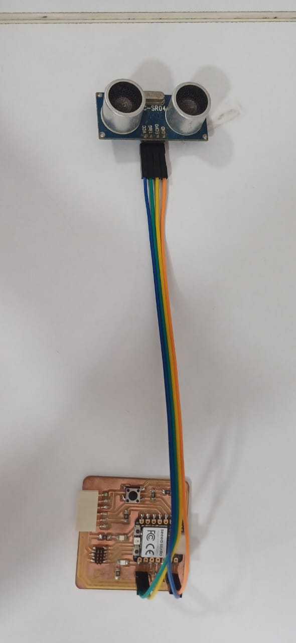
experimented with an ultrasonic sensor without relying on any external libraries with my Quentorres board. First, I connected the ultrasonic sensor to the board, ensuring the trigger and echo pins were appropriately linked to GPIO pins. Then, I delved into writing the code. Within the setup function, I defined the pins accordingly, setting the trigger pin as an output and the echo pin as an input. To measure distance, I employed a straightforward technique: sending a brief pulse to the trigger pin and timing the echo pin's transition from LOW to HIGH and back to LOW. This timing correlates directly with the distance detected by the sensor. Using this data and the speed of sound, I calculated the distance. After uploading the code to my Quentorres board and opening the serial monitor, I could observe real-time distance measurements displayed in centimeters. Adjustments were made as necessary to ensure accuracy, considering factors such as sensor specifications and environmental conditions. Overall, the process provided a hands-on understanding of ultrasonic sensor operation and data interpretation without relying on pre-existing libraries, enhancing my comprehension of microcontroller interfacing and sensor integration.
    const int trigPin = 4;
const int echoPin = 3;
// defines variables
long duration;
int distance;
void setup() {
  pinMode(trigPin, OUTPUT); // Sets the trigPin as an Output
  pinMode(echoPin, INPUT); // Sets the echoPin as an Input
  Serial.begin(9600); // Starts the serial communication
}
void loop() {
  // Clears the trigPin
  digitalWrite(trigPin, LOW);
  delayMicroseconds(2);
  // Sets the trigPin on HIGH state for 10 micro seconds
  digitalWrite(trigPin, HIGH);
  delayMicroseconds(10);
  digitalWrite(trigPin, LOW);
  // Reads the echoPin, returns the sound wave travel time in microseconds
  duration = pulseIn(echoPin, HIGH);
  // Calculating the distance
  distance = duration * 0.034 / 2;
  // Prints the distance on the Serial Monitor
  Serial.print("Distance: ");
  Serial.println(distance);
  delay(1000);
}
Utilizing a library for the ultrasonic sensor simplifies the process by abstracting away low-level details, allowing for easier interfacing. Here's how I approached it: I recently decided to experiment with an ultrasonic sensor using my Quentorres board, this time opting to utilize a library for smoother integration. Initially, I connected the ultrasonic sensor to the appropriate GPIO pins on the board, ensuring a secure connection. Next, I focused on the coding aspect. With the library at hand, I began by including it in my Arduino sketch, making the necessary preparations for interfacing with the sensor. This involved defining the trigger and echo pins, setting them up within the setup function, and initializing the ultrasonic sensor object with these pin configurations. Once the groundwork was laid, I moved on to the main loop of the program. Here, I simply invoked the library's function to obtain distance measurements. This function handled the intricacies of sending trigger signals, measuring echo pulses, and calculating distances based on the time taken for the signal to bounce back. After uploading the code to my Quentorres board, I eagerly observed the serial monitor for real-time distance readings. Thanks to the library's abstraction, I could effortlessly interpret the distance data without delving into the nitty-gritty details of signal timings and calculations.
        #include NewPing.h

          #define TRIGGER_PIN 4
          #define ECHO_PIN 3
          #define MAX_DISTANCE 200 // Maximum distance to measure in centimeters

          NewPing sonar(TRIGGER_PIN, ECHO_PIN, MAX_DISTANCE);

          void setup() {
            Serial.begin(9600);
          }

          void loop() {
            delay(50); // Wait between measurements

            unsigned int distance = sonar.ping_cm(); // Get distance in centimeters

            if (distance == 0) {
              Serial.println("Out of range");
            } else {
              Serial.print("Distance: ");
              Serial.print(distance);
              Serial.println(" cm");
            }
          }
Embarking on the thrilling journey of MicroPython exploration with the Seeed Studio XIAO RP2040 necessitates meticulous attention to both software setup and hardware interaction. To commence this journey, the foundational step involves configuring the software environment to seamlessly communicate with the XIAO RP2040 board. This entails the installation of Thonny Editor, meticulously chosen to match your operating system, ensuring a harmonious integration of the development environment with your chosen platform. Subsequently, configuring Thonny settings to align with the specificities of the XIAO RP2040 board ensures smooth communication and paves the way for effortless code deployment.
Transitioning from software configuration to tangible hardware interaction, the journey unfolds with the illumination of the onboard LED. This preliminary exercise not only serves as a litmus test for the functionality of the XIAO RP2040 board but also acquaints users with the fundamentals of MicroPython coding practices. Through the deployment of a simple script orchestrating the LED's luminosity, users gain firsthand experience in crafting and executing code snippets, laying the groundwork for more intricate projects to come.
from machine import Pin, Timer

led = Pin(25, Pin.OUT)
Counter = 0
Fun_Num = 0

def fun(tim):
    global Counter
    Counter = Counter + 1
    print(Counter)
    led.value(Counter%2)

tim = Timer(-1)
tim.init(period=1000, mode=Timer.PERIODIC, callback=fun)
Venturing further into the realm of hardware manipulation, the integration of third-party libraries unlocks a realm of possibilities, amplifying the XIAO RP2040's potential. With the acquisition and integration of the ws2812.py library, users are bestowed with the ability to wield the RGB LED adorning the XIAO RP2040, painting vibrant hues across the spectrum and breathing life into their creations. This expansion beyond basic LED control not only showcases the adaptability and versatility of MicroPython but also empowers users to unleash their creativity in crafting visually captivating embedded projects.
from machine import Pin, Timer

led = Pin(25, Pin.OUT)
Counter = 0
Fun_Num = 0

def fun(tim):
    global Counter
    Counter = Counter + 1
    print(Counter)
    led.value(Counter%2)

tim = Timer(-1)
tim.init(period=1000, mode=Timer.PERIODIC, callback=fun)
I used the following wiki for doing the MicroPython
Seeed Studio XIAO RP2040 with MicroPython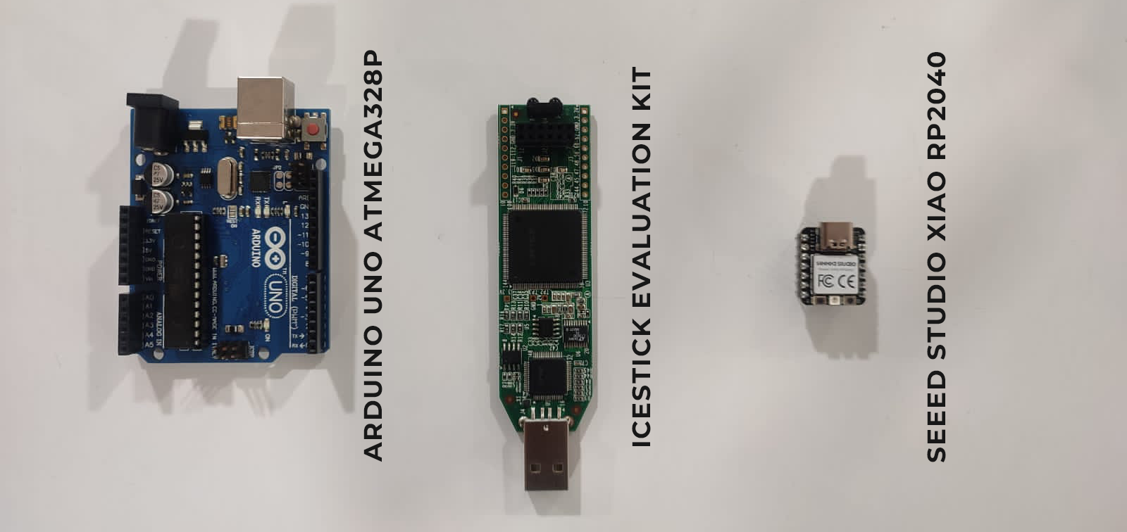 group assingment