Week 12 Assignment
MOULDING AND CASTING
What an exiting week this is, as i am a tool and die maker by proffesion this week is really interesting for me
Group Assignment Week 12
 Group Assignment
SAFETY FIRST
Safety was the top priority as I rolled into this week, especially with milling, silicon, and resin casting on the agenda. With these processes, ensuring a safe working environment is crucial to protect both personnel and equipment. From wearing appropriate personal protective equipment (PPE) to following established safety protocols, every step was taken to minimize risks. When dealing with milling, attention was given to tool handling and machine operation to prevent accidents. For silicon and resin casting, proper ventilation and handling procedures were implemented to avoid exposure to harmful fumes and chemicals. By prioritizing safety, we aimed to create a workspace where everyone could focus on their tasks with peace of mind, knowing that their well-being was safeguarded.
STARTING WITH A DESIGN
so as this week i planned to make a small surf board as i really like surfing and skim boarding, and it will look a cool desktop toy
ASSESABLITY CHECK
I conducted a thorough accessibility check to ensure that the components are easily machinable, specifically focusing on tool accessibility. Using advanced CAD software and physical prototypes, I meticulously examined the design to guarantee that machining operations could be performed efficiently.
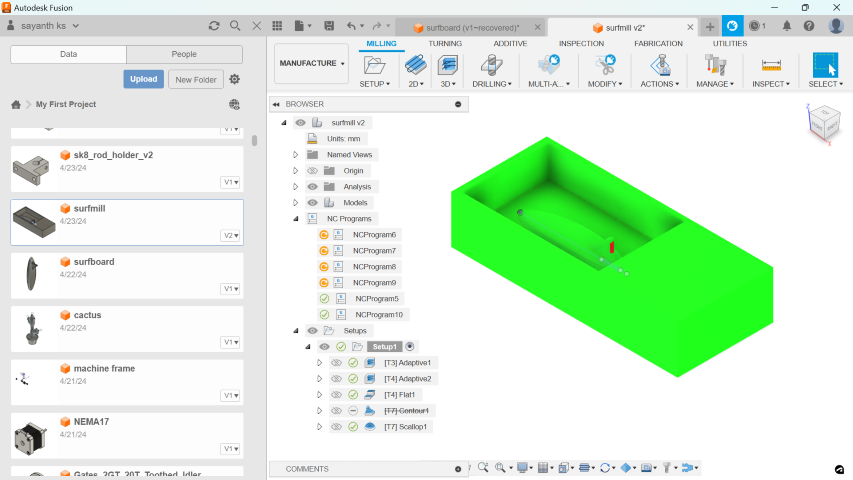
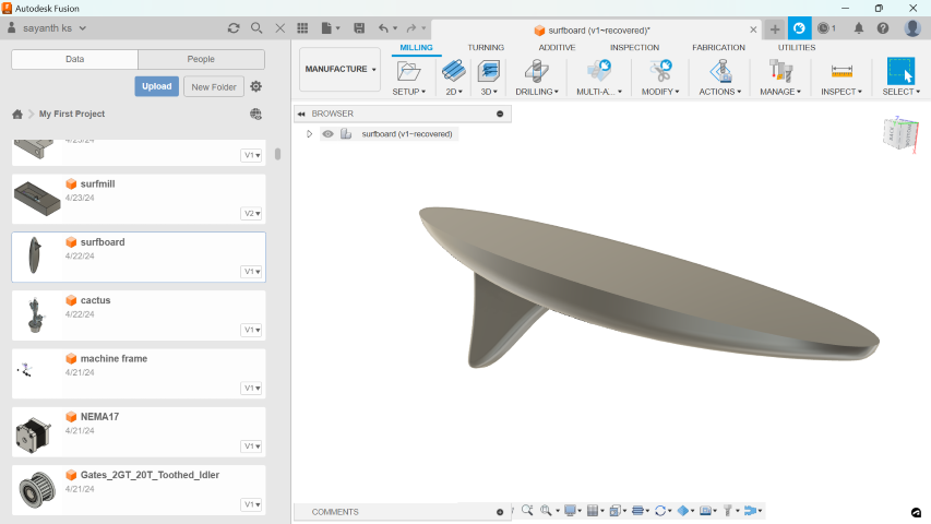
CAM
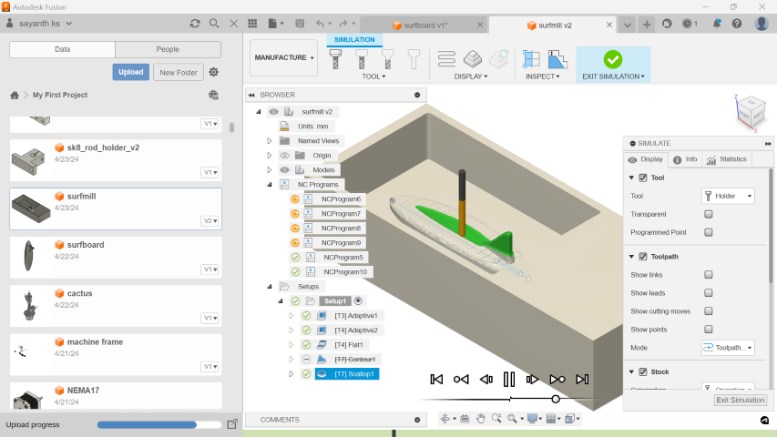
Utilizing Fusion 360's CAM capabilities, I'm preparing my surfboard design for manufacturing on a DPM RX 2 Vertical Milling Machine using machining wax blocks.
In Fusion 360, the CAM workspace facilitates milling operations, allowing users to select cutting tools, configure material properties, and set machining parameters. Within this environment, users generate and adjust toolpaths to direct the cutting tool's movements. Additionally, Fusion 360 offers simulation features to verify the accuracy of toolpaths and ensure alignment with desired specifications. Once finalized and validated, the toolpaths are exported as G-code, a programming language for CNC machines, guiding the milling machine to produce the desired part.
CAM Setup
- Navigate to the Manufacturing workspace by selecting Manufacturing Environment from the Machining dropdown menu.
- Configure the machining interface by selecting Setup > New Setup. Establish the stock and axes, setting the Work Coordinate Systems (WCS) offset to 1.
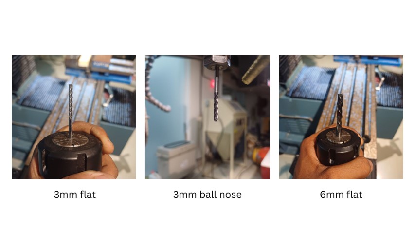
Tool Selection
- Access the Manage > Tool Library to add necessary tools to the library, including those from the FabLab.
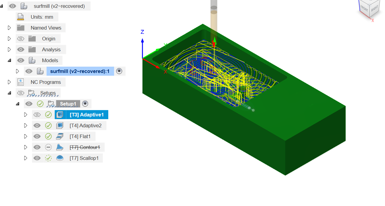
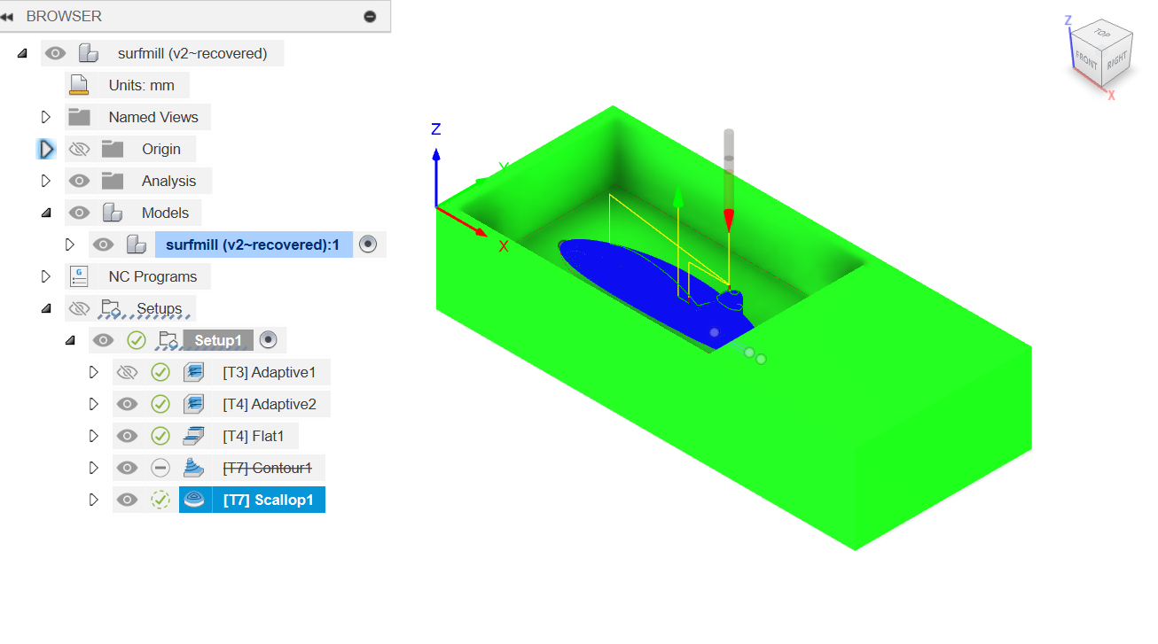
Operations
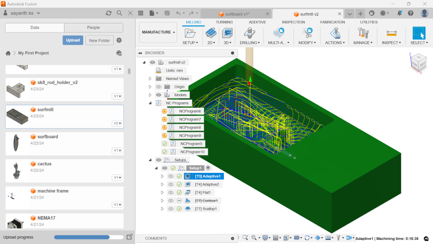
- Adaptive Clearing 1:
- Mill Bit: 6mm Flat End Mill 2 Flutes
- Adaptive Clearing 2:
- Mill Bit: 3mm Flat End Mill 4 Flutes
- Flat:
- Mill Bit: 3mm Flat End Mill 4 Flutes
- Scallop:
- Mill Bit: 3mm Ball Nose Mill 4 Flutes

Additional Settings
- Spindle Speed: 4000 rpm
- Cutting Feedrate: 900 mm/min
- Retraction Policy: Minimum Retraction
- Ramping Angle: 20 deg
Simulation
After setting each operation, simulate by right-clicking on the operation.
Post Processing
- Right-click on the job and select "Post Process."
- Specify the G-code's save location, select appropriate tools, and export the G-code. In this case, only 3 sets of G-code are generated as the second and third operations use the same tool.
MACHINE INTRODCUTION
DPM RX2 Vertical Milling Machine
The DPM RX2 Vertical Milling Machine is a robust and versatile tool used in various manufacturing settings for precision milling operations. It comes with a spacious table measuring 49" x 9", providing ample space for workpieces. Additionally, it has 3 T-slots, each measuring 0.63" x 2.5", offering flexibility in workholding setups. The machine provides a generous travel capacity of 31" in the X-axis, 16" in the Y-axis, and 22" in the Z-axis, enabling machining of large parts or multiple smaller parts in a single setup. With a quill diameter of 3 3/8" and a maximum quill travel of 5", it ensures stability and accuracy during drilling operations, allowing for deep hole drilling and versatile machining operations. The machine is equipped with an R8 spindle taper, which is commonly used in vertical milling machines and provides a secure and rigid connection between the spindle and the tooling.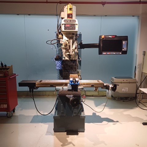
MACHINE SPECIFICATION CHART
| Parameter | Value |
|---|---|
| Table Size | 49″ x 9″ |
| T-Slots (Number x Width) | 3 x .63″ x 2.5″ |
| Travel (X, Y, Z Axis)* | 31″ x 16″ x 22″ |
| Quill Diameter | 3 3/8″ |
| Maximum Quill Travel | 5″ |
| Spindle Taper | R8 |
| Spindle Speed Range RPM | 40 - 600, 300 - 5000 |
| Spindle Center to Column Face | 18.5″ |
| Head Swivel (side to side) | +/- 90° |
| Quill Feeds per Revolution of Spindle | 0.0015/0.003/0.006″ |
| Spindle Motor HP | 3 HP |
| Power Requirements | 200-240V, 3P, 27A |
| Maximum Weight of Workpiece | 1320 lbs |
| Height Of Table From Bottom Of Bed | 36.75″ |
| Max Spindle Nose To Table | 25.5″ |
| Min Height | 86.625″ |
| Max Height | 98.75″ |
| Width Of Machine Including Table | 71.25″ |
| Overall Length With Electric Door Closed | 73.31″ |
| Overall Length With Electrical Door Open | 93.88″ |
| Overall Width Inc Full Table Traverse | 102.53″ |
| Footprint Of Machine | 23.13″ x 40.5″ |
| Weight Net / Shipping Lbs. | 3200 / 3500 |
| Rapid Traverse X, Y, Z | Mechanical Handwheels: 250 IPM on X, Y and Z Electronic Handwheels: 400 IPM on X and Y, 250 IPM on Z |
| Coolant Reservoir Capacity | 10 gallons |
| Drilling Max Capacity (diameter) | 1″ dia. |
| Milling Max Capacity | 3 inch³/min |
| Tapping Max Capacity | ¾ - 10 |
MARCHING OPERATION
Surfboard Milling Process
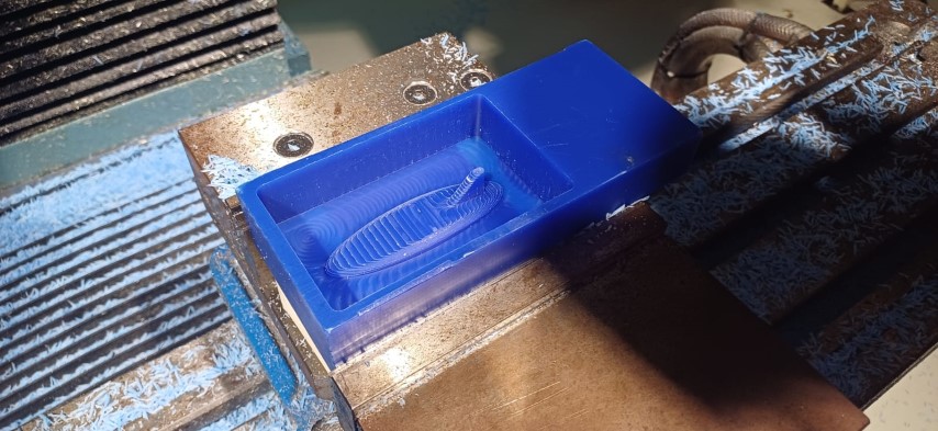
STOCK MATERIAL
i used a block of machining wax to machine the mould out of
.jpeg)
Setting up the Machine
Before milling, several operations must be completed. Begin by setting the origin: attach the edge finder and adjust the tool offset. Once set, load the program and adjust the tool offset for each tool used to ensure precise machining.
Edge Finder
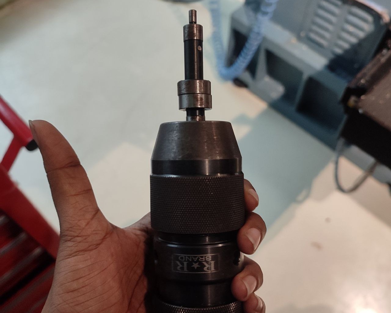
Secure the material, then use Manual wheels or the machine interface with an edge finder to establish X and Y coordinates. Next, set the absolute X and Y axes. Adjust the Z axis by lowering the tool, and set the reference Z axis by moving the tool downward again to maintain the fixed origin during tool changes.
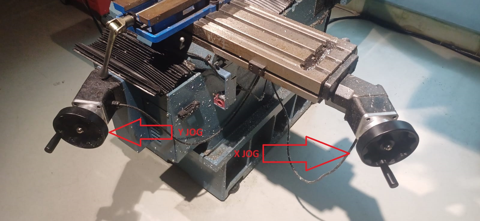
X and Y Jog
Adjust the X and Y axes using the rotary handles.
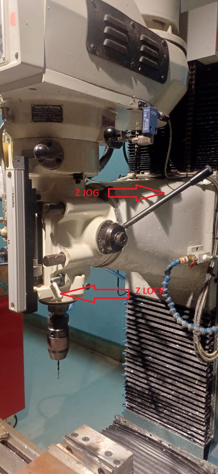
Z Jog
Use the rotary handle to adjust the Z axis; lock the movement with a small lever.
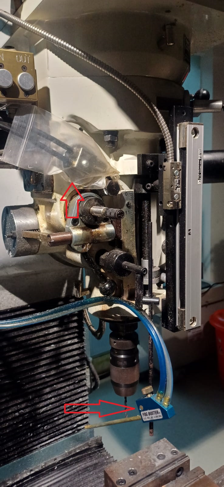
Coolant
For wax, use only air to remove chips; coolant is unnecessary.
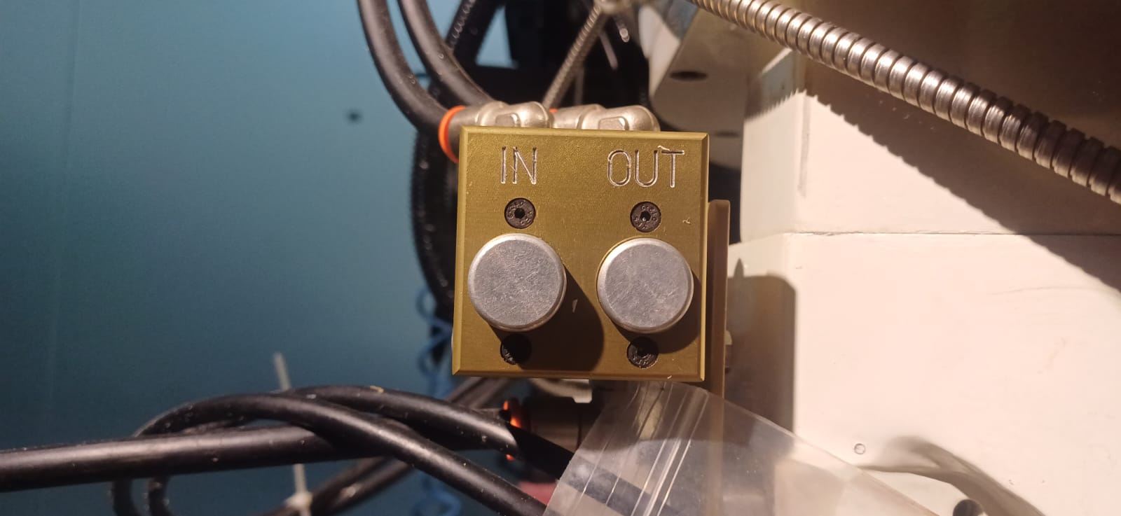
In and Out
Press "Out" to remove the tool module from the spindle and "In" to add a new module.
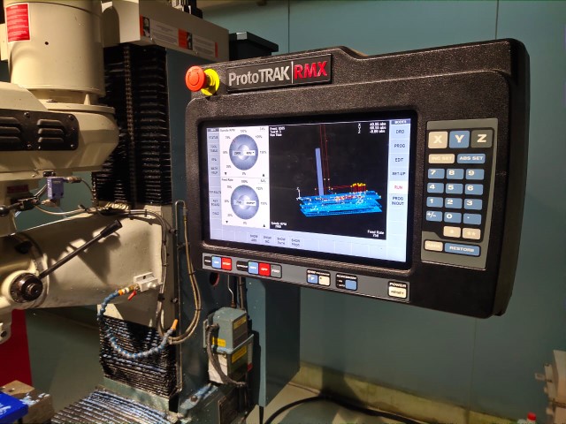
Uploading Program and Tool Setup
Once the origin is set, the next step is to upload the program. Click on "Prog In/Out" on the screen and add the file. Then, add the tool details such as diameter, number of flutes, etc., by clicking on "Tool Table". Before running the milling codes directly, a "trial run" can be performed to ensure all parameters are correct and the work is done properly. Once satisfied, click on "CNC Run" for the machine to start milling.
machining Processes
Visual Representation and Monitoring
The machine provides an extra feature of giving a live visual representation of the toolpath during the process, which helps in monitoring and optimizing the milling process.
Completion and Finishing
i repeted this procces for the other 2 setups using thier respective milling bits
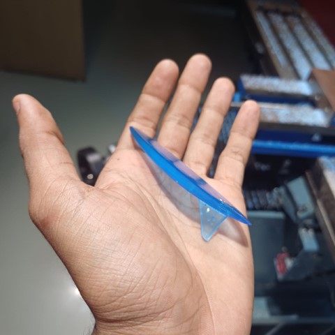
this is the final output that i have recived and it works well for the job
MOULD MAKING
.jpeg)
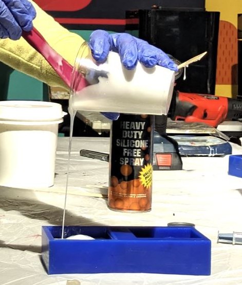
Silicone RTV 1010 is a two-component silicone rubber designed for mold making and prototyping. It includes a silicone rubber base and a curing agent that must be mixed in a precise ratio to initiate the curing process.I used a ratio of 30 ml of curing agent for every 1000 ml of silicone rubber base, which successfully hardened the mold.
To determine the amount of silicone needed, I first measured the approximate volume of the surfboard using water. Based on this measurement, I calculated the required amount of silicone and added the appropriate amount of hardener to ensure proper curing. Once the silicone mixture was ready, I poured it into the mold, ensuring even coverage and eliminating any air bubbles. To aid in releasing the cured mold from the surfboard, I applied a mold release spray. This process resulted in a high-quality mold that accurately replicated the shape of the surfboard, ready for casting.
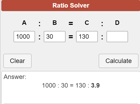
i used around 130 grams of slilcon and it was said to use 30grams of hardener for 1000grams of silicon so did teh math and found out i need around 3.9 milligrams
i used a heavy-duty silicon spray to make sure that the mould will be easy to remove
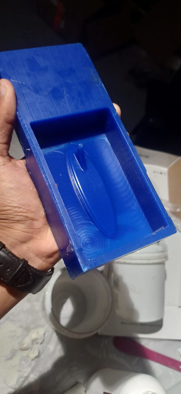
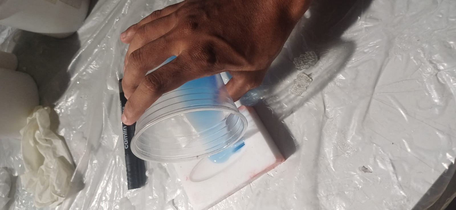
then i pored the silicon into my wax master mould
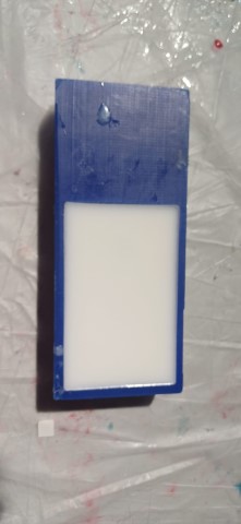
and i let it cure for 24 hrs and then i removed the mould using compressed air it made it very easy and came out easyly
CASTING
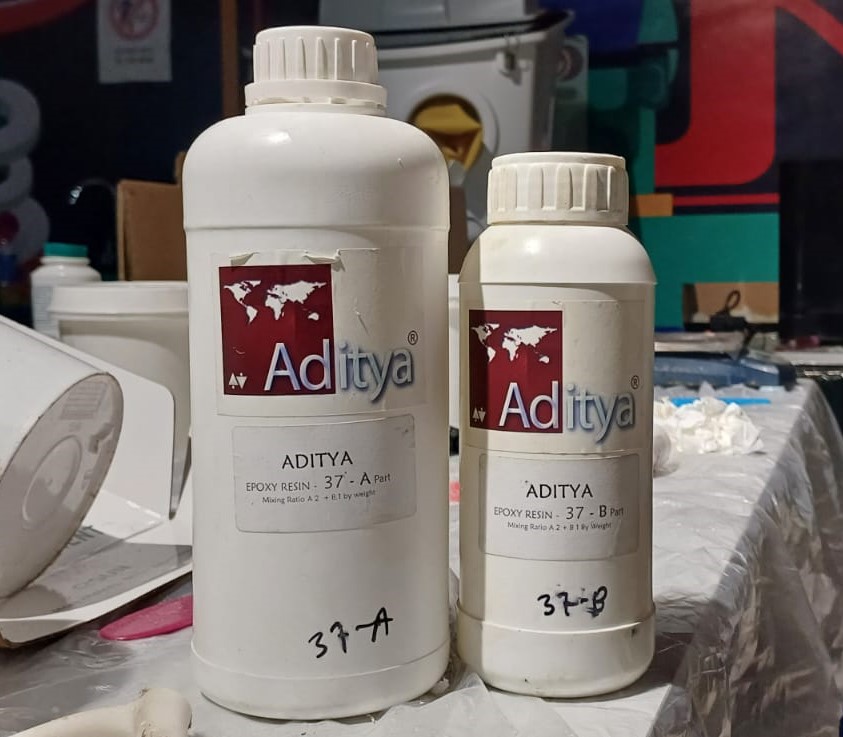
Aditya Ultra Clear Cast Epoxy 37
the resin i used is Aditya Ultra Clear Cast Epoxy 37 which is a general quality epoxy for table top casting. It is comparable to any epoxy available in the market.
It can also be cast into Silicone Moulds to Create Crafts. Pigments are available to make Opaque Colour Castings. It comes in Part A and Part B.
Features
- Transparent Clear
- It’s like water so flows into each and every corner of mould.
- No grinding or sanding after casting.
- Easy Part A 100 parts: Part B 50 parts mixing ratio.
- Non-Yellowing
i followed the same procedure above to determine the volume like teh silicon
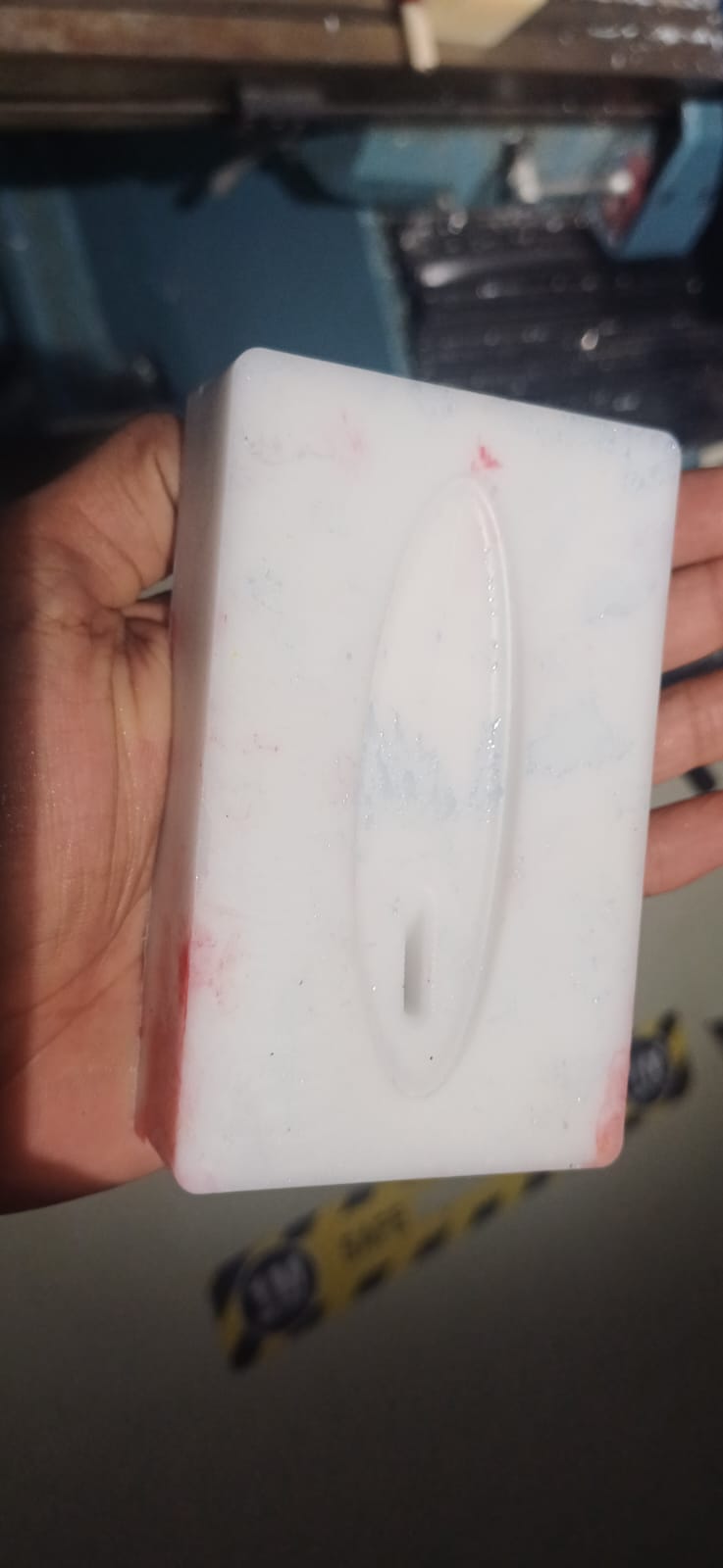
Then, I used a 2:1 resin mixture to cast the part. I mixed the resin and added the necessary colorant, thoroughly mixing it until the desired color was achieved. Once the resin was ready, I poured it into the prepared silicone mold, ensuring complete coverage and filling any intricate details.
i used around 30 milligrams of resin to cast the surfboard, and i slowly poured the resin to the silicon mould
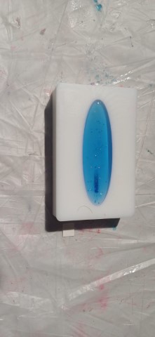
after poring i found out there are some bubbles visible so i planed a diy method to fix it
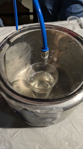
DEGASSING
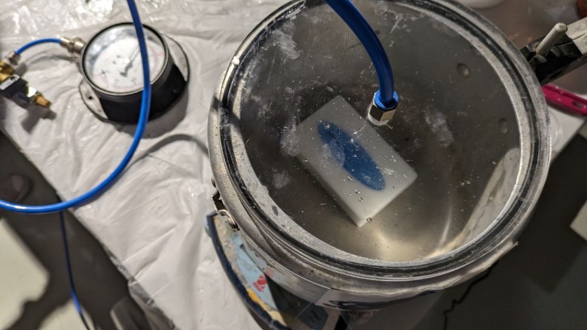
Before pouring the resin, I used our DIY degassing chamber, which is made from a pressure cooker (india is not for beginners). I employed a vacuum pump to pull out the air and degas my resin, ensuring a smooth and bubble-free casting.
When I degassed the part after it was molded, the resin started to overflow. This overflow occurred because the degassing process caused the resin to expand and exceed the capacity of the mold, resulting in spillage.
and it took around 24hrs to harden but i was stillflexing so i kept it for 72 hours and it was hardened well
volla the final surfboard looks nice and detailed