Group Assignment
Individual Assignment
Table of Contents
Week 4 Work Plan
.jpg)
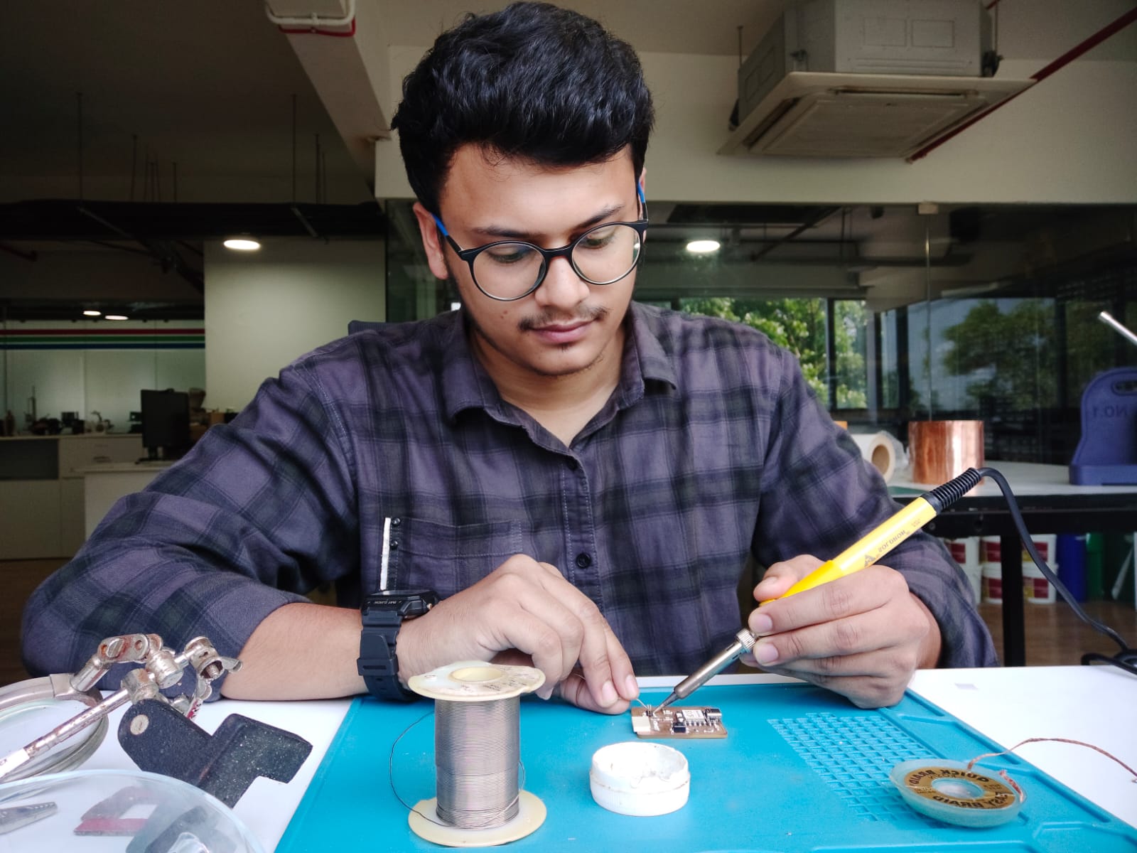
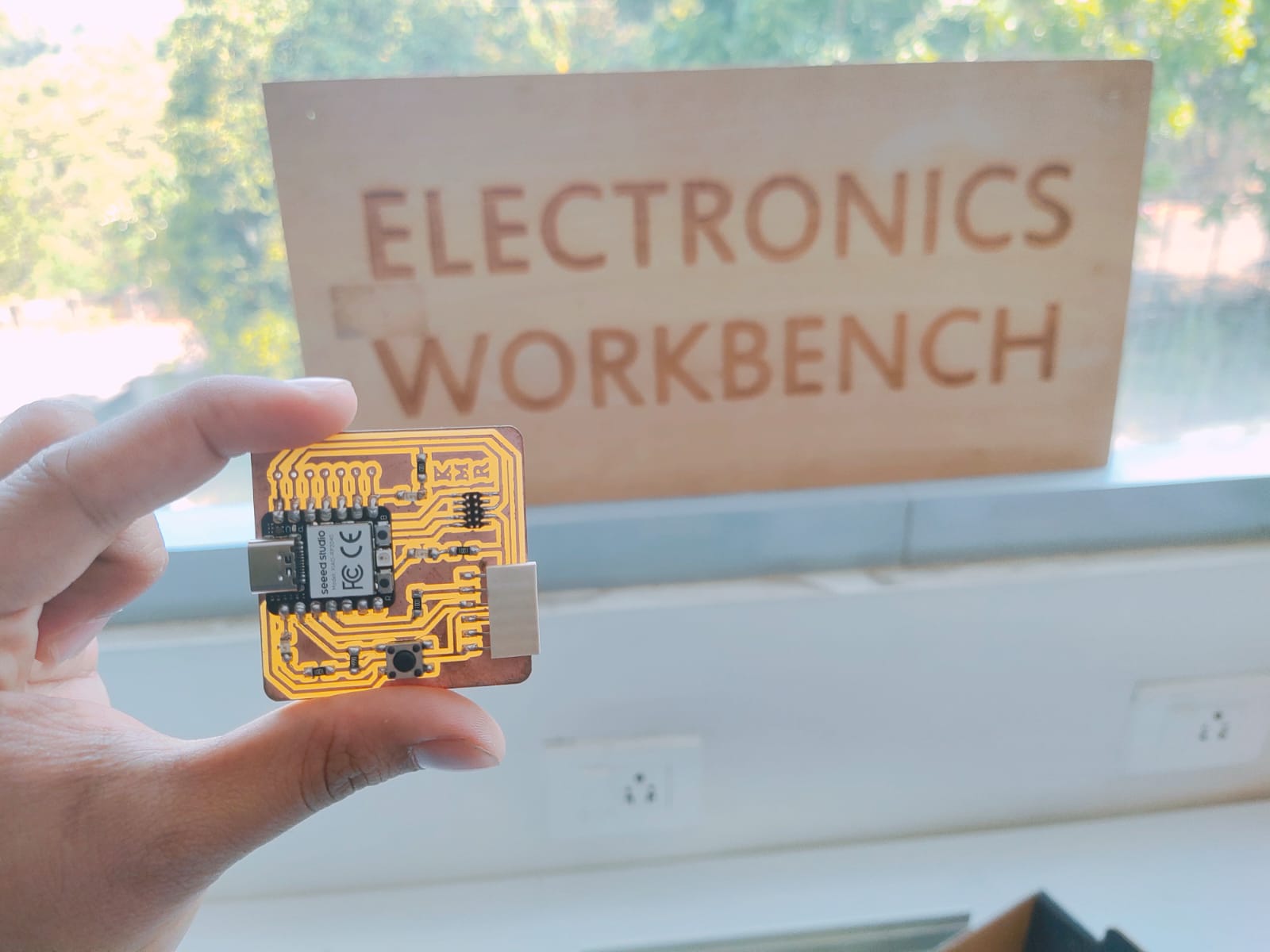
Hero Shot

Group Assignment Result
PCB
PCB stands for "Printed Circuit Board." It is a critical component in the construction of electronic circuits and serves as a platform for the mechanical and electrical connections between various electronic components. PCBs are widely used in the design and production of electronic devices ranging from simple gadgets to complex systems.
Key features and characteristics of PCBs include:
| Substrate Material: | PCBs are typically made of a non-conductive substrate material, most commonly a type of fiberglass reinforced with epoxy (FR-4). Other materials such as polyimide or metal-core substrates may be used depending on the specific requirements of the application |
| Conductive Traces: | Copper foils are laminated onto the substrate, and these thin sheets of copper are etched to form the conductive pathways or traces on the board. These traces provide the electrical connections between different components. |
| Components Mounting: | Electronic components, such as resistors, capacitors, integrated circuits, and other devices, are mounted onto the PCB. The components are soldered onto the conductive traces, creating a secure and reliable connection. |
| Through-Hole and Surface Mount Technology (SMT): | PCBs support different methods of component mounting. Through-hole technology involves components with leads that pass through holes in the board and are soldered on the opposite side. Surface Mount Technology involves soldering components directly onto the surface of the PCB. |
| Layers: | PCBs can have multiple layers, with each layer containing its own set of traces and components. Multi-layer PCBs are used for complex circuit designs, allowing for more compact and efficient layouts. |
| Silkscreen: | A layer of silkscreen, usually applied in white, provides markings on the PCB. These markings often include component outlines, reference designators, and other information to assist with assembly and maintenance. |
| Pads and Vias: | Pads are areas on the PCB where components are mounted and soldered. Vias are holes filled with conductive material that connect different layers of the PCB. |
| Design Software: | PCBs are designed using specialized software that allows engineers and designers to create the layout of the circuit, define the traces, and position the components. Popular design file formats include Gerber files and Excellon files. |
Types of PCBs
| Single-Sided PCBs: | These boards have conductive traces on only one side of the substrate. Components are mounted on one side, and the other side is typically used for soldering. |
| Double-Sided PCBs: | Conductive traces are present on both sides of the substrate. Components can be mounted on both sides, and vias (plated holes) provide electrical connections between the layers. |
| Multi-Layer PCBs: | These boards have more than two layers of substrate, with conductive traces running through internal layers. Used for complex circuits where space is a premium or where specific design requirements are essential. |
| Rigid PCBs: | Standard PCBs with a rigid substrate, commonly made of fiberglass-reinforced epoxy (FR-4). Suitable for applications where the board does not need to be flexible. |
| Flexible PCBs (Flex PCBs): | Designed to be flexible, allowing the board to bend or conform to a specific shape. Often used in applications where flexibility or compact form factors are crucial. |
| Rigid-Flex PCBs: | Combine the features of both rigid and flexible PCBs. Suitable for applications requiring both rigid and flexible sections in a single design. |
| Ceramic PCBs: | Use a ceramic substrate, offering excellent thermal properties and electrical insulation. Suitable for high-power and high-frequency applications. |
FR PCB
FR PCB stands for Flame Retardant Printed Circuit Board, and it typically refers to PCBs made using flame-retardant materials. The most common material used for FR PCBs is FR-4, which is a flame-retardant epoxy laminate. FR-4 is widely used in the electronics industry due to its excellent electrical and mechanical properties.
Some variations and types of FR PCBs based on different considerations:
| FR-1: | Made from a paper-based substrate with phenolic resin. Less common than FR-4 and used in simpler applications. |
| FR-2: | Similar to FR-1 but has a higher flame resistance. Paper-based substrate with phenolic resin. |
| FR-3: | Made from a paper-based substrate with epoxy resin. Provides better electrical performance than FR-2. |
| FR-4: | The most widely used material for PCBs. Made from a woven fiberglass cloth impregnated with epoxy resin. Excellent electrical, mechanical, and thermal properties. Commonly used for rigid PCBs. |
| FR-5: | Similar to FR-4 but designed for applications requiring higher electrical performance. Features a higher Tg and improved dimensional stability. |
| FR-6: | An advanced version of FR-4 with improved electrical and thermal performance. Suitable for high-frequency applications. |
| FR-370HR: | High-performance laminate with enhanced thermal resistance. Used in applications where elevated temperatures and reliability are critical. |
PCB Milling Machine
A PCB (Printed Circuit Board) milling machine is a specialized type of milling machine designed specifically for the fabrication of printed circuit boards. PCBs are crucial components in electronic devices, providing a platform for the connections between various electronic components. PCB milling machines are used to create these circuit boards by removing unwanted copper from a copper-clad substrate.
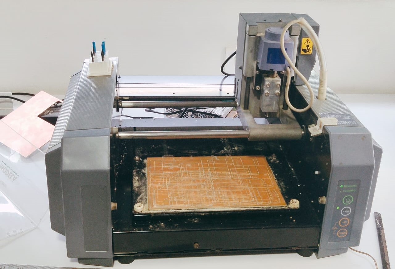
Roland Modela MDX-20
The Roland Modela MDX-20 is a compact and versatile desktop milling machine produced by Roland DG Corporation. It is designed for precision milling, carving, and engraving on various materials such as plastic, wood, resin, and non-ferrous metals. The MDX-20 is often used in prototyping, model making, and small-scale production.
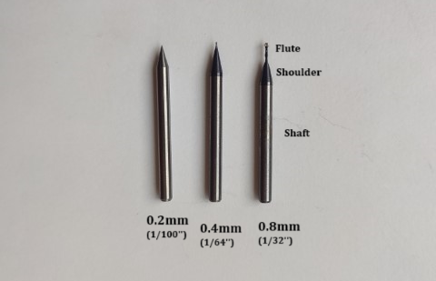
End Mills
PCB milling machines use specialized cutting tools called end mills or PCB milling bits. These tools are designed for precision and are capable of creating fine traces and features on the PCB.
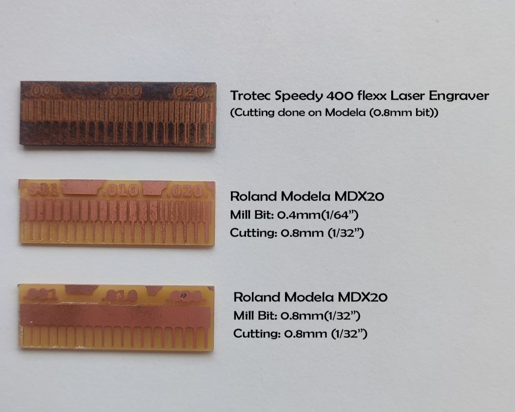
In our lab we used 3 types of end mills, they are;
0.4 mm (1/64”), 0.8 mm (1/32”) and 0.2 mm (1/100”)
- 0.4 mm end mills are used for milling and 0.8 mm end mills are used for cutting.
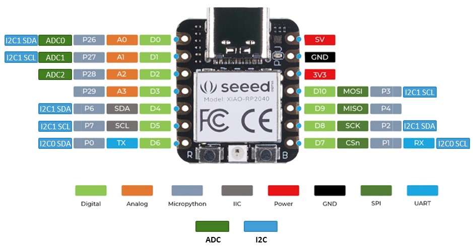
XIAO Microcontroller
The Seeeduino XIAO is the smallest Arduino compatible board in Seeeduino Family. It is an Arduino microcontroller that is embedded with the SAMD21 microchip with rich interfaces as well allowing it to be capable of being a tiny Dev. Board as well.
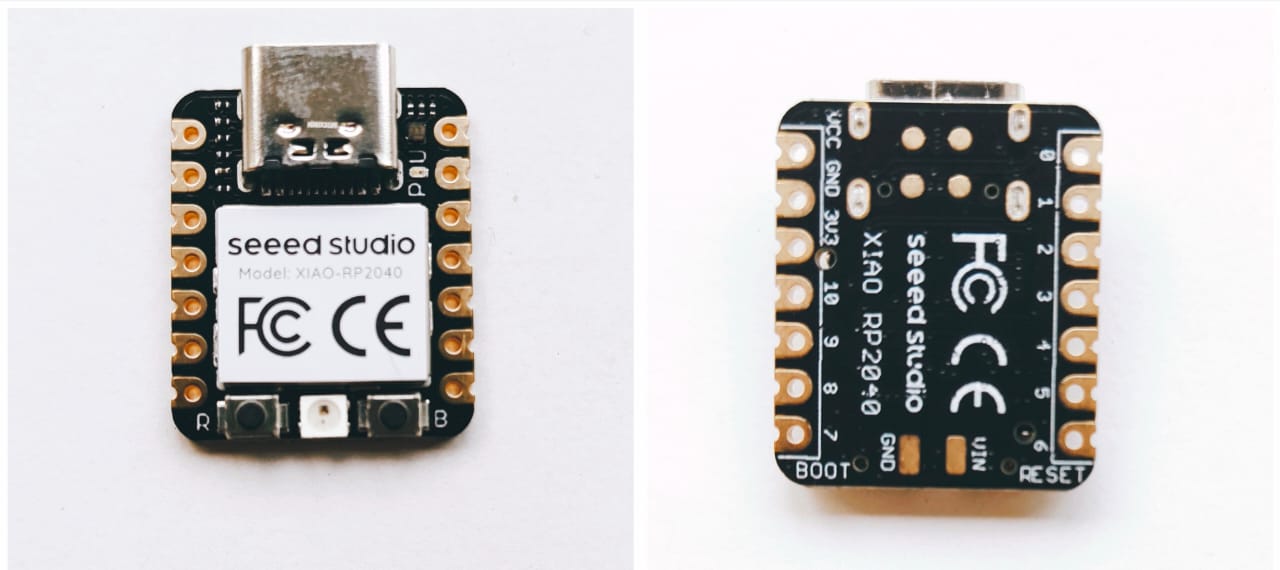
- Seeeduino XIAO has 14 GPIO PINs, which can be used for 11 digital interfaces, 11 mock interfaces, 10 PWM interfaces (d1–d10), 1 DAC output pin D0, 1 SWD pad interface, 1 I2C interface, 1 SPI interface, 1 UART interface, a serial communication indicator (T/R), and a blink light (L). The colours of LEDs (Power,L, RX, and TX) are green, yellow, blue, and blue. Moreover, Seeeduino XIAO has a Type-C interface, which can supply power and download code. There are two reset buttons, which can be short-connected to reset the board.
XIAO Specification
| ITEM | VALUE |
| CPU | ARM Cortex-M0+ CPU(SAMD21G18) running at up to 48MHz |
| Flash Memory | 256KB |
| SRAM | 32KB |
| Digital I/O Pins | 11 |
| Analog I/O Pins | 11 |
| I2C interface | 1 |
| SPI interface | 1 |
| QTouch | 7 (A0,A1,A6,A7,A8,A9,A10) |
| UART interface | 1 |
| Power supply and downloading interface | Type-C |
| Power | 3.3V/5V DC |
| Dimensions | 20×17.5×3.5mm |
Microcontroller Development Board
- A microcontroller development board, also known as a development board or dev board, is a hardware platform used to develop, prototype, and test microcontroller-based projects.
- Microcontroller development boards provide an easy-to-use environment for developers to prototype and develop projects without having to design the entire circuitry from scratch. They often come with built-in programming interfaces and development tools to facilitate code deployment and debugging.
- These boards are commonly used in educational settings, hobby projects, and professional product development to create a wide range of applications such as IoT devices, robotics, automation systems, and more.
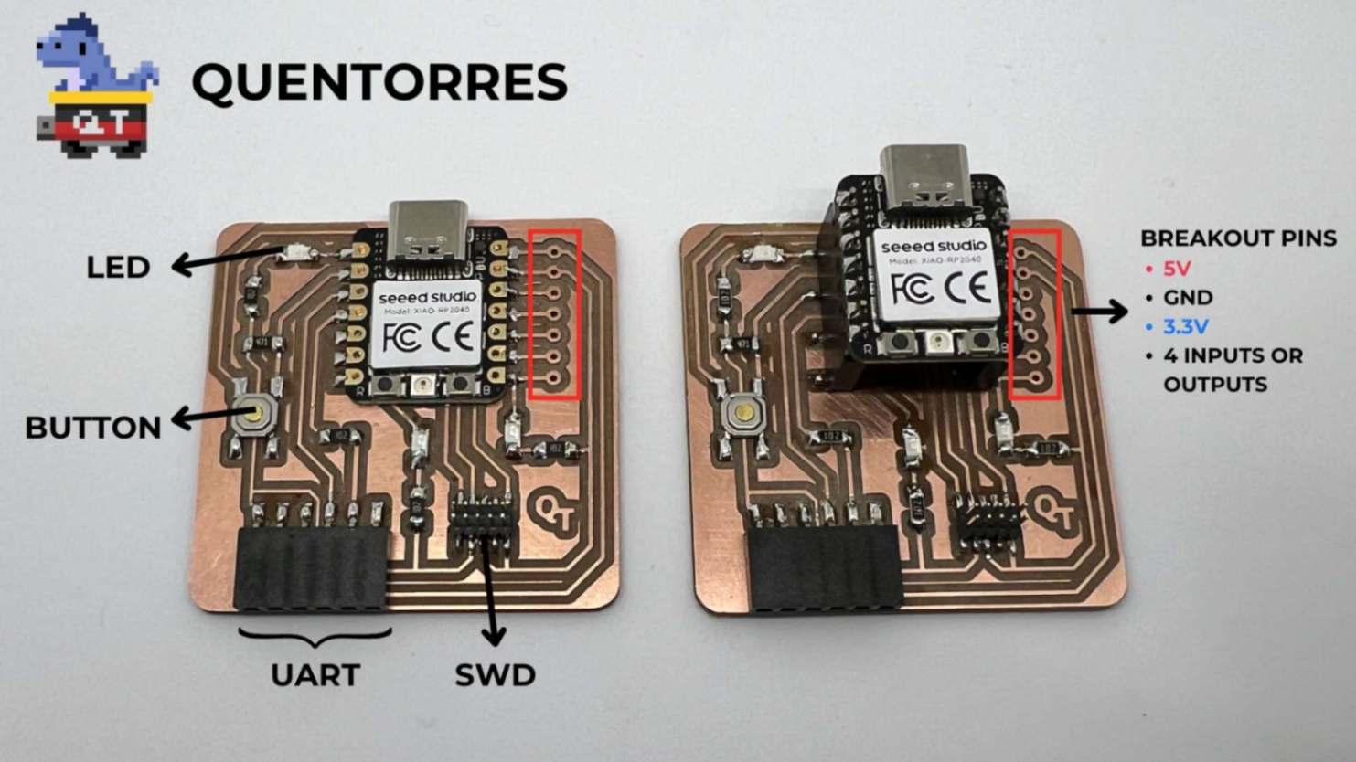
Quentorres Development Board
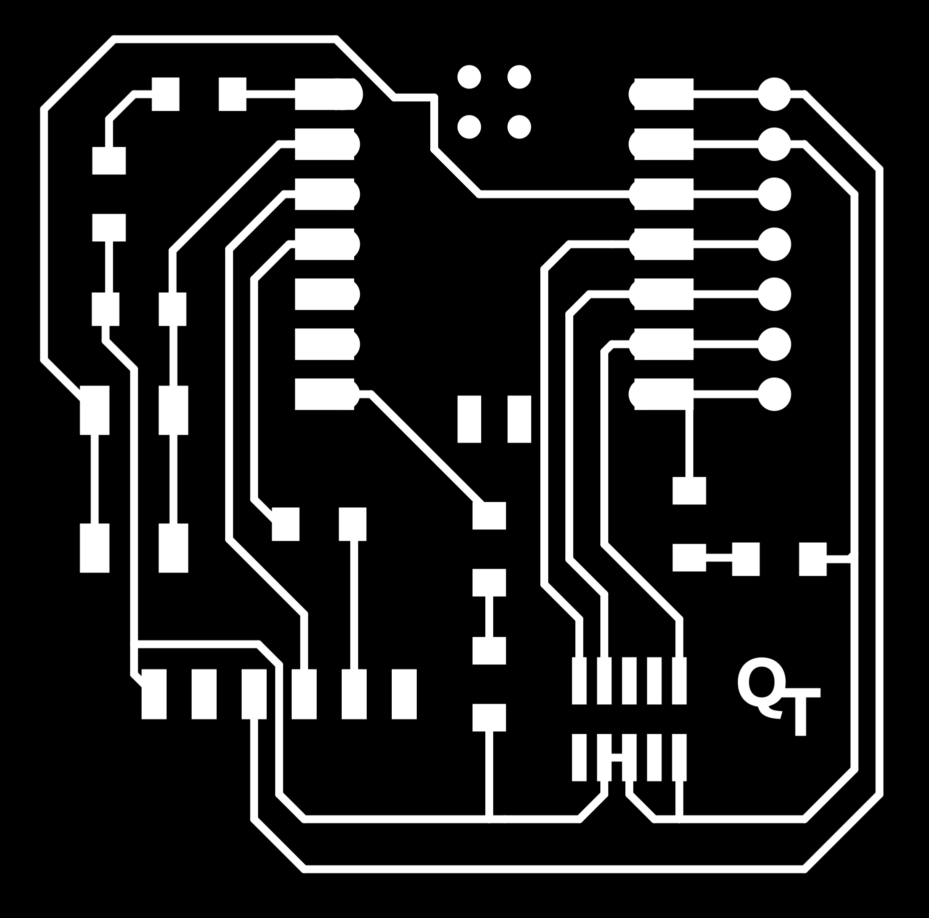
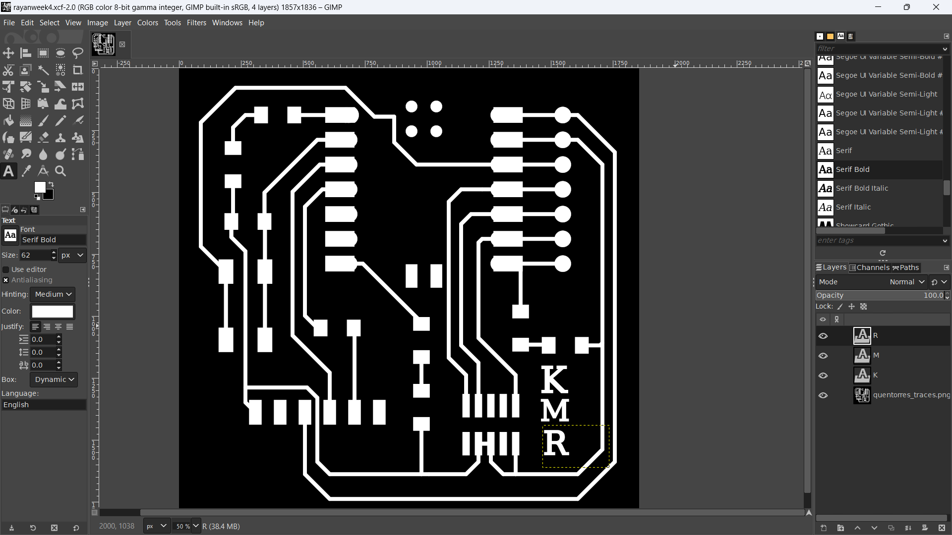
- For the individual assignment involving the creation and testing of a microcontroller development board using a milling machine, the chosen development board is based on the "XIAO" platform and is named "Quentorres." This board was initially developed by Quentin Bolsée and later reimagined by Adrián Torres. In order to customize the board, I downloaded the PNG renders of the Quentorres development board and utilized GIMP to modify the original "QT" marking to "KMR." This customization process likely involved editing the design files to reflect the desired changes before further manufacturing and testing of the board.
- This board can program the new AVR Series 1 and 2, for example, Adrianino, and the ARMs, for example, SAMDino. It also has a button and an LED to learn to program in C, Rust, Go, Micropython, and so on. It has breakout pins in case anyone wants to connect other external elements.
- For more details follow the link below.
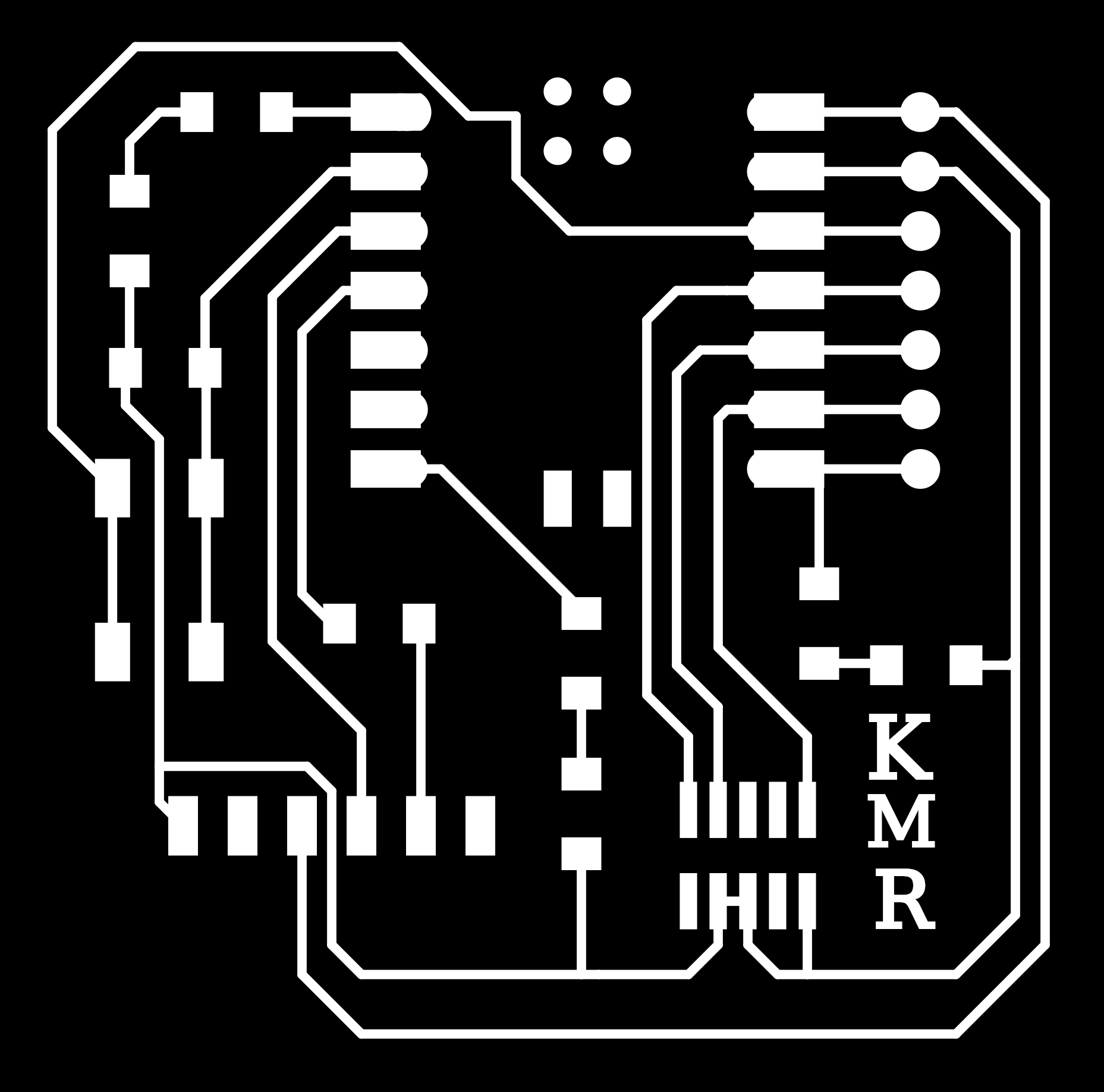
- I removed the “QT” marking using the black colour brush tool and used the text tool to add "KMR”.
- I saved the file and exported it as a png. Later, it was converted into a svg file using the Inkscape trace bipmap tool.
- The image below illustrates the PNG of modified Quentorres PNG renders.
PCB Milling
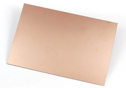
- For PCB milling FR-1 single-sided copper clad is utilized. FR-1 is made from a paper-based substrate with phenolic resin.
- Following the cleaning of the base of the PCB milling machine, I positioned my copper board on a different board that serves as a sacrificial board. The plate of our PCB milling machine is safeguarded by a sacrificial board that is utilised for this purpose. As a result of the end mills moving beyond our board during the drilling process, we all made use of the sacrificial board in order to safeguard both the end mills and the machine plate.
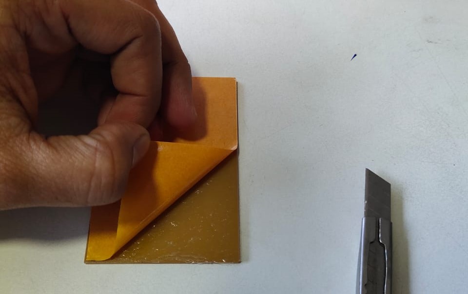
- Once the plate and sacrificial layer are cleaned, stick the double-sided tap below our copper board and place it on top of the sacrificial layer.
- The photo below illustrates the double-sided tap.
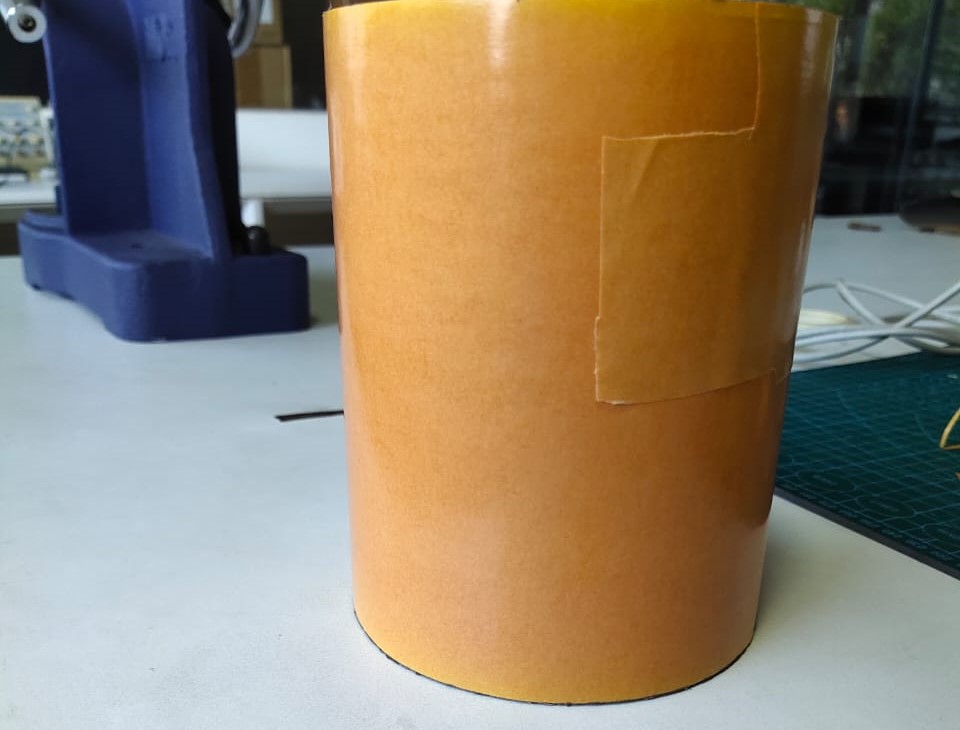
- The photo below depicts the copper board with a double-sided tap stuck to it.
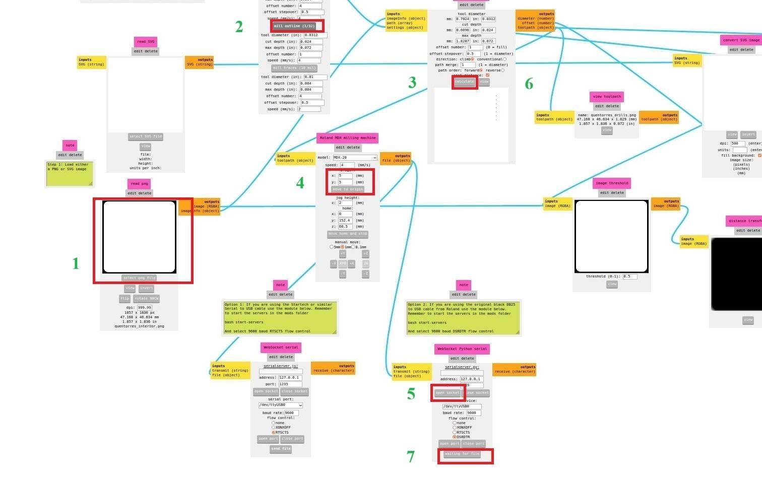
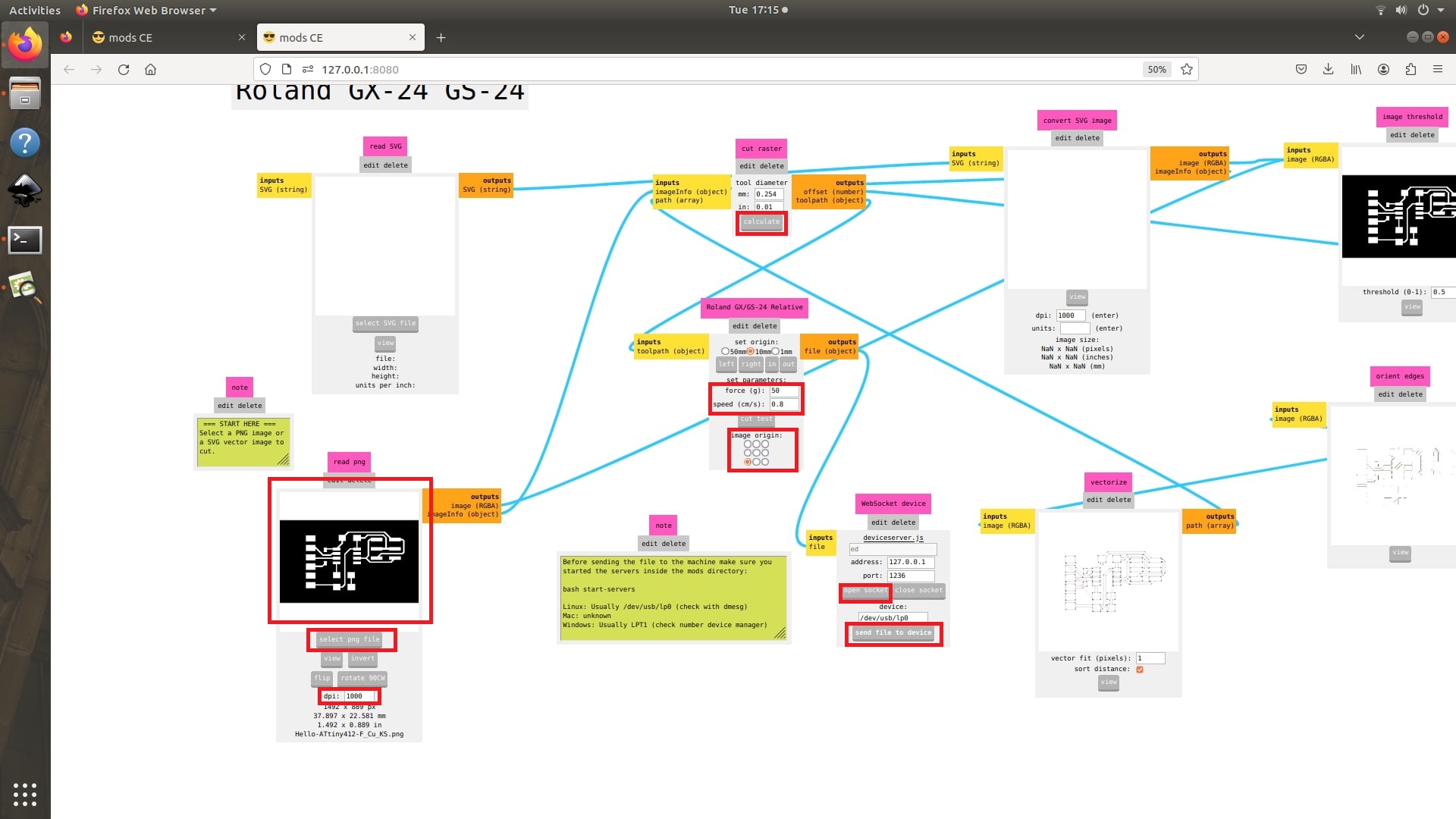
Software Phase [ Mods CE ]
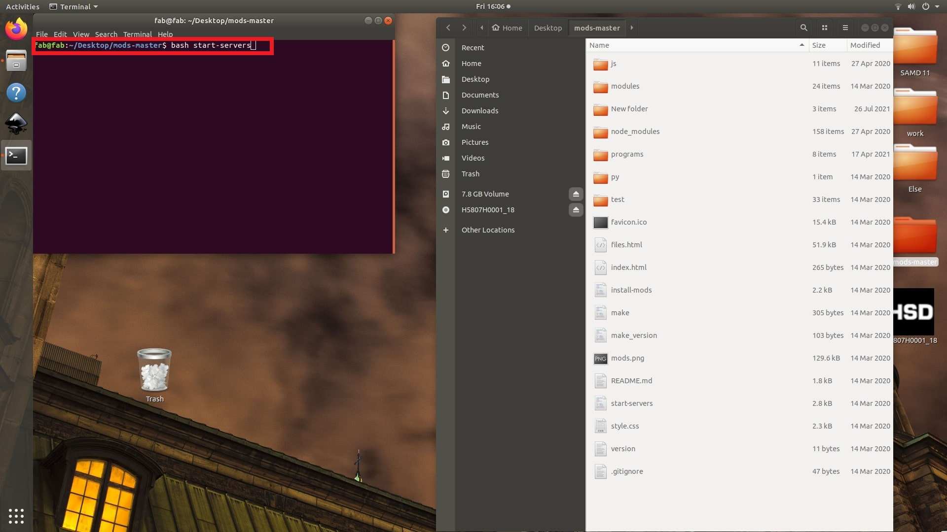
Fab Mods is an open-source web app program that is used as machine software or a driver and works with web socket technology. The moderator replaces the window software with the machine, which provides the machine with the means to cut or mill the given image or vector file.
- Open the mods-master folder, right-click, and select “open terminal". From the terminal, type the following command:
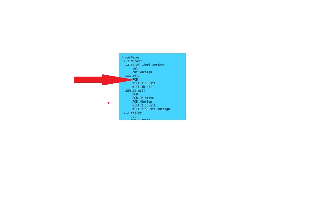
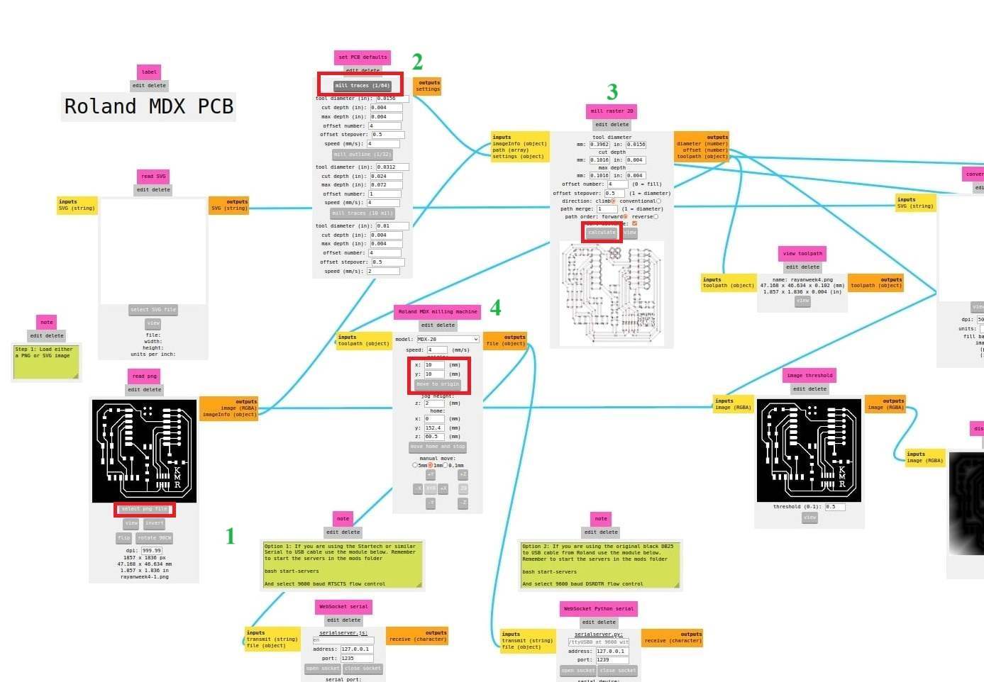
- Then right-click on the page and navigate to "programs" the select "open program", select "MDX Mill", and select “PCB”.
- Once the Mods CE interface is open, open our file. If the file is in SVG, open it from the “read SVG tab”. If the file is in PNG, open it from the read PNG file.
- Here, we used a PNG file because PNG is a lossless image compression format that uses spatial compression to preserve the original image quality. This means that PNG cannot be compressed further without losing quality.
- From “set PCB defaults,” select “mill traces (1/64)”.
- Click on “calculate”.
- Set the origin of the end mills on the “Roland MXD milling machine”. Initially, I set the origin to (10,10), then I changed it to (5,5).
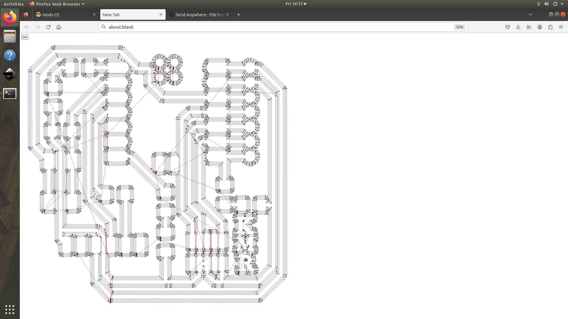
- The image below shows the path of the end mills after being calculated.
- Make sure that the socket is open. If the socket is closed, then click “open socket” from “WebSocket python serial” to open the socket.
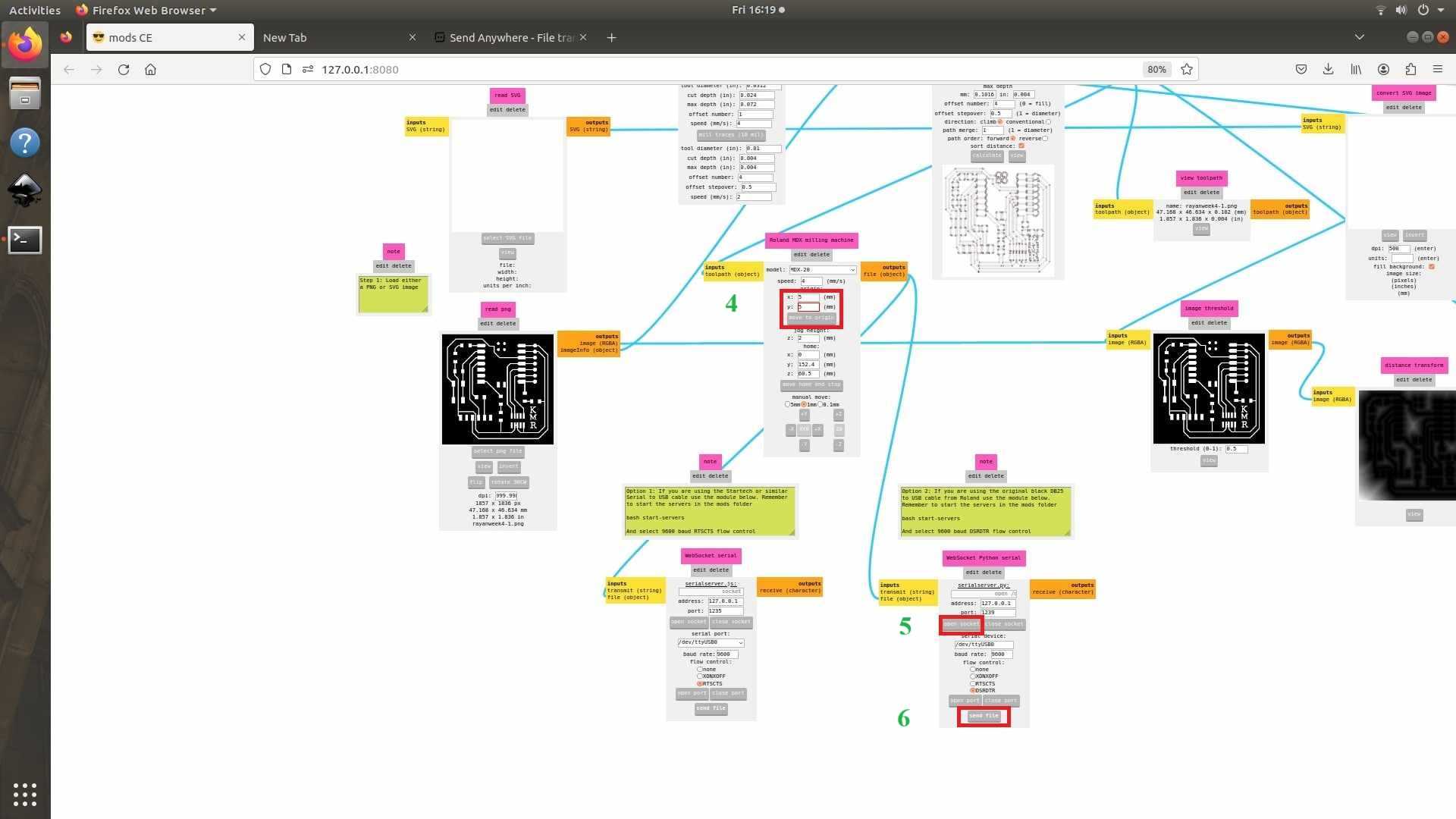
- After performing the milling operation change the end mill to (1/32”)
- Select the PNG file for drilling.
- From “set PCB defaults,” select “mill traces (1/32)”.
- Click on “calculate”.
- Set the origin. In my case I set the origin at (5,5).
- Select “open socket”.
- Click on “send files”.
- The image shown below depicts the path of the end mill for drilling operations.
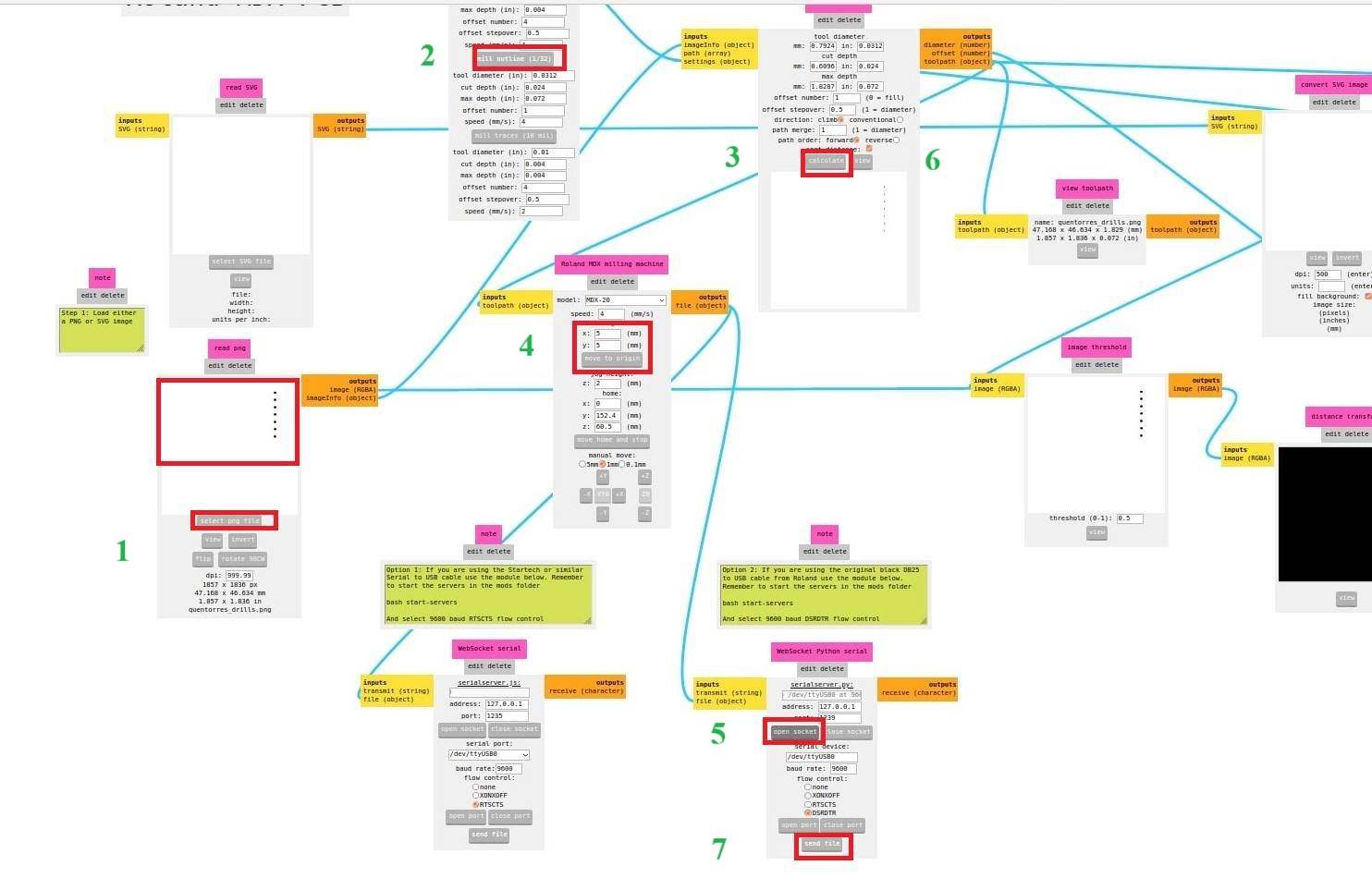
- Finally, after completing the drilling operation, it is time to cut the outside of the PCB.
- Use the same (1/32”) end mill for operate cutting.
- Select the PNG file for cutting.
- From “set PCB defaults,” select “mill traces (1/32)”.
- Click on “calculate”.
- Set the origin. In my case I set the origin at (5,5).
- Select “open socket”.
- Click on “send files”.
Machining Phase
- Initial process is the mill the circuit path on copper board.
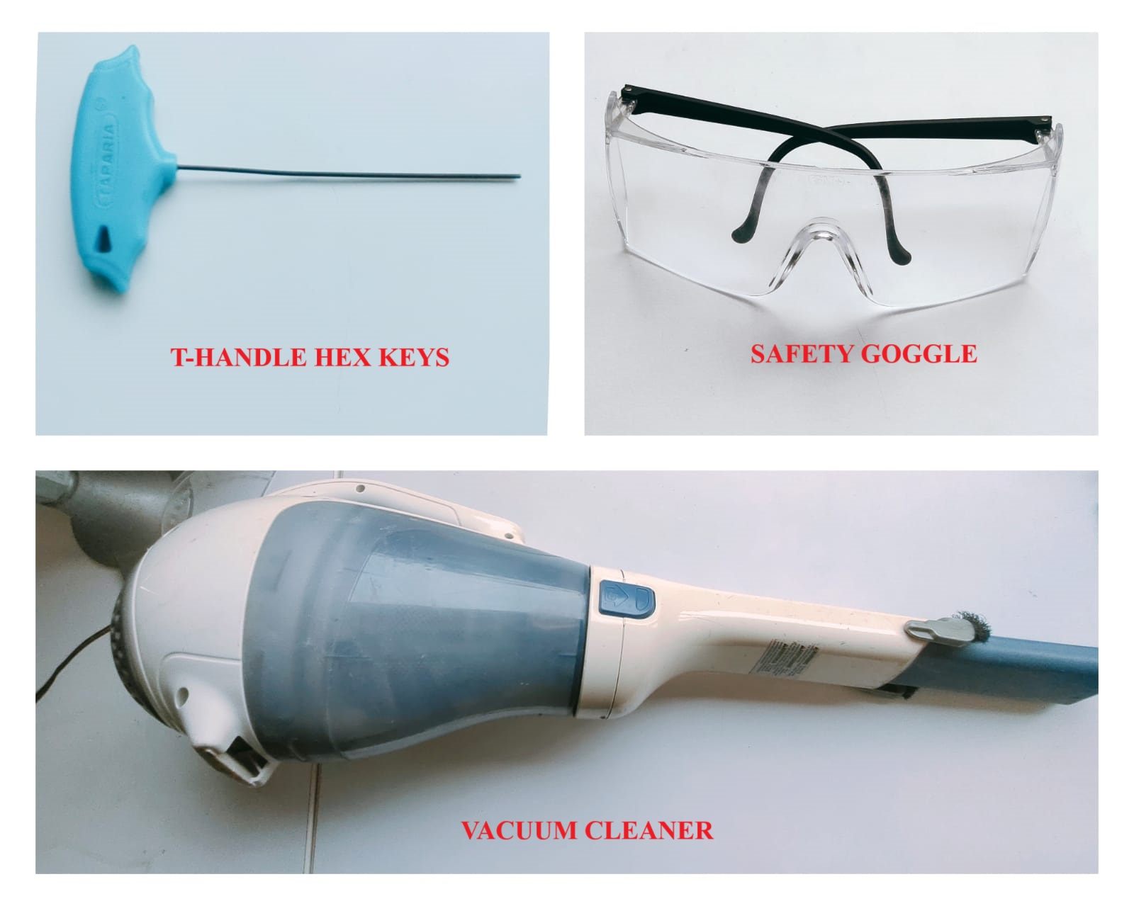
- It is highly recommended to remove the watch before operating the milling machine. Watch may act as a barrier while changing the end mills for milling and cutting operations.
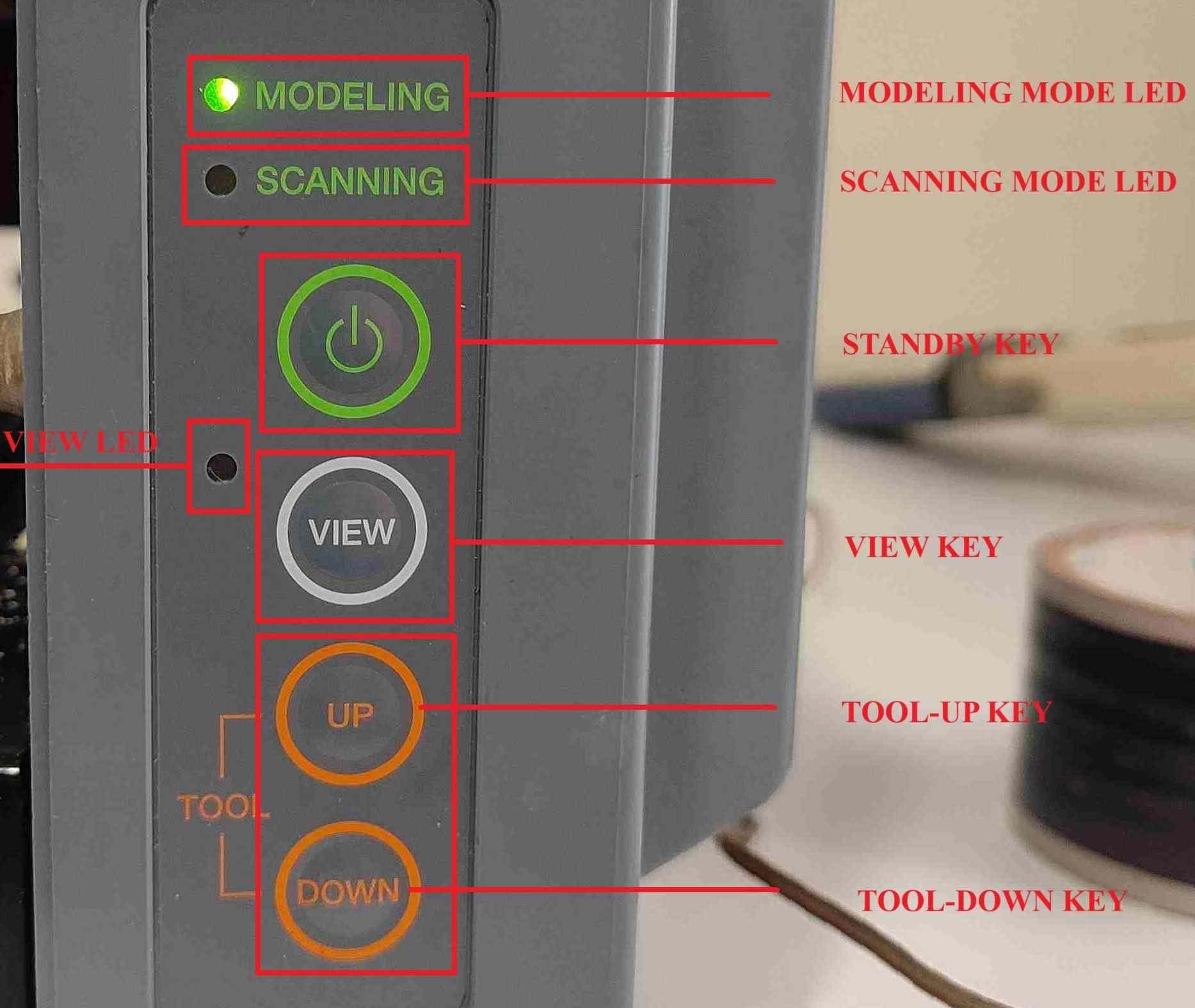
- Turn on the machine
- Change the end mill to (1/64”) for milling.
- Tighten the screw on one side and place the mill as close to the inside as possible.
- Press “view” from the control panel. The end mill moves to the left-hand side, and from the mods, click on Move to Origin. Then the end mill will be placed exactly above the origin point.
- Press and hold the “down key” from the control panel to move the end mill down, and once the end mill is around 1.5 cm above our copper board, remove pressing the “down” key. Loose the screw and move the end mill to the copper plate. Gently press the endmill down and tight both screws.
- Press and remove the “down key” once or twice so a white powder will form on the copper board at the point of contact between the end mill and the copper board.
- From the software side (mods ce), click “send file", and then the milling operation will start to perform.
- For drilling and cutting, change the end mill to (1/32”) by following the same technique mentioned above. Perform the same steps as above (mentioned for milling operations) for drilling and cutting.
- The complete time laps of PCB milling is shown below.
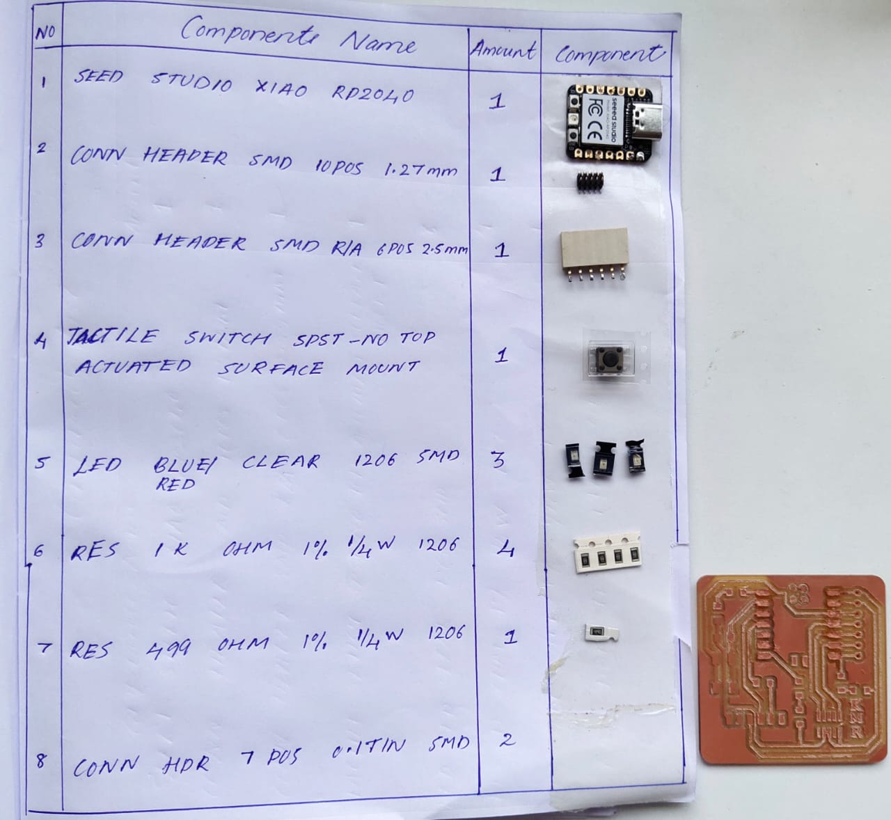
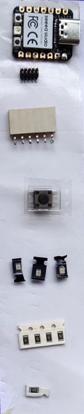
Quentorres Development Board Components List
- The photo below shows the components list for development board.
- For collecting the components from our Fab Lab inventory, I need to add the file from the fab inventory website and request the components.
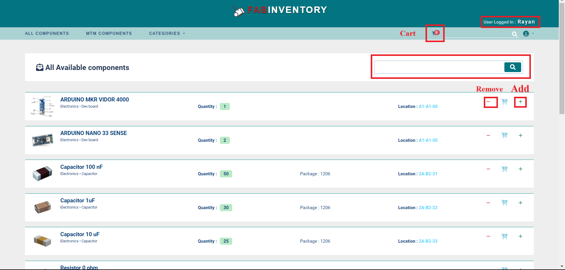
- Once the components are requested, the instructor will approve the component list so that we can take the accepted components from the inventory.
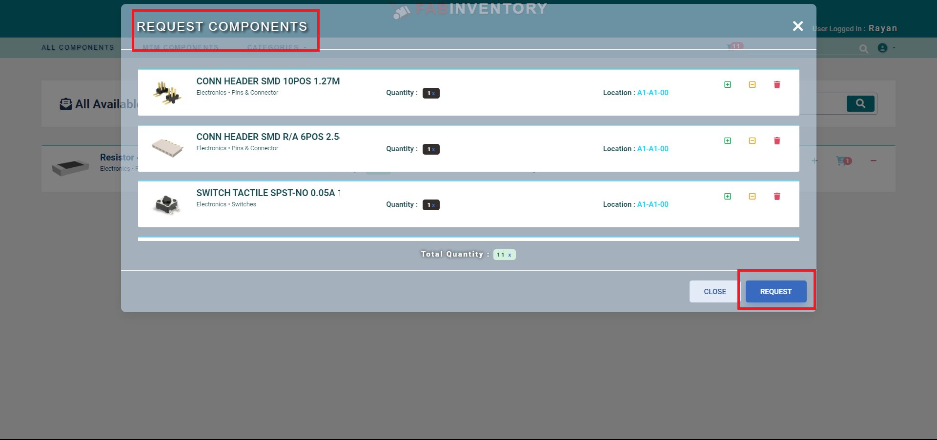
- All the components name and parts are shown below.
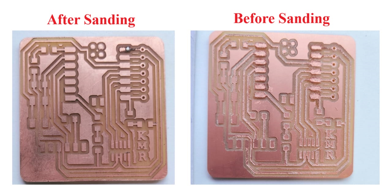
- After milling, the tracks of the PCB were not proper, so I used sandpaper to remove the unwanted materials from the PCB. Removing the oxide layer is important. To remove the oxide layer from the circuit board, I need to use sand paper.
Soldering
Soldering is a process used to join two or more metal components together by melting and flowing a filler metal into the joint. The filler metal, known as solder, has a lower melting point than the metal being joined, allowing it to create a bond without melting the workpieces. Soldering is commonly used in electronics, plumbing, jewelry making, and various other applications.
Basic steps of soldering
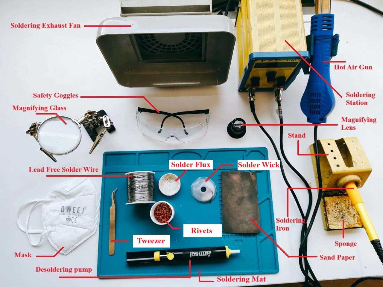
- Gather Materials
Soldering iron or soldering station.
Solder wire (usually a combination of tin and lead or lead-free alloys).
Flux (in the form of a liquid or paste) to clean and prepare the surfaces.
Components or wires that intend to solder.
Safety equipment (safety glasses, heat-resistant gloves).
- Prepare the Work Area:
Choose a well-ventilated area or use a fume extractor to avoid inhaling soldering fumes.
Ensure you have a clean and organized workspace.
- Inspect and Clean the Components:
Clean the surfaces to be soldered using a small brush or cotton swab, and apply flux to remove oxidation.
Check the components and circuit boards for cleanliness and any visible damage.
- Heat Up the Soldering Iron:
Turn on the soldering iron and allow it to reach the appropriate temperature. The temperature can vary depending on the type of solder and the components being used.
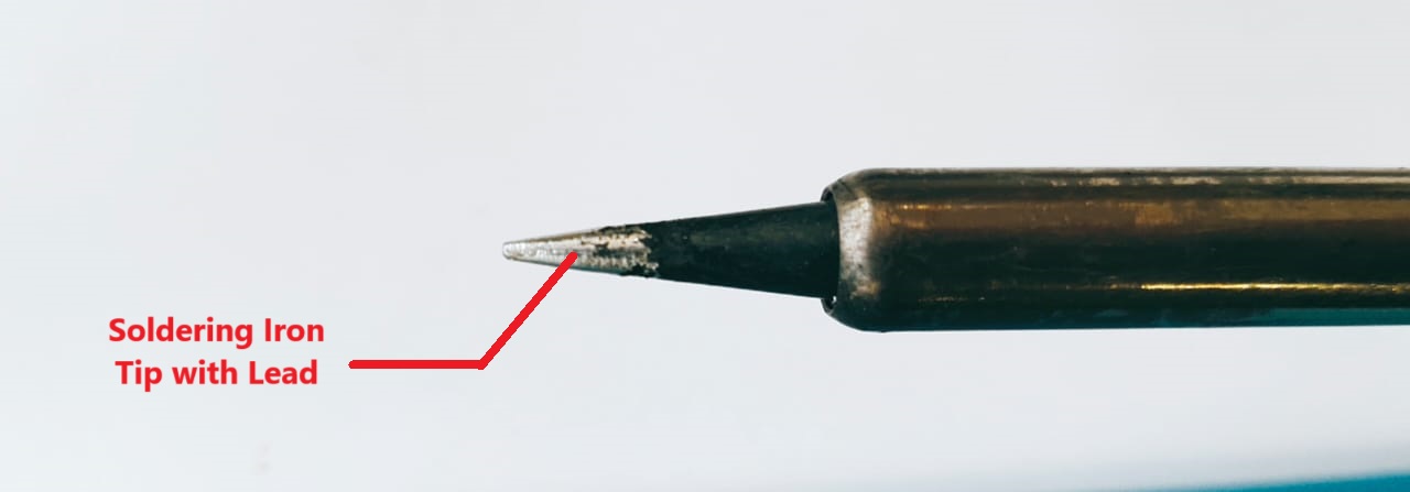
- Tinning the Soldering Iron Tip:
Apply a small amount of solder to the tip of the soldering iron to "tin" it. This helps with heat transfer and improves soldering performance.
- Tinning the Components:
Apply a small amount of solder to the surfaces of the components you are soldering to create a thin layer of solder (tinning). This aids in the soldering process.
- Position the Components:
Align the components to be soldered and hold them in place using a clamp or helping hands tool if needed.
- Apply Heat and Solder:
Touch the soldering iron to the joint, heating both the component and the circuit board pad.
Feed a small amount of solder onto the joint, ensuring it flows evenly to create a solid connection.
Avoid overheating the components, as excessive heat can damage sensitive electronic parts.
- Inspect the Solder Joint:
Once the solder has cooled, inspect the joint. It should have a smooth and shiny appearance.
Ensure there are no solder bridges (unintended connections between adjacent pads or leads) or cold joints (dull and grainy appearance).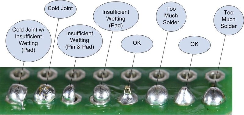
- Clean the Soldering Iron Tip:
Wipe the soldering iron tip on a damp sponge to remove excess solder and oxidation. Retin the tip before moving on to the next joint.
Soldering Safety Measures
- Ensure you have a well-ventilated workspace. If possible, use a fume extractor or work near an open window to minimize exposure to soldering fumes. Keep the workspace clean and organized to avoid accidents.
- Keep a fire extinguisher rated for electrical fires nearby. Avoid soldering near flammable materials. Turn off your soldering iron when not in use, and unplug it when finished.
- Work in a well-ventilated area or use a fume extraction system to remove soldering fumes from the air. Avoid breathing in the fumes directly.
- Handle the soldering iron with care and avoid touching the hot tip. Place the soldering iron on a stand when not in use to prevent accidental burns or fires. Never leave a heated soldering iron unattended.
- Be aware of the materials you are working with, including the type of solder and flux. Some fluxes may produce harmful fumes, so choose low-odor or no-clean flux if possible.
- Inspect your soldering iron and power cord for any damage before use. Ensure that the power cord is in good condition and properly grounded. Use a grounded outlet and follow proper electrical safety procedures.
- Know the location of emergency exits and equipment, such as fire extinguishers. Be familiar with first aid procedures for burns and injuries.
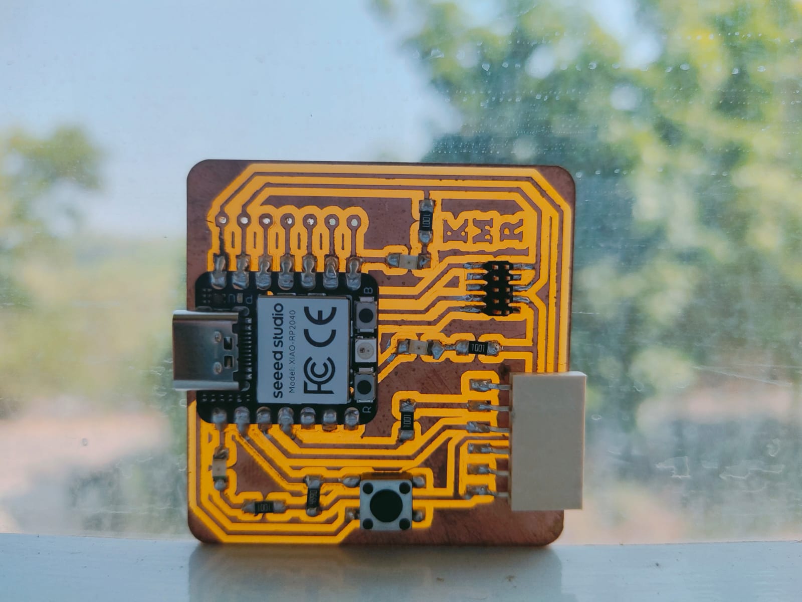
Soldered Quentorres Board
Isopropyl alcohol (IPA)
IPA for Mobile Phone Repairing (Isopropyl Alcohol) is the Best PCB Cleaner. Also called Thinner or PCB Cleaning Liquid. Mainly used for Mobile Repair, Motherboard Cleaning, and Cleaning of Electronic Components in Ultrasonic Cleaner.

Programming the Quentorres Board
XIAO microcontroller can be programmed using Arduino IDE. I have already installed Arduino IDE.
Arduino IDE
The Arduino Integrated Development Environment - or Arduino Software (IDE) - contains a text editor for writing code, a message area, a text console, a toolbar with buttons for common functions and a series of menus. It connects to the Arduino hardware to upload programs and communicate with them.
Arduino IDE Installation
- Follow the link below for Arduino IDE Installation.
XIAO Development Board Programming Setup
- Open the Arduino IDE
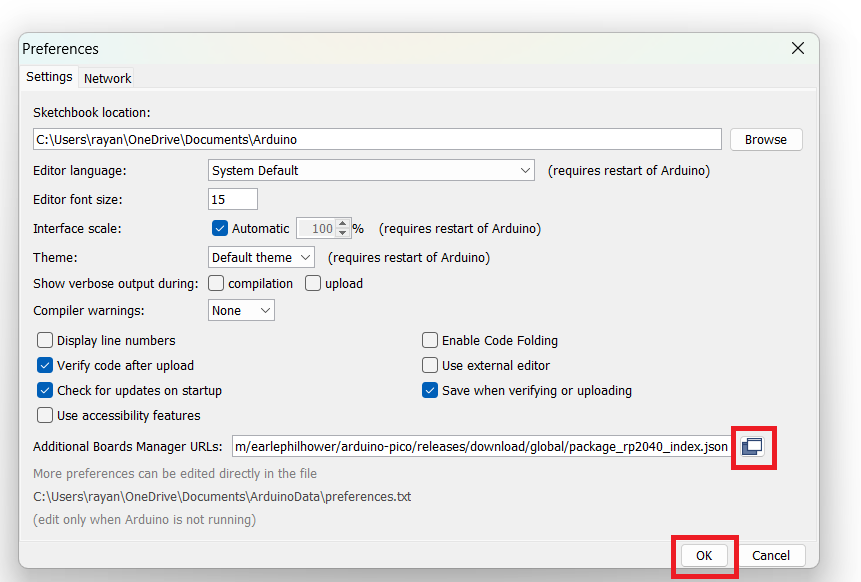
- From file select preference
- Copy and paste the URL below in the “additional boards manager URLS” text box.
- click “OK”
- From “Tools”, select “Board”, then select board manager.
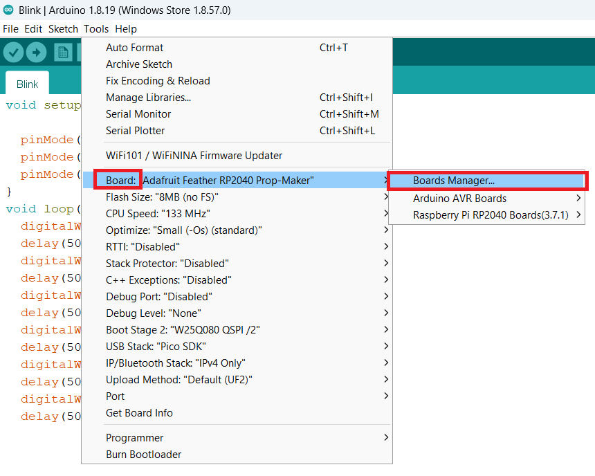
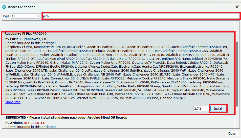
- Search for “pico” and install the board mentioned below.
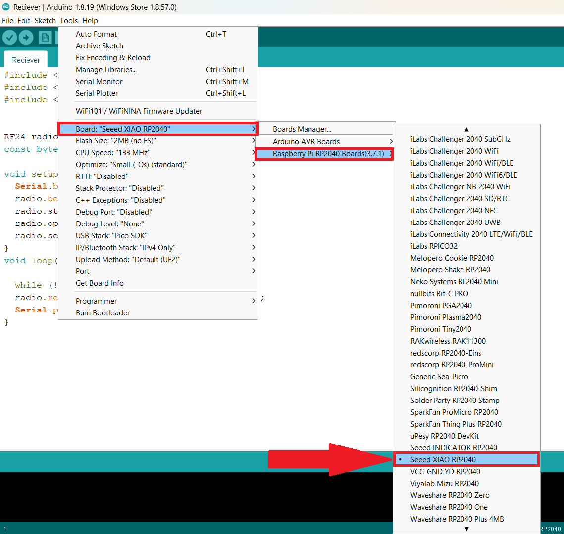
- From Tools, Select “board”, select “Raspberry Pi”, then select “Speed XIAO RP2040”.
- I used a sample blink program to test my board. Compile the code and Upload.
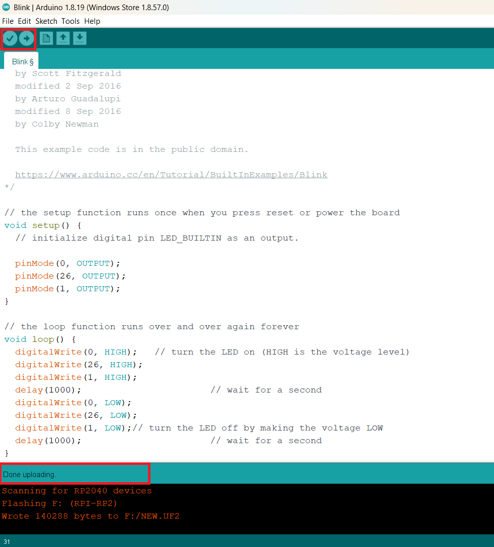
- After testing, I coded for Blink all three LEDs that are used on the board. Each led will turn on for 0.5 seconds, then turn off, and then the second led will turn on for 0.5 seconds and turn off. similarly for the third led.
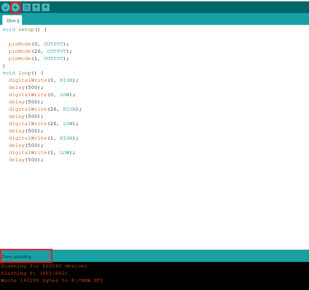
- The code I uploaded to the board mentioned below:
void setup() {

	  pinMode(0, OUTPUT);
	  pinMode(26, OUTPUT);
	  pinMode(1, OUTPUT);
	}
	void loop() {
	  digitalWrite(0, HIGH);
	  delay(500);
	  digitalWrite(0, LOW);
	  delay(500);
	  digitalWrite(26, HIGH);
	  delay(500);
	  digitalWrite(26, LOW);
	  delay(500);
	  digitalWrite(1, HIGH);
	  delay(500);
	  digitalWrite(1, LOW);
	  delay(500);
LED Blinking
Flexible PCB
- Following my completion of the individual assignment as well as the group assignment, I made the decision to experiment with flexible PCB using a Roland GX-24 vinyl cutter. For the flexible PCB tracks, conductive adhesive vinyl was used as the material of choice.
- I have decided to try out the Hello ATtiny412 board for my flexible PCB board. All the details of the Hello ATtiny412 board are provided by following the link below.
- Download the PNG or SVG files of the tracks from the link provided above.
- Initially, I tried SVG file, but MODS was unable to open the SVG file, so I decided to go with the PNG file.
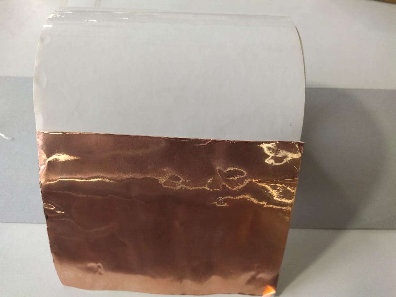
- I tried to cut the tracks directly to the conductive tap, but later it was hard to transfer to the flexible material. So I decided to try using a transfer tape. I cut a piece of conductive tape, stuck it on the transferring tape, and placed that roll on the vinyl cutter. Now, by peeling the transfer tape, I can directly stick the tracks to the flexible material.
- Initially, the vinyl cutter was unable to cut. Later, I found the size of the file was high, and then I changed the dpi to 1000. It works well 🙂.
- I reduced the speed to 0.8 cm/sec from mods and increased the force to 90gf from the control panel of vinyl cutter.

- The vinyl cutter cutting the tracks on the conductive tape.
| COMPONENTS NAME | QUANTITY |
| 1uF Capacitor 1206 | 1 |
| 1k Resistor 1206 | 1 |
| LED 1206 | 1 |
| Schottky Diode SOD-123 | 1 |
| Microcontroller_ATtiny412_SSFR | 1 |
| Conn_PinHeader_UPDI_2x03_P2.54mm_Vertical_SMD | 1 |
| Conn_PinHeader_FTDI_1x06_P2.54mm_Horizontal_SMD | 1 |
- After collecting the components from the inventory, I started to solder them to my flexible PCB.
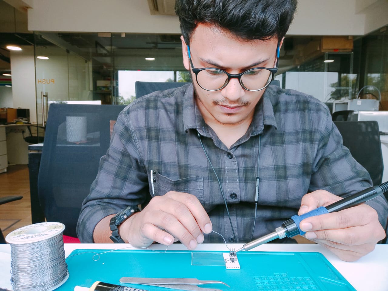
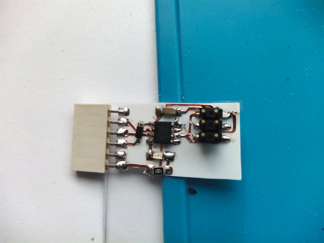
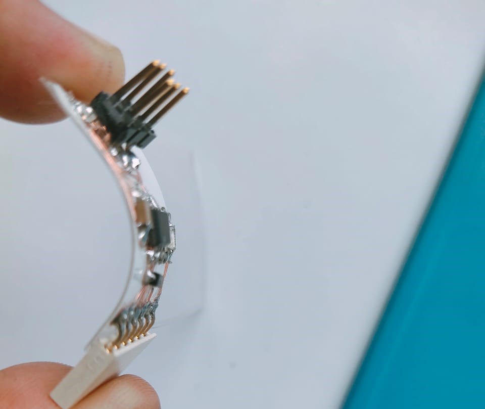
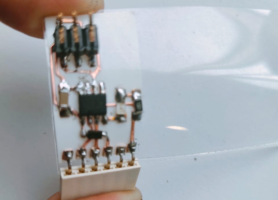
- The photos below illustrate the flexible PCB after soldering.
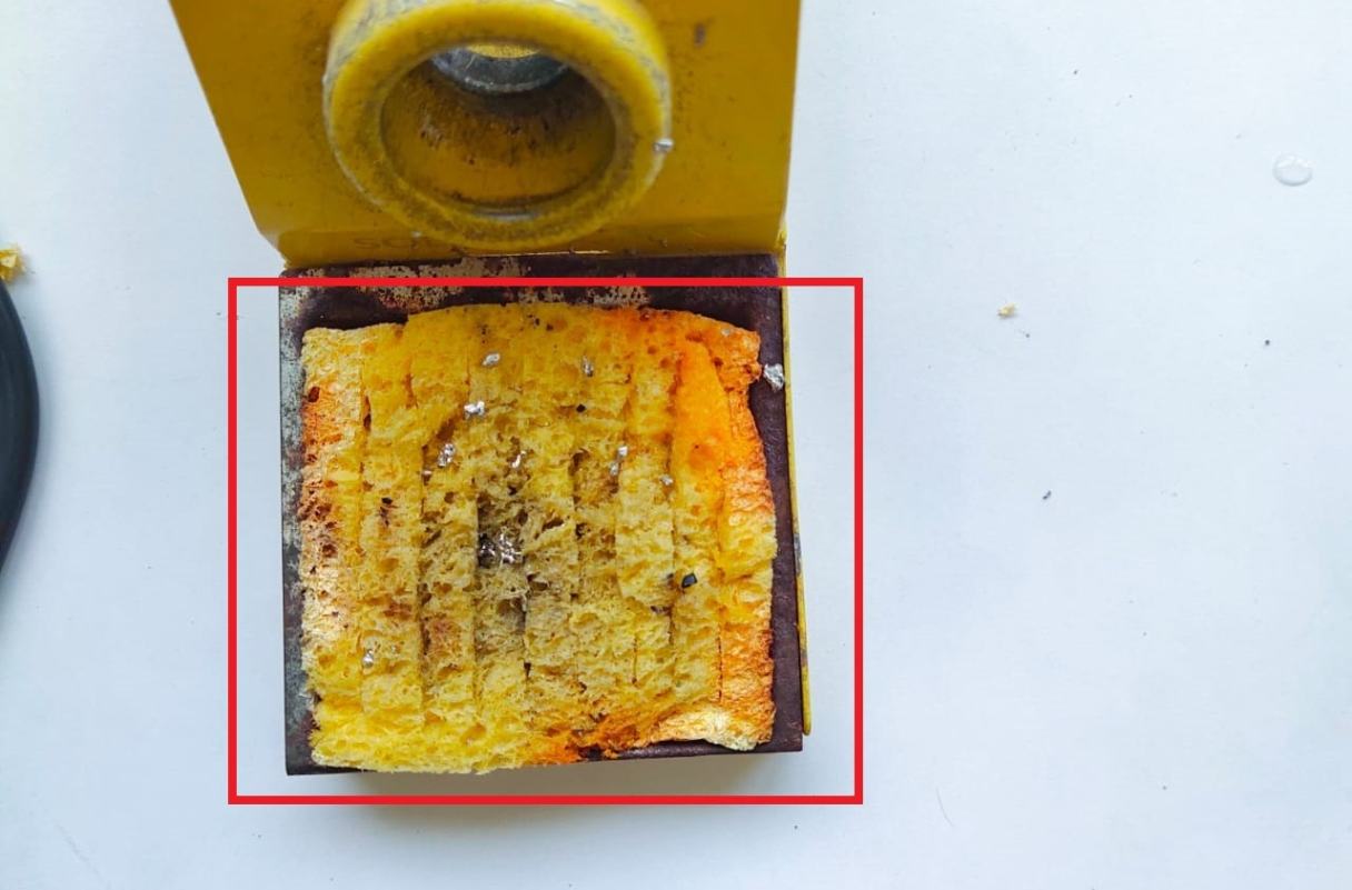
Reflow
Reflow soldering is a process that involves heating an oven to its maximum temperature to melt solder paste. The goal is to create a strong metallurgical bond between the component leads and the PCB pads.
The reflow phase is when the solder paste reaches its eutectic temperature and undergoes a phase change to a liquid or molten state. The time the solder is held above its melting point is important to ensure correct wetting between components and PCB.
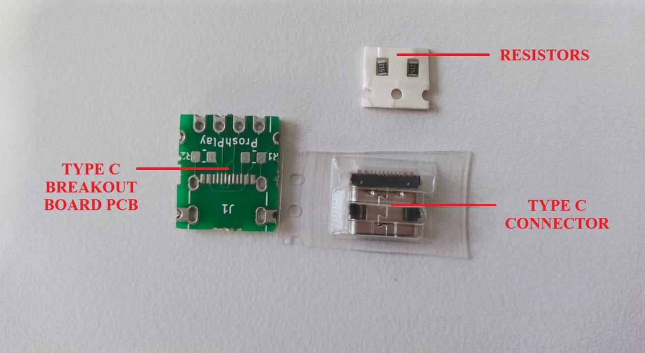
Type-C Breakout Board
For performing the reflow, our instructor gave us a type C breakout board and the components.
- The photo given below illustrates the breakout board with improper edges.
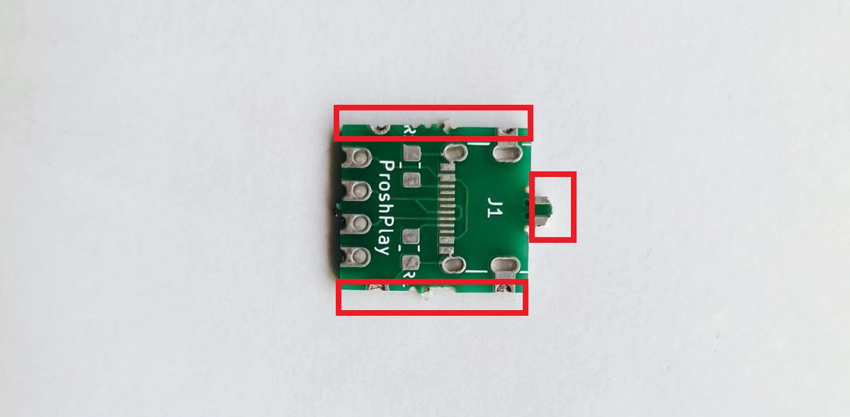
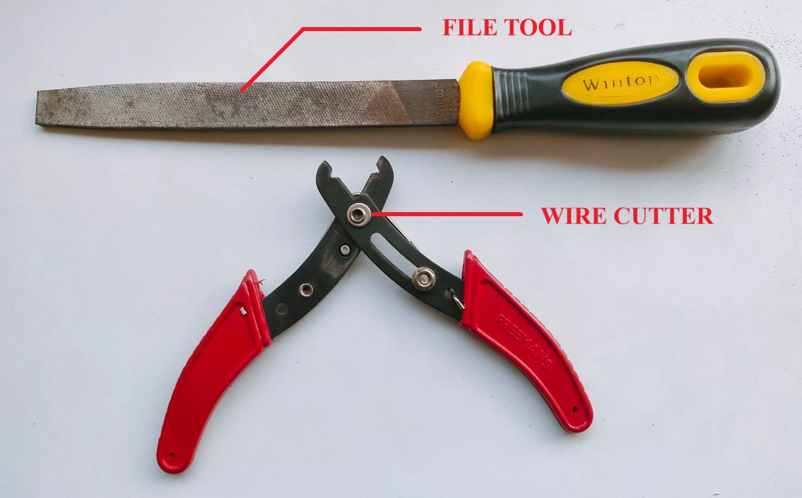
- The outer surface of the breakout board was not proper, so I used a wire cutter to cut the unwanted pieces and the file tool to file the edges of the PCB.
- The photo given below illustrates the breakout board with all the required components.
- The solder paste was applied to the breakout board using a stencil, and the components were placed in their positions.
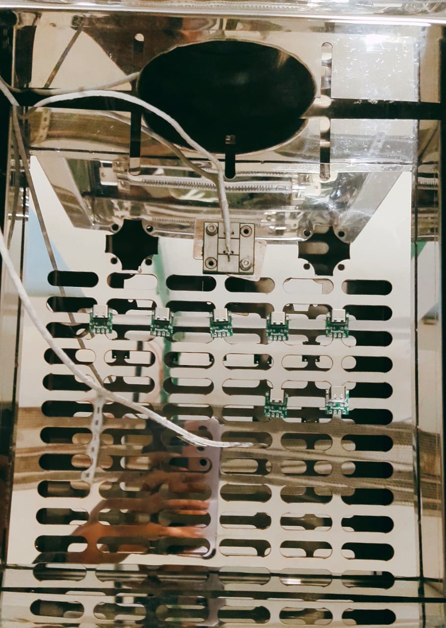
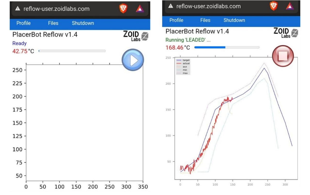
- The PCB was then placed in the oven to perform the reflow.
- To operate the oven, Turn on the wifi, then connect to Reflow-0001.
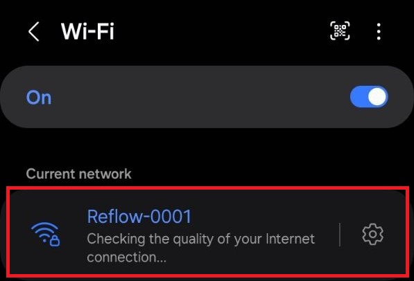
- A new site “reflow-user.zoidlabs.com” will open up automatically.
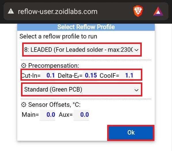
- We selected “Leaded( for leaded solder-max:230C” from “select a reflow profile to run” drop down list.
- From the precompensation drop down list we selected “standard(green PCB)”.
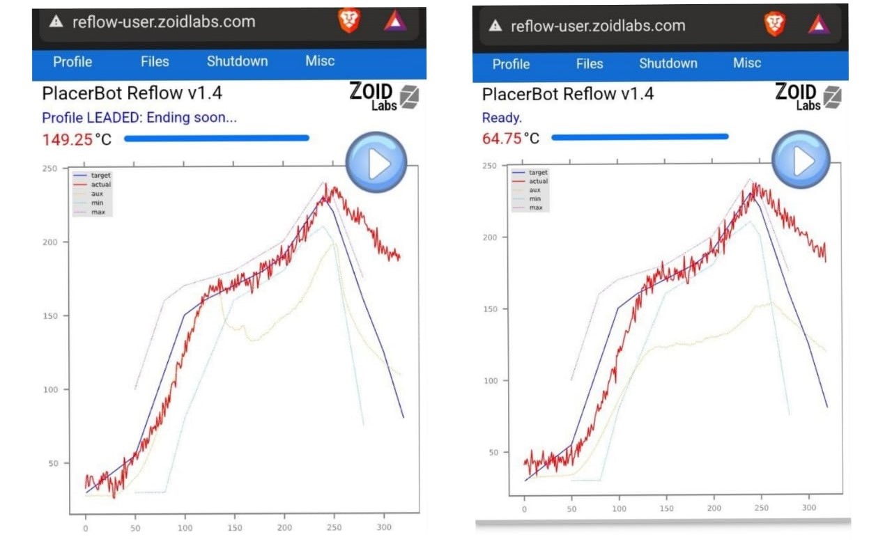
- The photo below shows the graph of the reflow temperature in degree Celsius.
- After performing the reflow soldering, I used a Lynx EVO Stereo Microscope to check the connections and found a few pins were short.
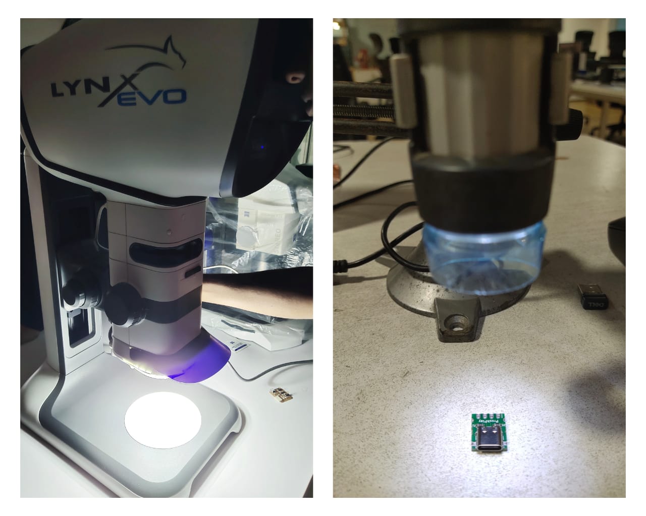
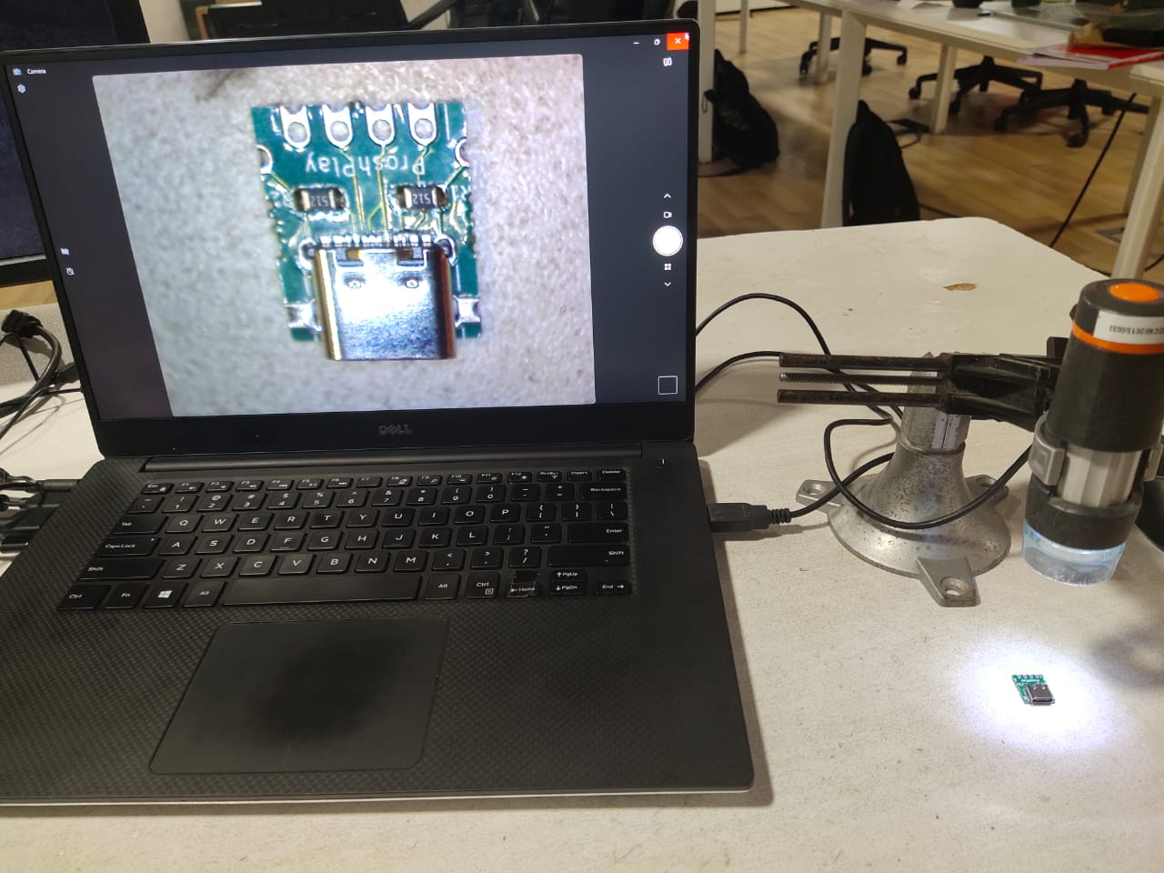
- With the help of a soldering wick, the excess lead is removed, and the pins are checked using a portable digital microscope.
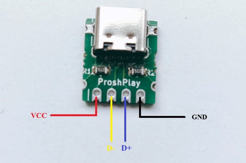
- The photo below illustrates the pinout diagram of the type C breakout board.
Reference
Resources and Downloads
📁 Code