Professor Neil's lecture on Wednesday kicks off this week. The following day, our instructor, Mr. Mufeed, together with Mr. Ravi went over all of the important terms and conditions for this week. I gained knowledge of the various kinds of molding and casting, the materials needed for them, and the safety measures to be taken when doing them.
Molding
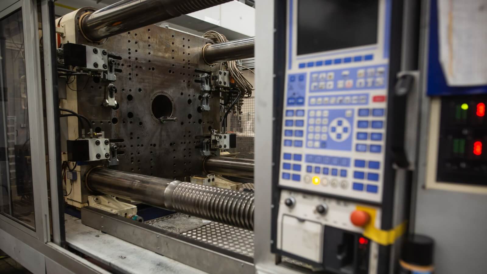
Molding refers to the process of shaping a material, typically a soft or semi-liquid substance, into a specific form or shape using a mold. The material could be anything from plastic and metal to glass and ceramics. The molding process can be achieved through various techniques, such as injection molding, compression molding, blow molding, and rotational molding.
⬇️
Follow the link below to know more about molding, types, materials, and application.
This is one of the most widely used molding processes for producing plastic parts. Molten plastic is injected into a mold under high pressure. Once the plastic cools and solidifies, the mold opens, and the finished part is ejected.
Blow Molding
Primarily used for producing hollow plastic parts, such as bottles and containers. A tube of molten plastic, called a parison, is extruded and then inflated inside a mold to take its shape.
Compression Molding
Commonly used for thermosetting plastics and rubber materials. The material is placed into a heated mold cavity and compressed between two heated mold halves to form the desired shape.
Rotational Molding
Used to create hollow parts by rotating a mold filled with powdered plastic resin. The rotating action evenly distributes the resin inside the mold, which then melts and coats the inner surface of the mold as it heats.
Extrusion Molding
A continuous process where a material, often plastic, is forced through a die to produce a long, continuous shape, such as tubes or profiles. The extruded shape is then cooled and cut to the desired length.
Thermoforming
Involves heating a sheet of thermoplastic material until it becomes pliable. The heated sheet is then stretched over or into a mold and cooled to form the desired shape.
Casting
Involves pouring a liquid material, such as metal or resin, into a mold. Once the material solidifies, the mold is removed, leaving behind the cast object.
Die Casting
A metal casting process that uses a mold, called a die, into which molten metal is injected under high pressure. Commonly used for producing metal parts with high accuracy and surface finish.
Materials Used for Molding
Plastics
Thermoplastics: These are plastics that can be melted and re-molded multiple times without significant degradation. Examples include polyethylene (PE), polypropylene (PP), polystyrene (PS), and polyvinyl chloride (PVC).
Thermosetting Plastics: These plastics undergo a chemical reaction during molding, becoming permanently set. Examples include epoxy resins, phenolic resins, and melamine resins.
Rubbers
Natural Rubber: Derived from the latex sap of rubber trees, it offers good elasticity and resilience.
Synthetic Rubbers: These include materials like silicone rubber, neoprene, nitrile rubber, and EPDM (ethylene propylene diene monomer), each offering unique properties such as high temperature resistance, oil resistance, or weather resistance.
Metals
Aluminum: Lightweight and corrosion-resistant, often used in die casting and injection molding processes.
Steel: Durable and strong, commonly used in injection molding molds due to its hardness and wear resistance.
Zinc, Magnesium, and Copper Alloys: Used in die casting processes to produce parts with high strength and dimensional accuracy.
Ceramics
Porcelain: A type of ceramic material known for its high strength, hardness, and heat resistance. Used in molding processes for producing electrical insulators, dental prosthetics, and decorative items.
Alumina and Zirconia: High-performance ceramics used in specialized molding applications requiring extreme hardness, wear resistance, and thermal stability.
Composites
Fiber-Reinforced Polymers (FRP): These are composite materials made of a polymer matrix reinforced with fibers such as fiberglass, carbon fiber, or aramid. They offer high strength-to-weight ratio and are used in molding processes to produce lightweight and durable parts.
Foams
Polyurethane Foam: A versatile material used in molding to produce lightweight, cushioning, and insulating products such as seat cushions, mattresses, and thermal insulation panels.
Polystyrene Foam: Commonly used in injection molding to produce foam products like packaging materials and insulation boards.
Glass
Borosilicate Glass: Known for its high thermal resistance and chemical inertness, used in specialized molding processes to produce laboratory glassware, lighting components, and optical lenses.
Silicone Molding
Silicone molding, also known as silicone rubber molding, is a type of molding process that uses silicone rubber as the molding material. This method is widely used for creating flexible and durable parts, often for prototypes, low-volume production, and intricate designs that are difficult to achieve with other molding processes.
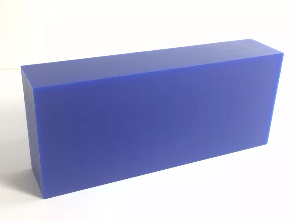
Machinable Wax
Machinable wax, also known as modeling wax or pattern wax, is a specialized type of wax used in prototyping, modeling, and mold-making applications. It is formulated to exhibit properties that make it easy to machine, carve, or shape using conventional machining tools, such as milling machines, lathes, and CNC routers. Machinable wax allows for the creation of intricate and precise prototypes or molds without the need for specialized tooling or equipment.
⬇️
Follow the link below to learn more about the technical data of the machinable wax.
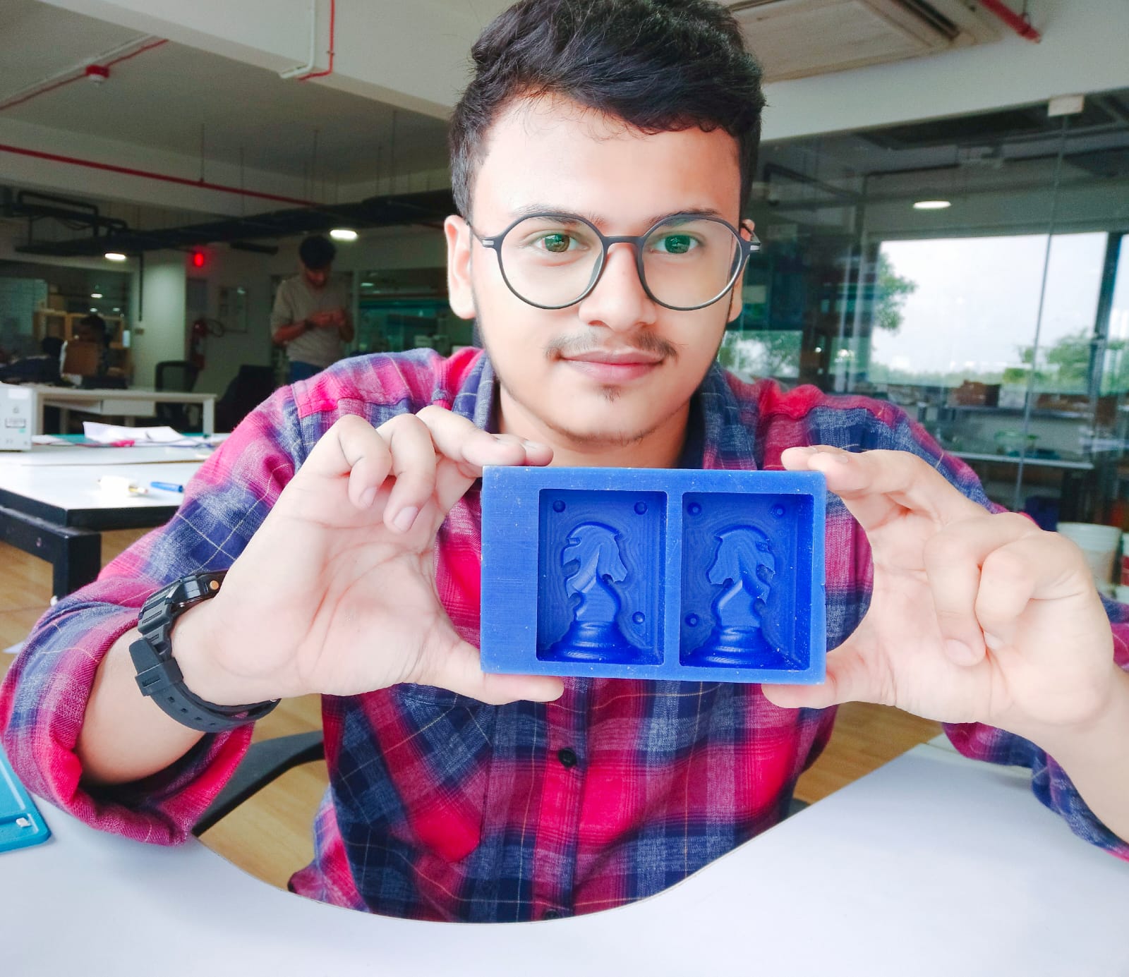
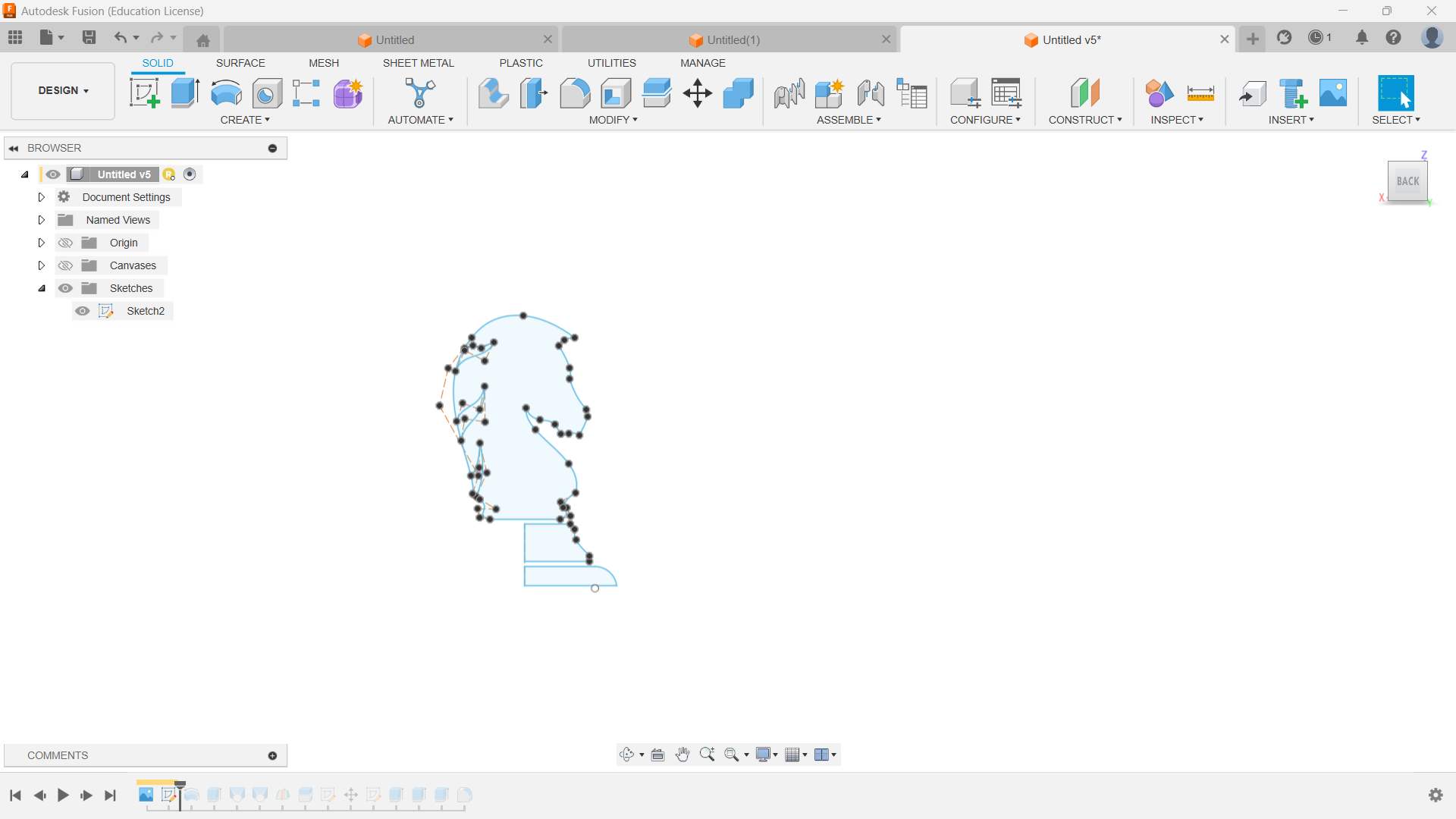
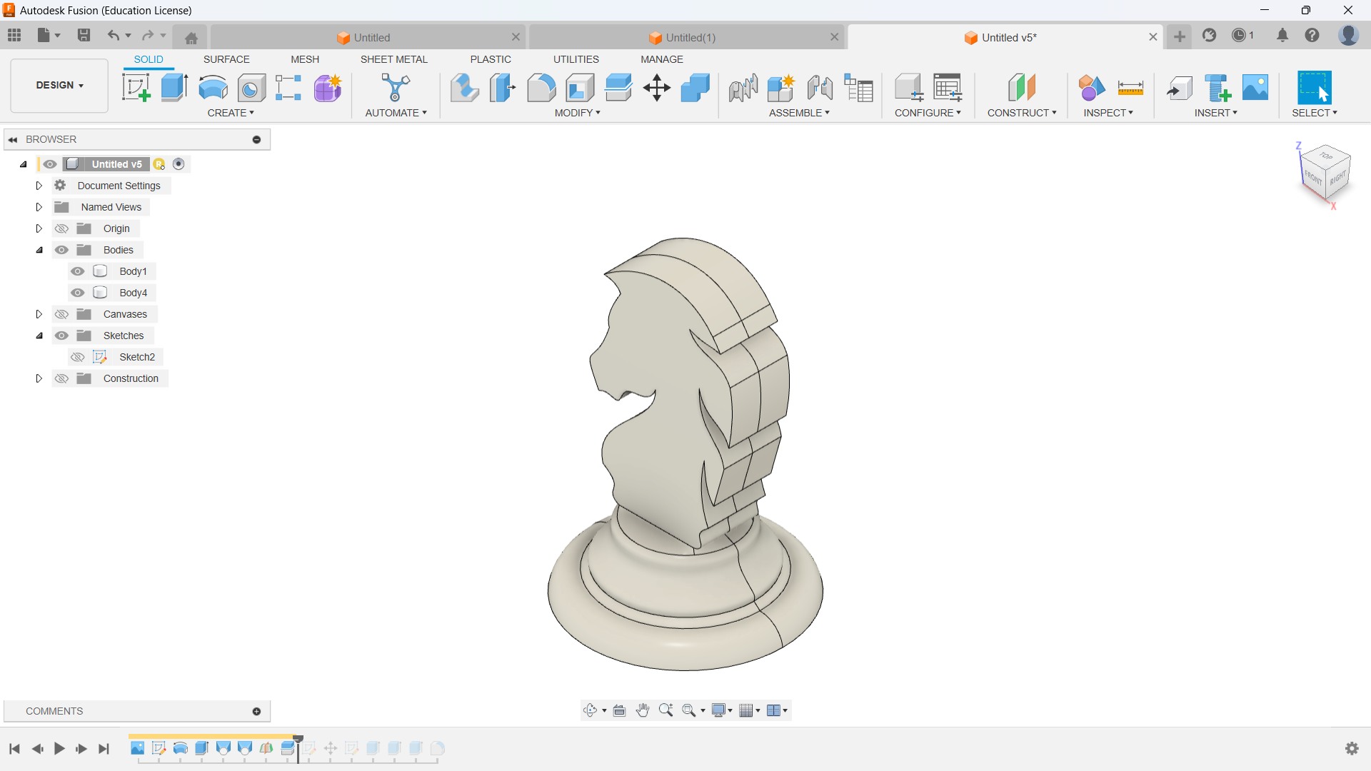
This week, I chose to cast a chess piece that would be useful for my final project as well, and I chose the knight because it is the most challenging part among other chess pieces. I started to design the sketch in Fusion 360.
⚠️
Always keep in mind the minimum diameter of the end mill available in our fab lab while designing the model.
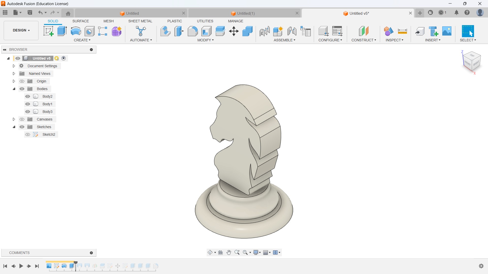
Later, I converted the sketch into 3D by extruding and revolving the sketch.
🚨
The first step in casting my piece is to create a positive part to create a negative mold. Compared to other chess pieces, I need to create a negative part for the knight because the other part is the mirror of the first part.
🚨
I created a mid-plane and split the body into two pieces.
🚨
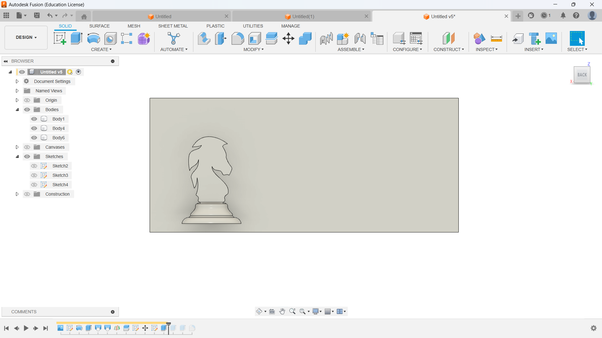
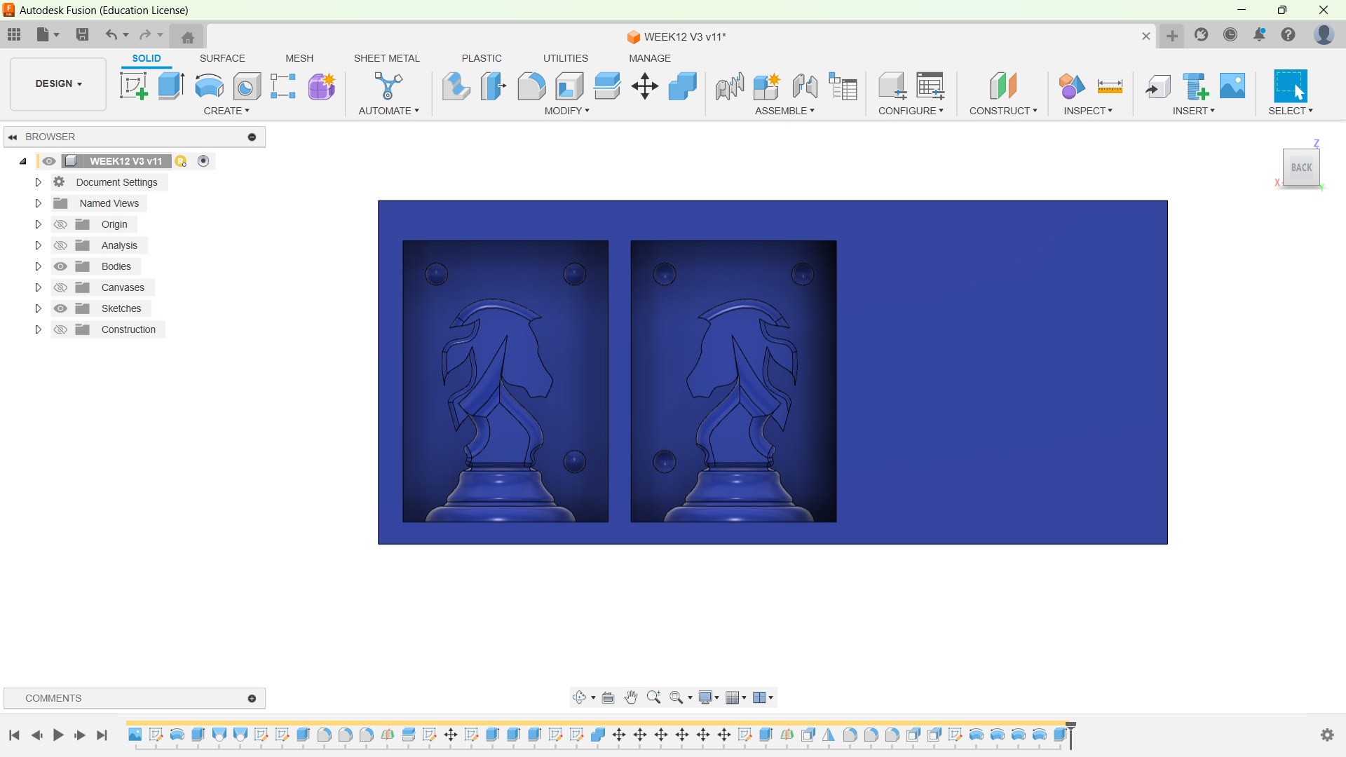
In order to get a visual representation of how my piece would be placed in the machinable wax, I created a block with the exact dimensions of the machinable wax.
🚨
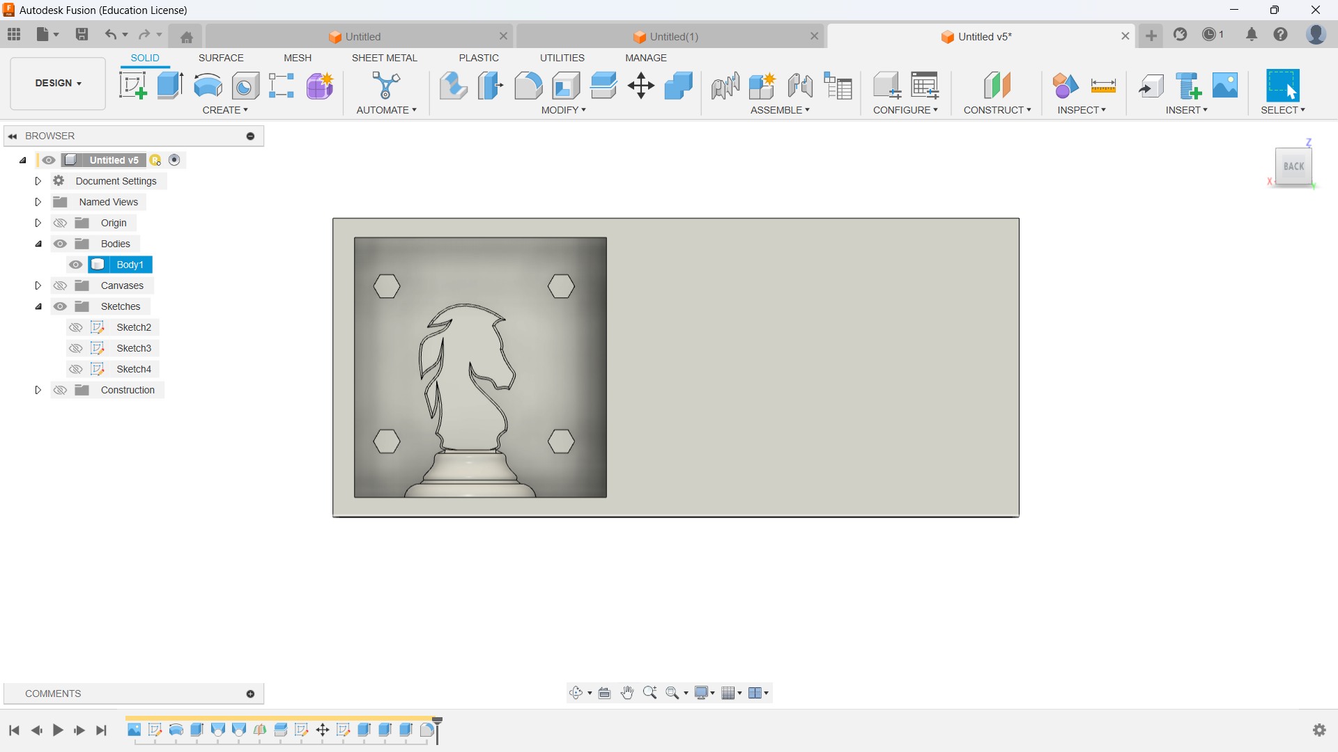
The image below illustrates the positive part of the piece used to cast the mold for the chess piece.
🚨
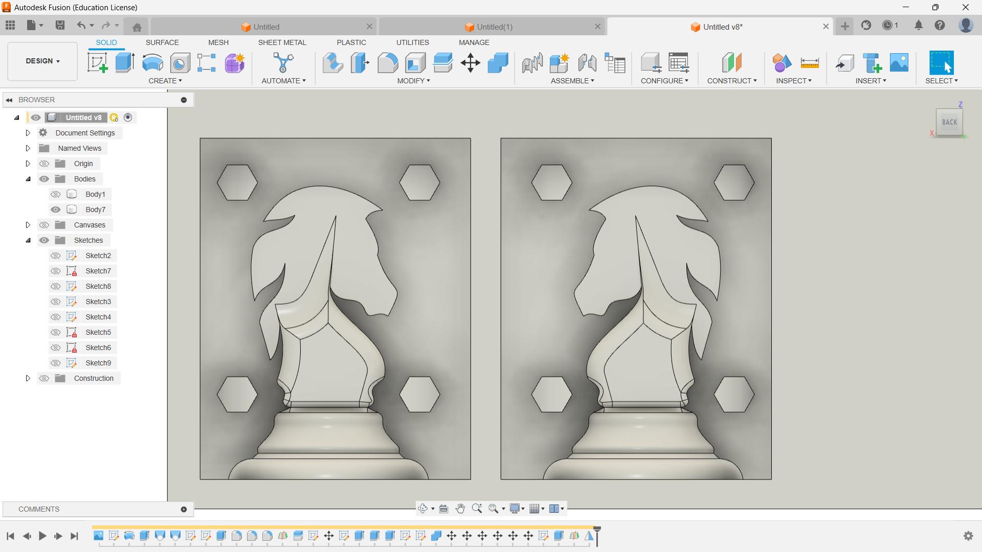
Later, I mirrored the features to replicate the mirrored part. I added the hexagonal part to place the two parts properly. My initial idea was to 3D print the hexagonal connector inside the two mold.
🚨
Later, I realised it was a rubbish idea. Instead of creating the hexagonal rod, I just needed to place a few hemispheres.
🚨
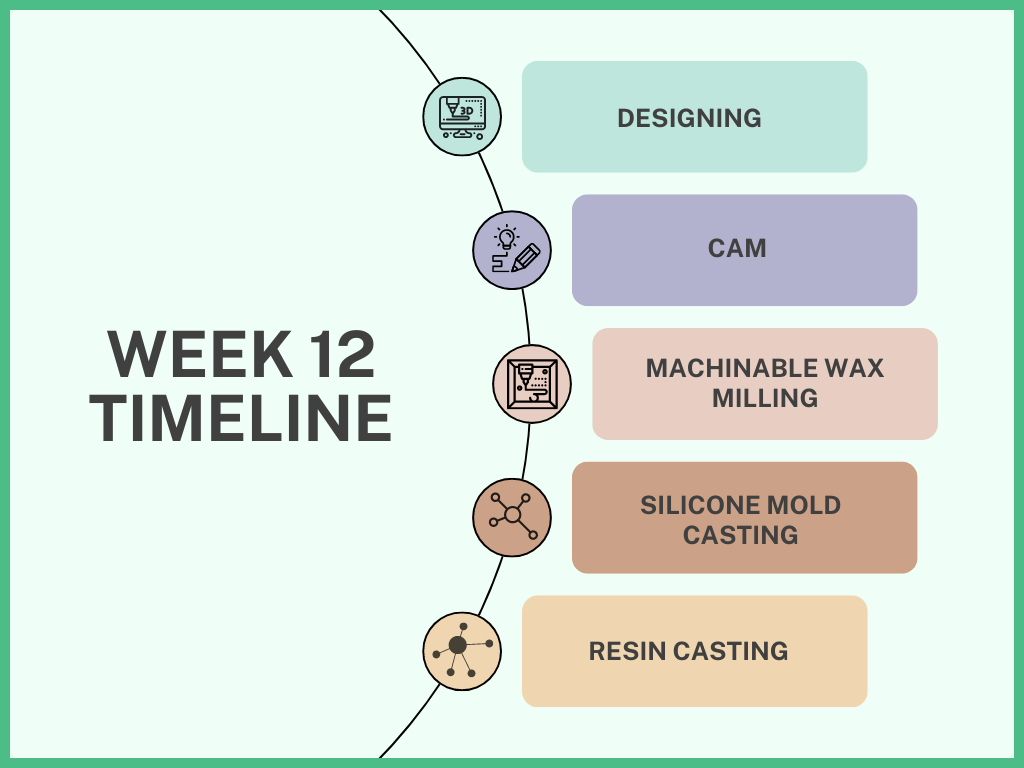
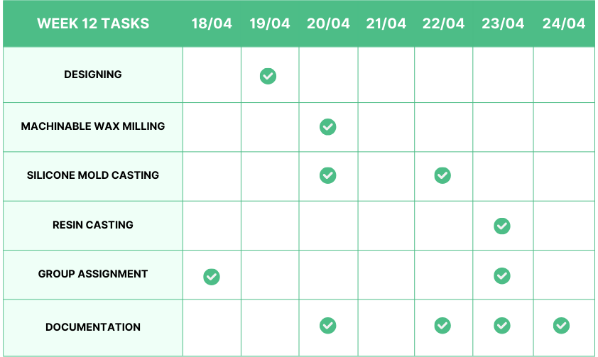
The design timeline is presented below.
🚨
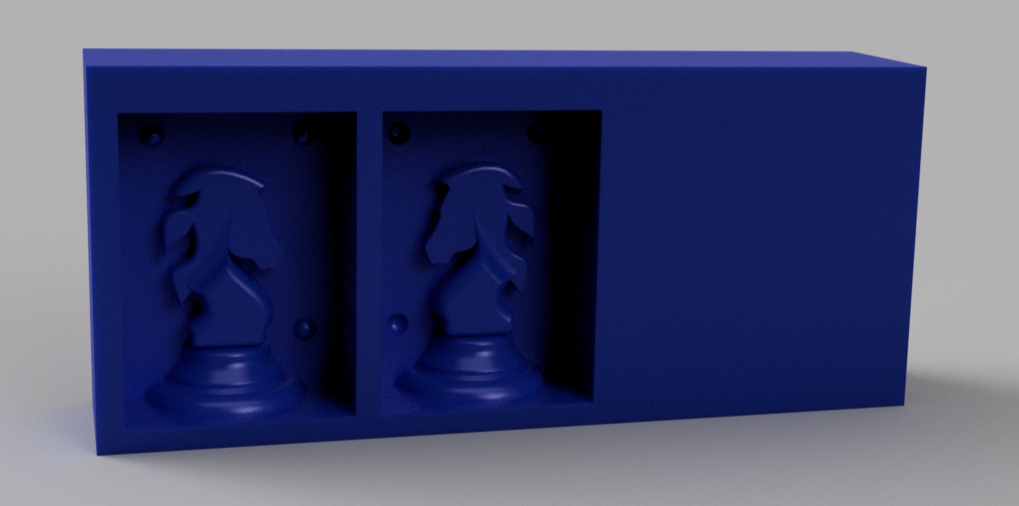
The image below illustrates the rendered view of the mold for the actual mold.
🚨
The design file is embedded below.
Computer-Aided Manufacturing
Computer-aided manufacturing (CAM) isa technology that uses computer software and machinery to automate and speed up the production of goods. CAM helps improve accuracy, reduce waste, and increase productivity.
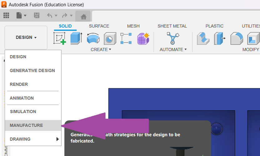
In order to perform CAM in Fusion 360, we need to change the workspace from the design to the manufacturing workspace.
Tool Library
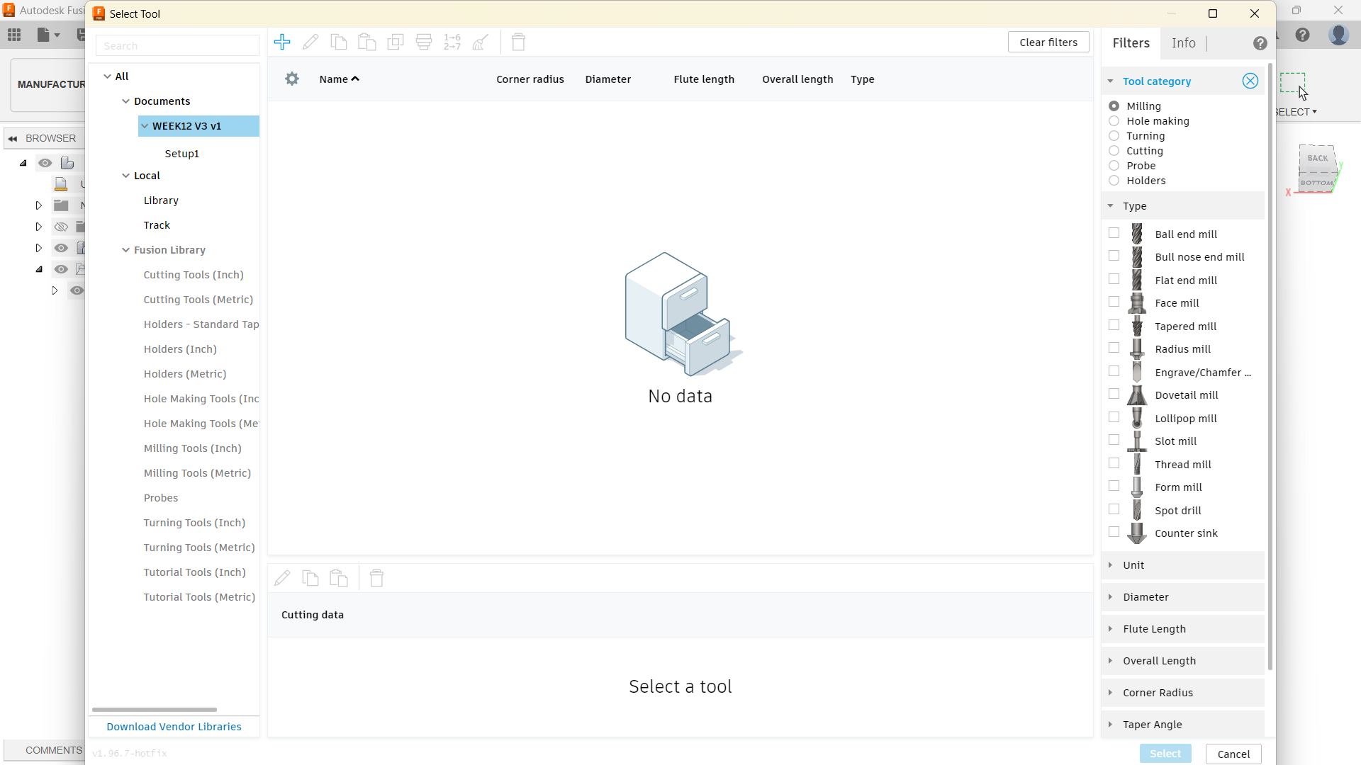
The Tool Library in Autodesk Fusion 360 allows users to store and organize CNC and CAM cutting tools. It includes nearly 8,000 tools, such as keyseat cutters and undercutting end mills.
🚨
The Tool Library is divided into three sections, including tool libraries, libraries of predefined tools, and project documents.
🚨
We can also create custom libraries, and create and copy tools and holders. With each tool, we can associate multiple Cutting Data parameters (feeds and speeds).s
Import Tool Library
🚨
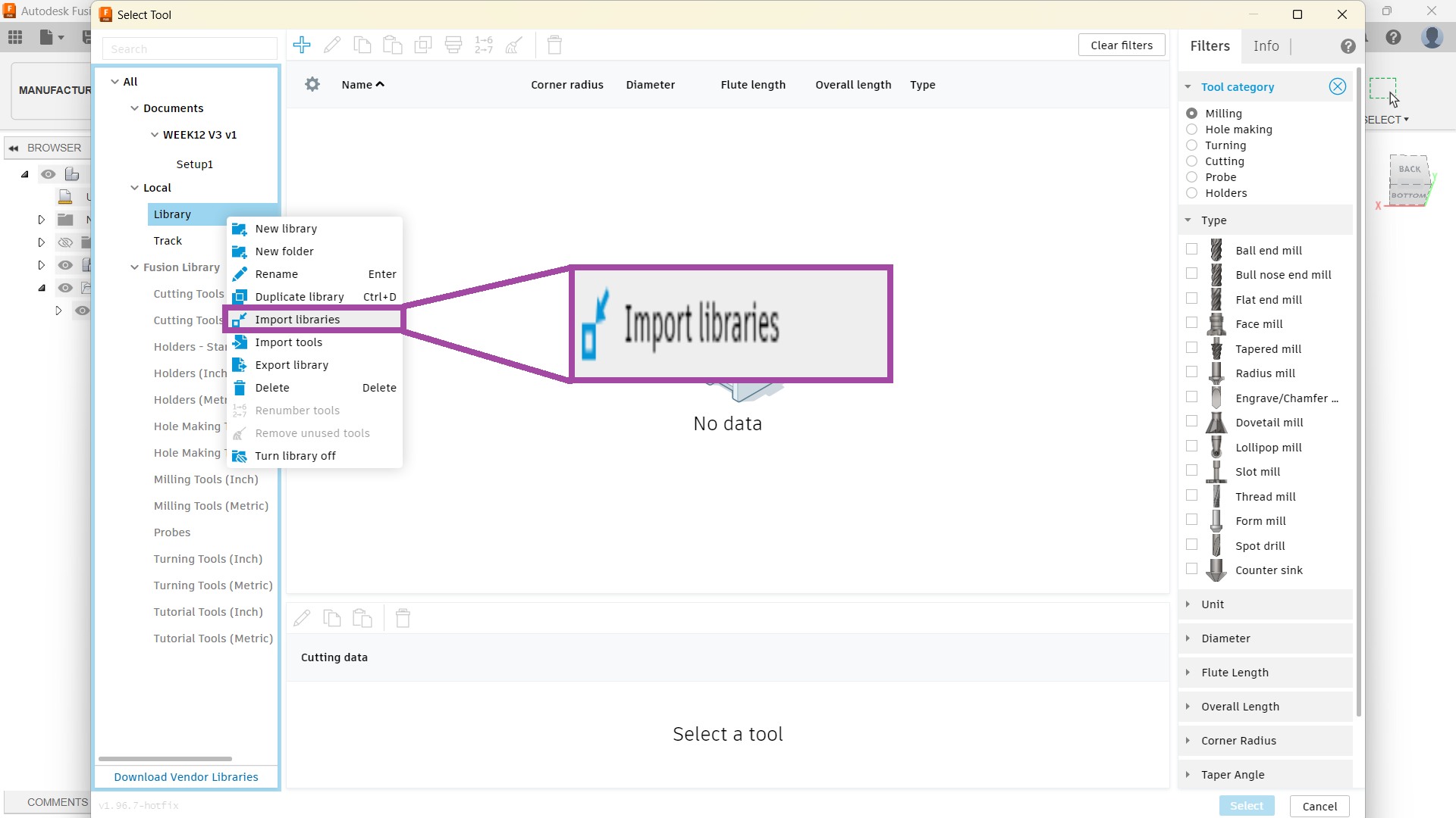
Since I am using the CAM for the first time in Fusion 360, I need to add the tools to my library. My instructor shared a tool library with the tools available in our lab.
🚨
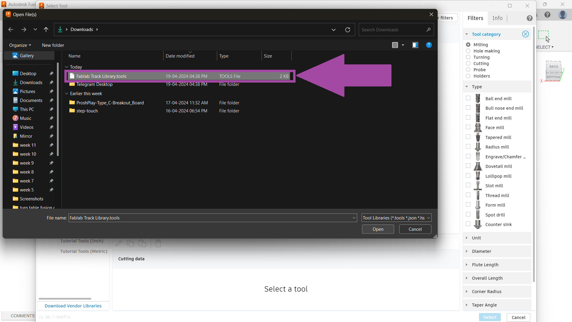
The tool library I used is provided in the downloads and resources section.
🚨
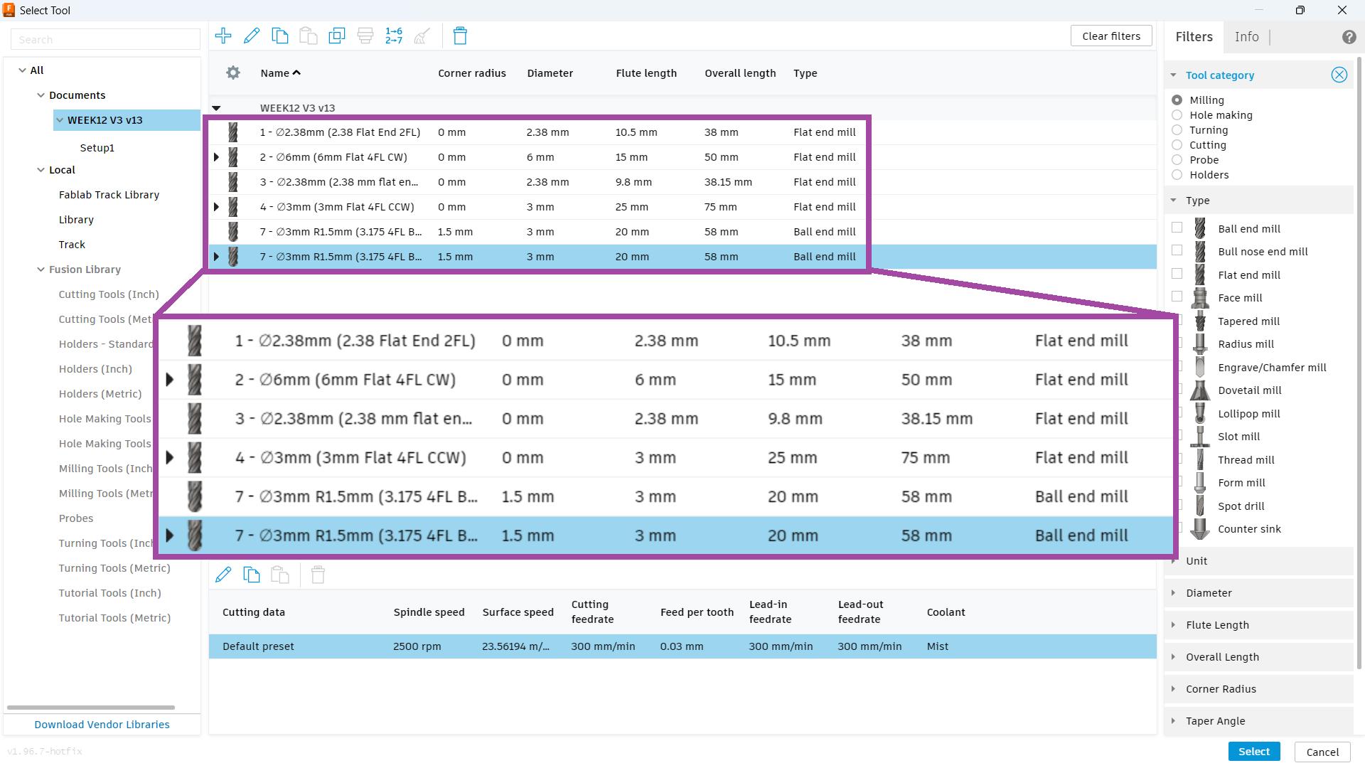
Right-click the “Library” and click on the “Import Library” option to open the tool library.
🚨
The image below illustrates the list of tools used in the tool library that I have imported.
Adding New Tools
🚨
I utilised our system to search for the accessible tools, and then I took precise measurements of their dimensions with a digital Vernier calliper. To make sure the tool information was current and matched the real tools we possessed, I uploaded these measurements to the tool library.
🚨
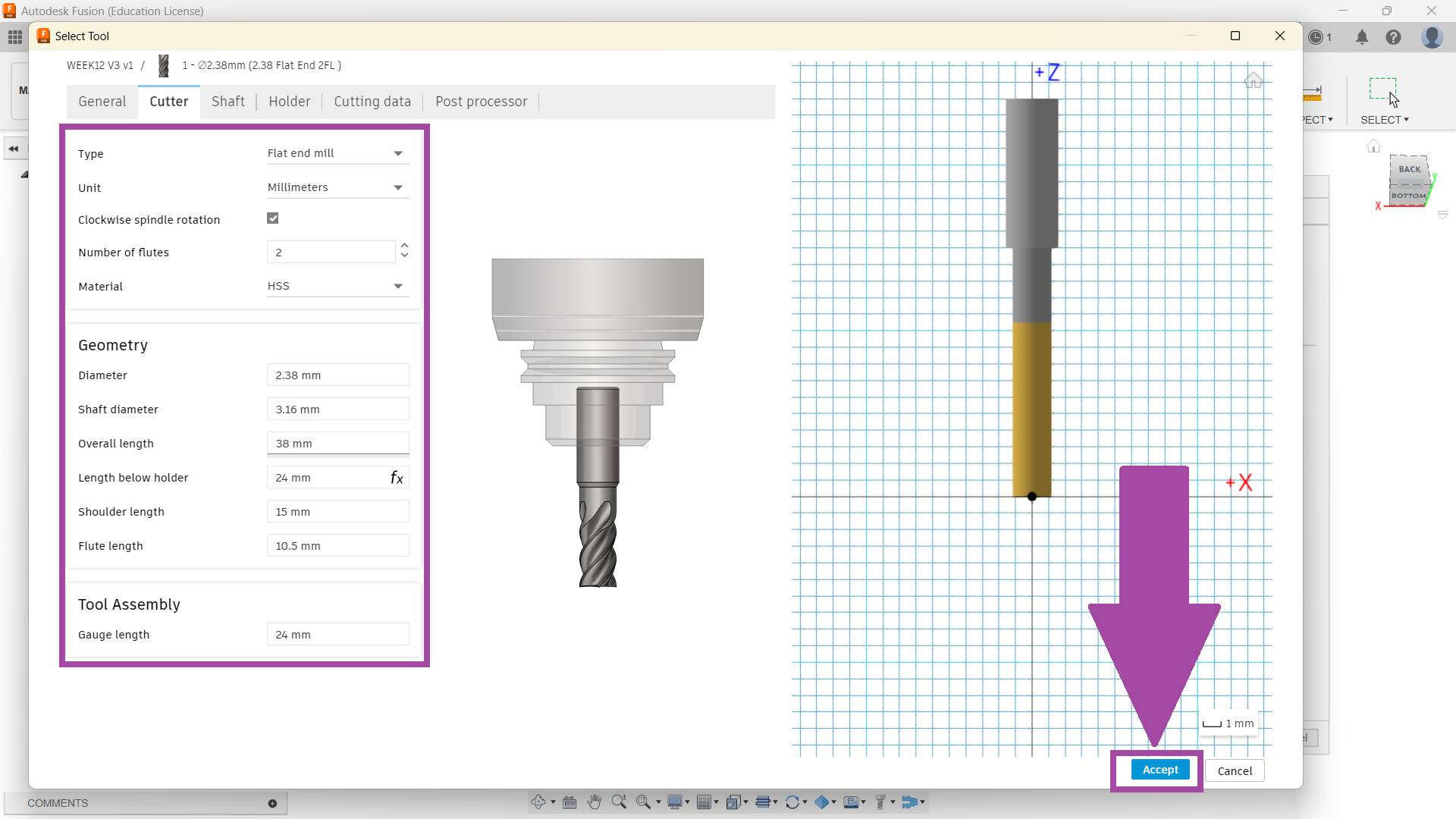
Select the plus icon to add a new tool to the library.
🚨
Add a brief description of the tool.
🚨
Select the “cutter” tab and fill in all the required values. Click on “Accept”.
Setting up the Setup
🚨
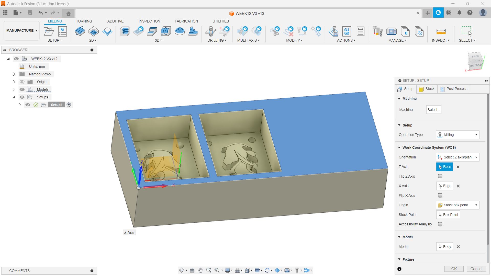
Click on “New Setup” from the setup panel.
🚨
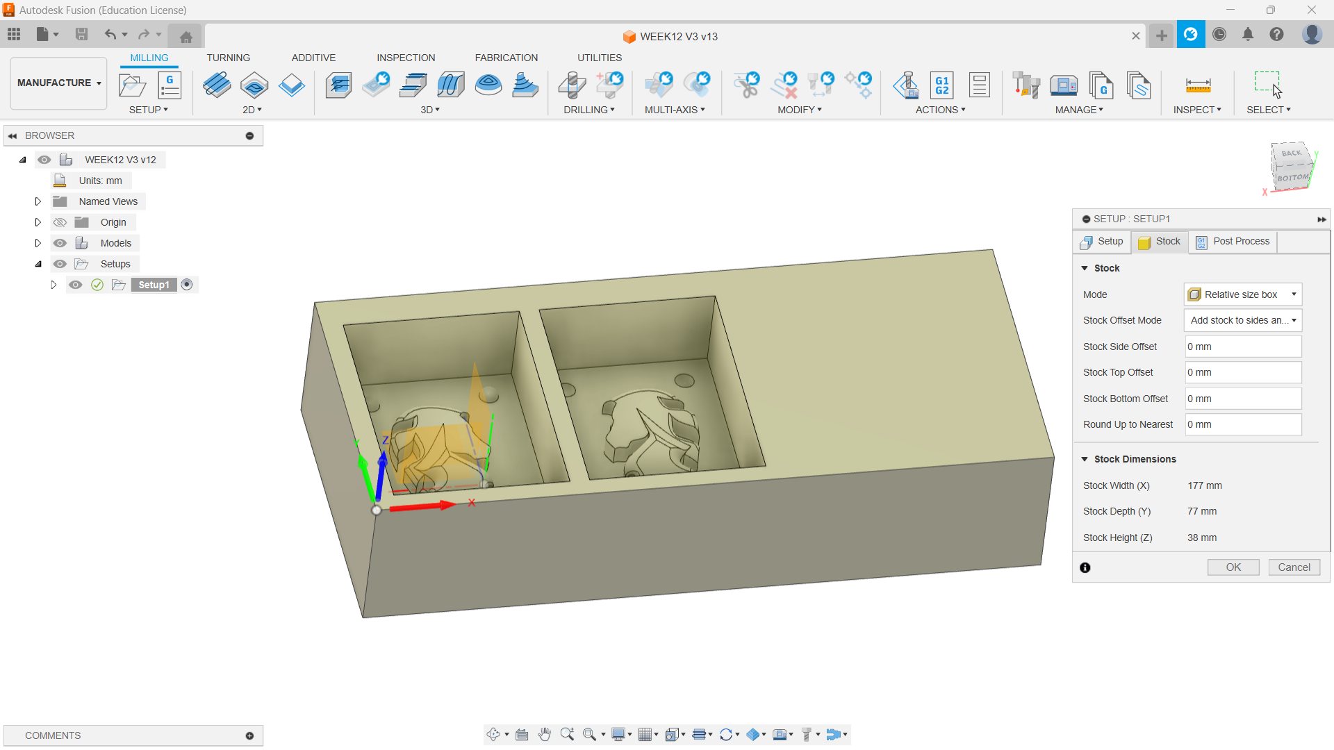
I selected the material and indicated the beginning in the upper corner. The milling operation type was selected. Since we had previously set up the stock on design with the same dimensions, we must declare the kind and dimensions of the material being used when setting up a new process.
🚨
Since I already know the workpiece's true dimensions, I decided not to use the offsets.
🚨
I want the x to face right, the z to face up, and the y to face left.
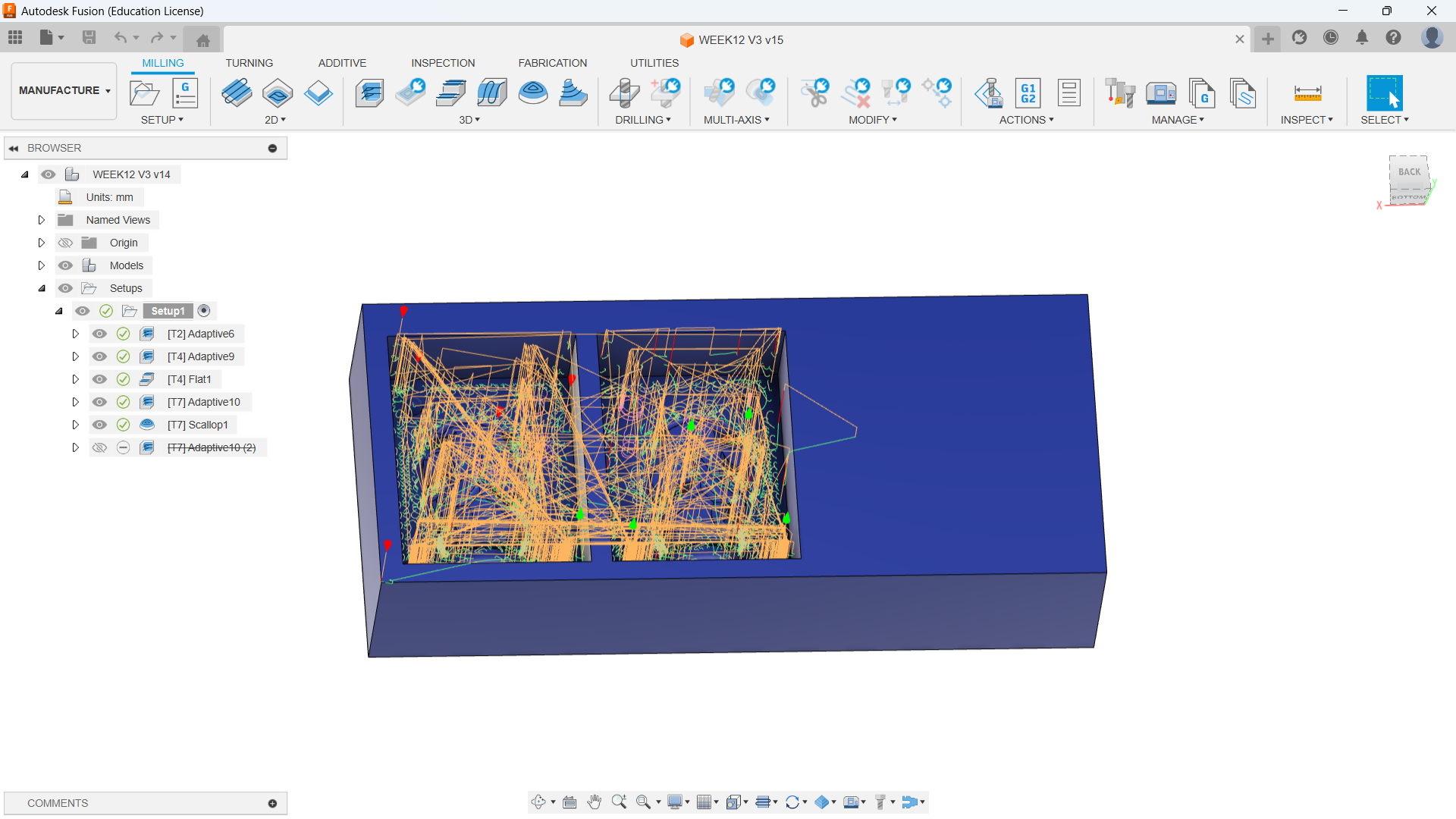
Milling Operation
Operation
Used Tool
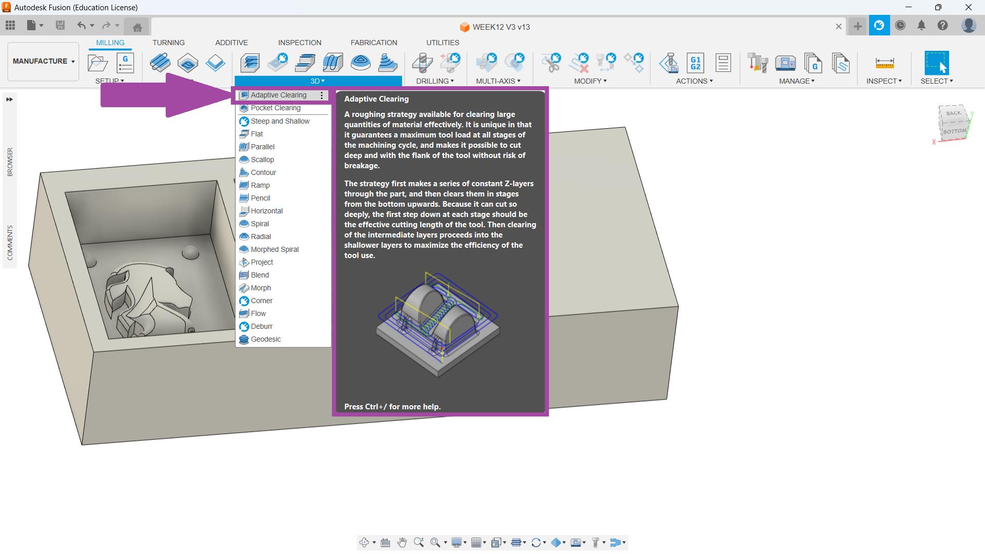
Adaptive
6 mm Flat
Adaptive
3 mm Flat
Flat
3 mm Flat
Adaptive
3 mm Ball
Scallop
3 mm Ball
Adaptive 6mm Flat
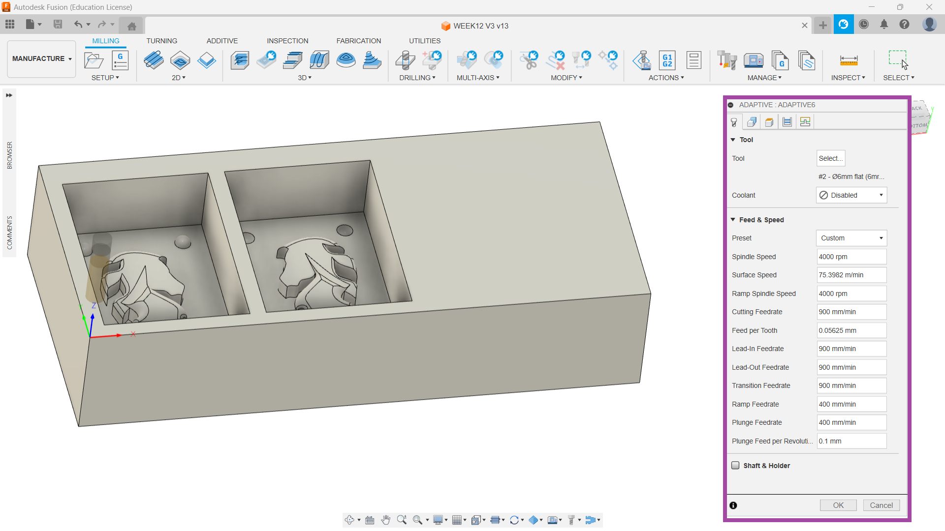
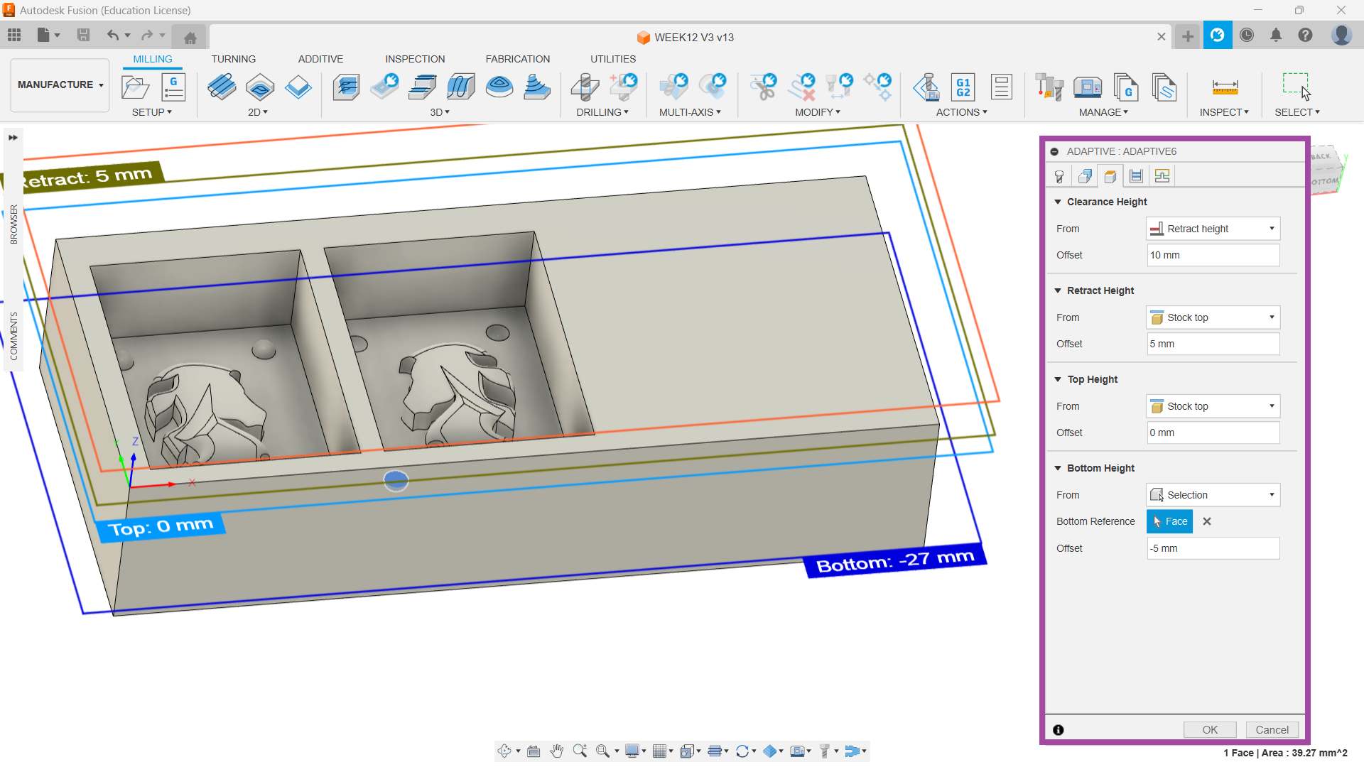
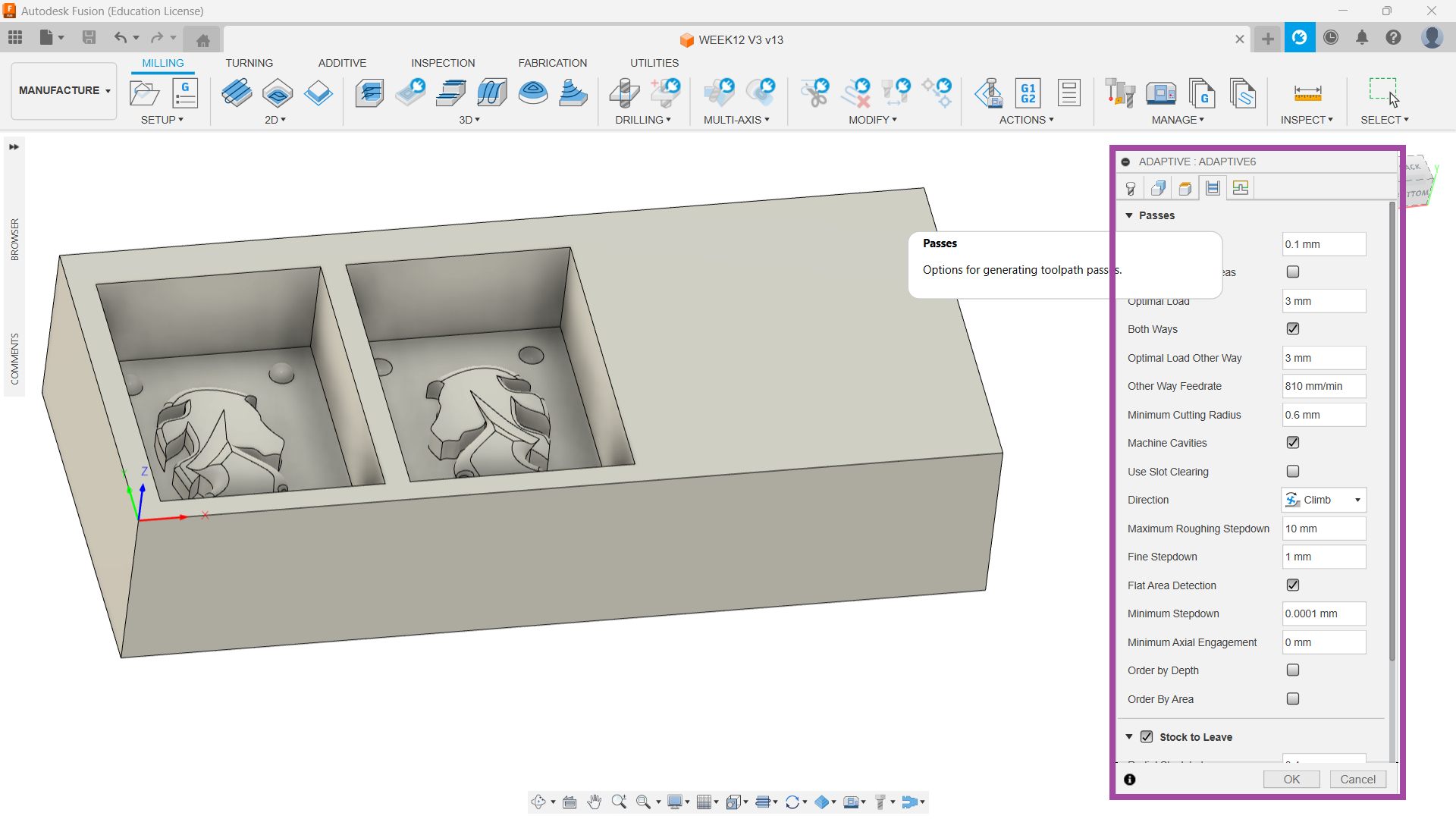
🚨
The first operation I chose was “Adaptive” and I selected the tool as a 6 mm flat end mill.
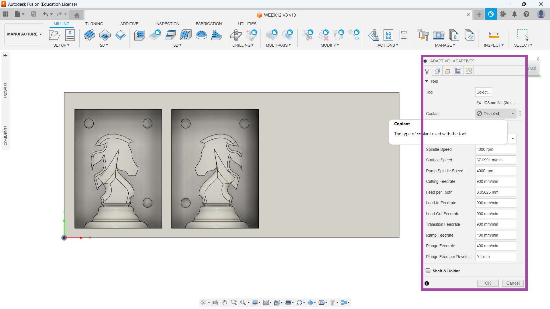
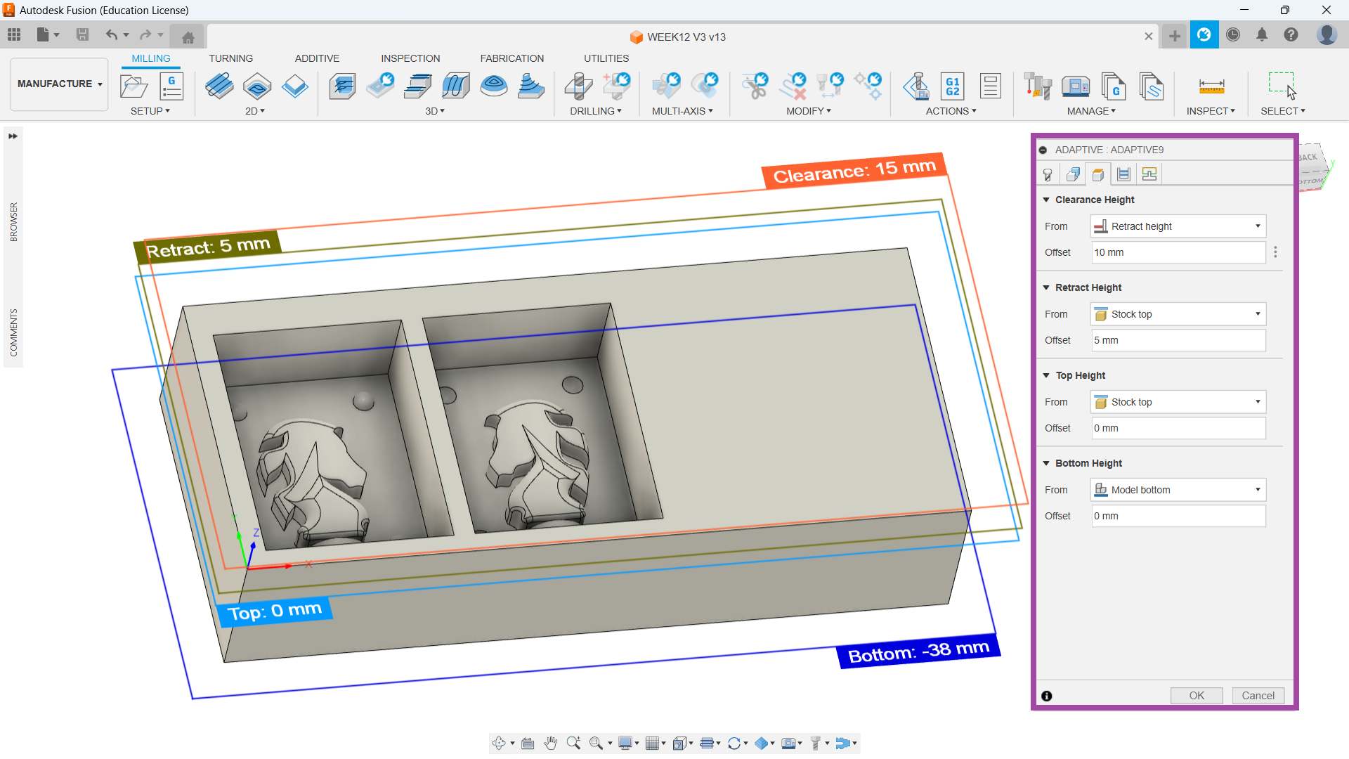
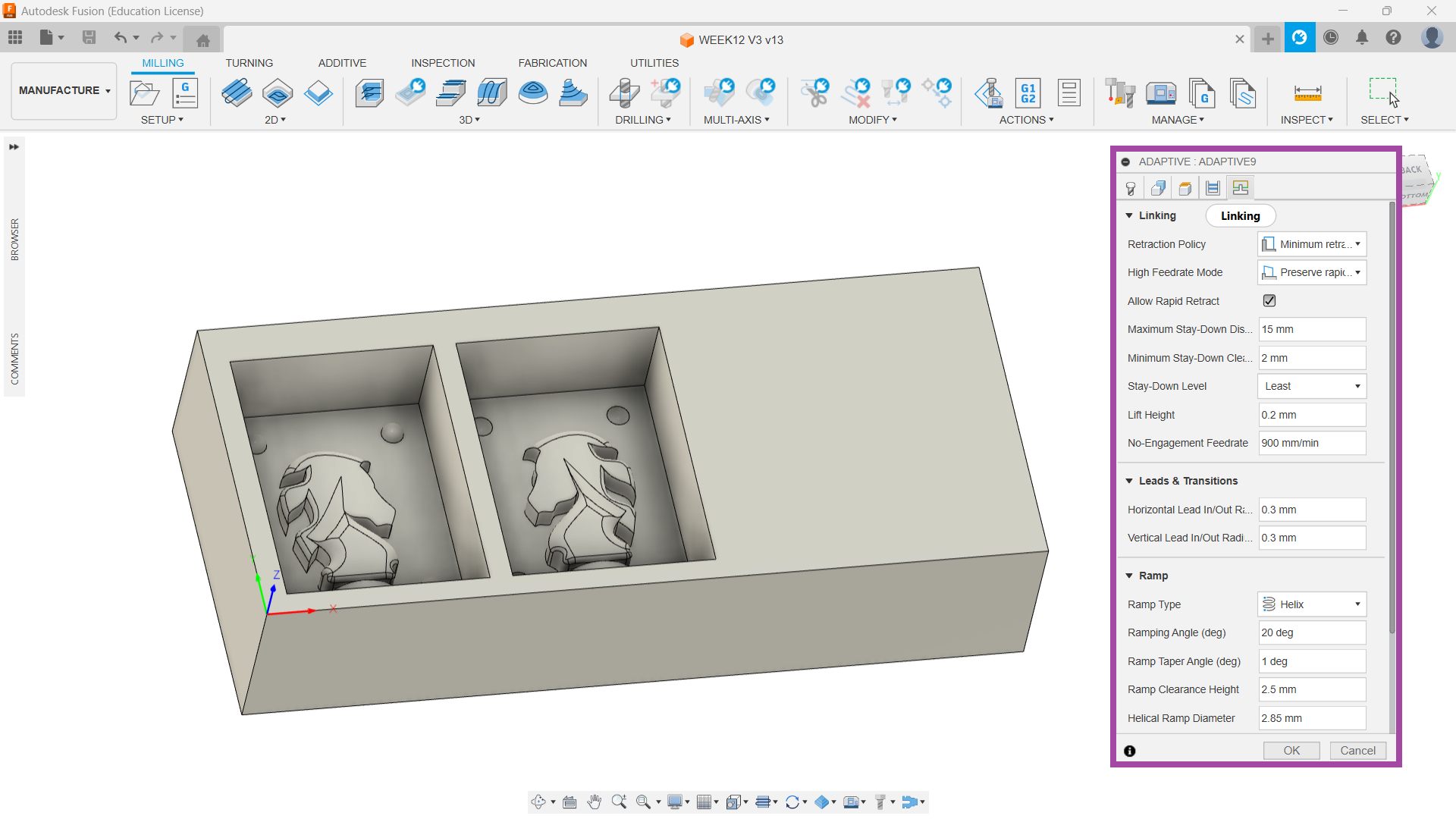
Adaptive 3 mm Flat
🚨
The second operation I chose was “Adaptive” and I selected the tool as a 3 mm flat end mill.
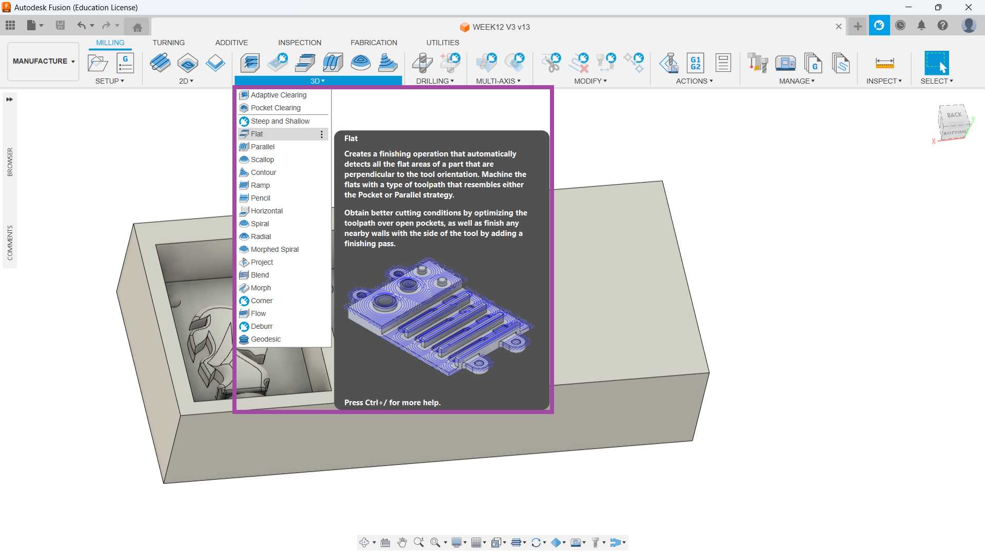
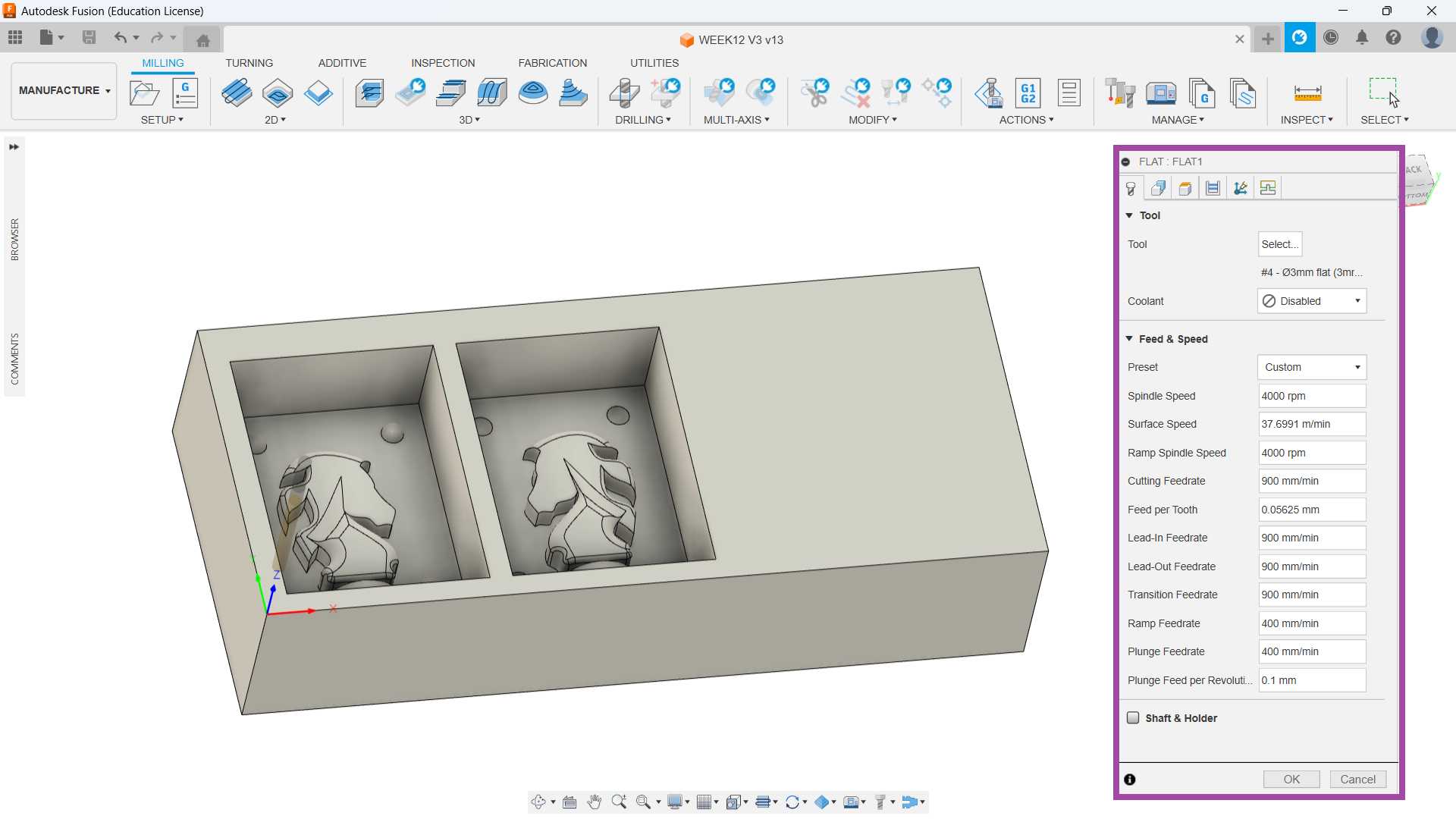
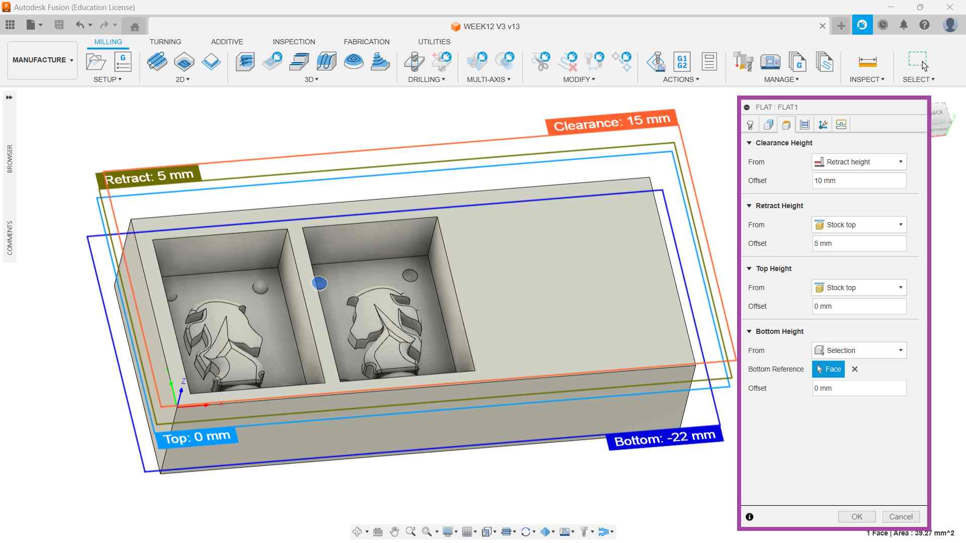
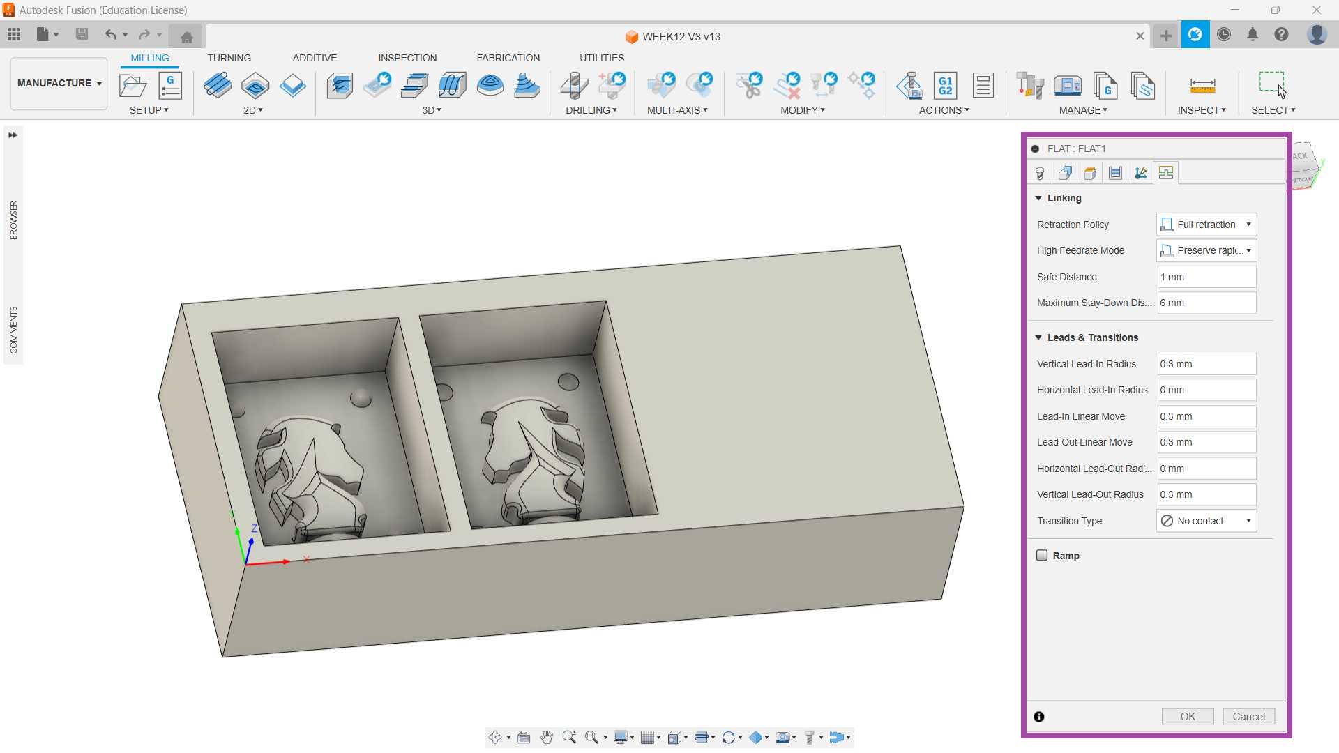
Flat with 3mm Flat
🚨
The third operation I chose was “Flat” and I selected the tool as a 3 mm flat end mill.
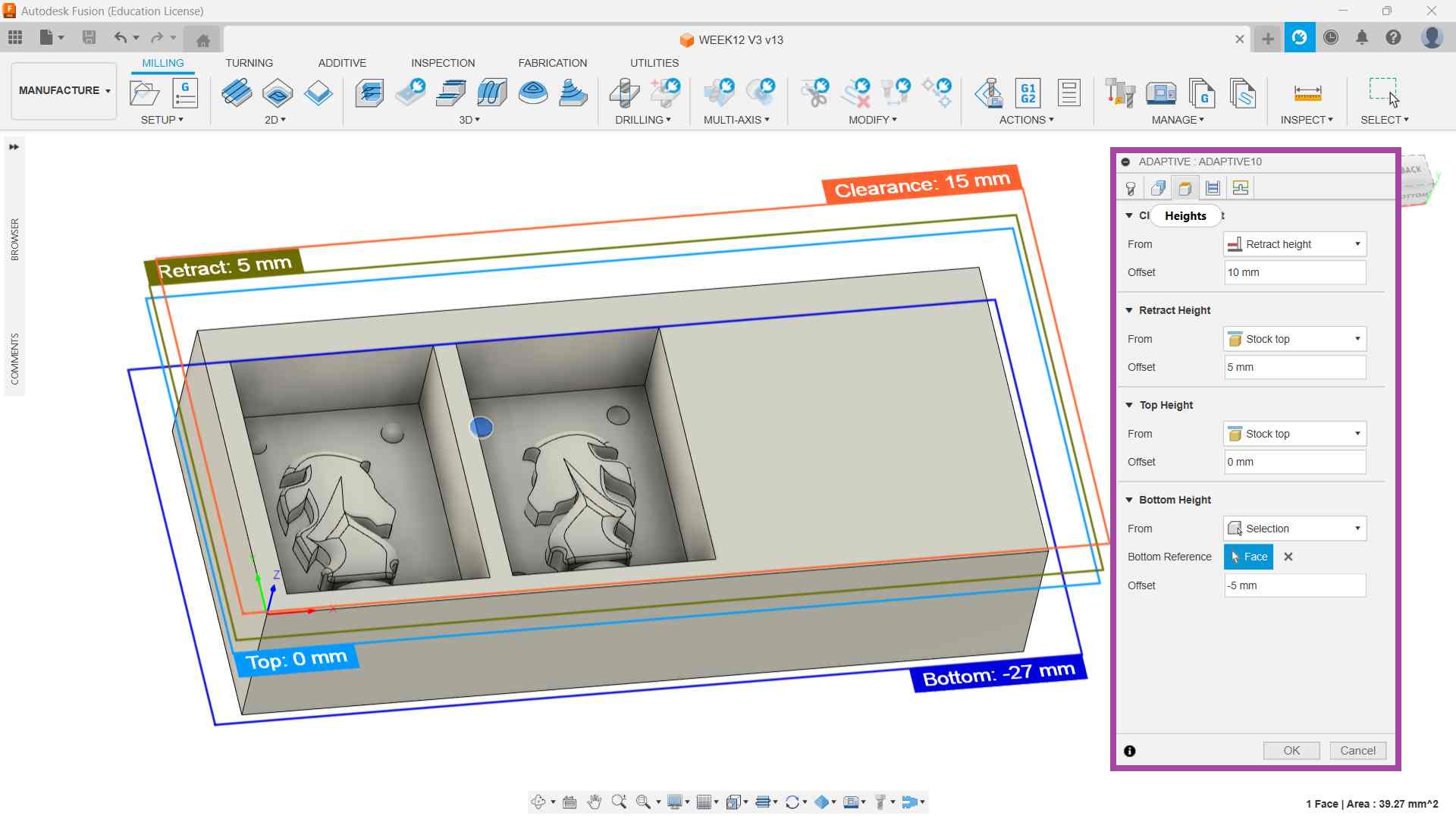
Adaptive 3mm Ball
🚨
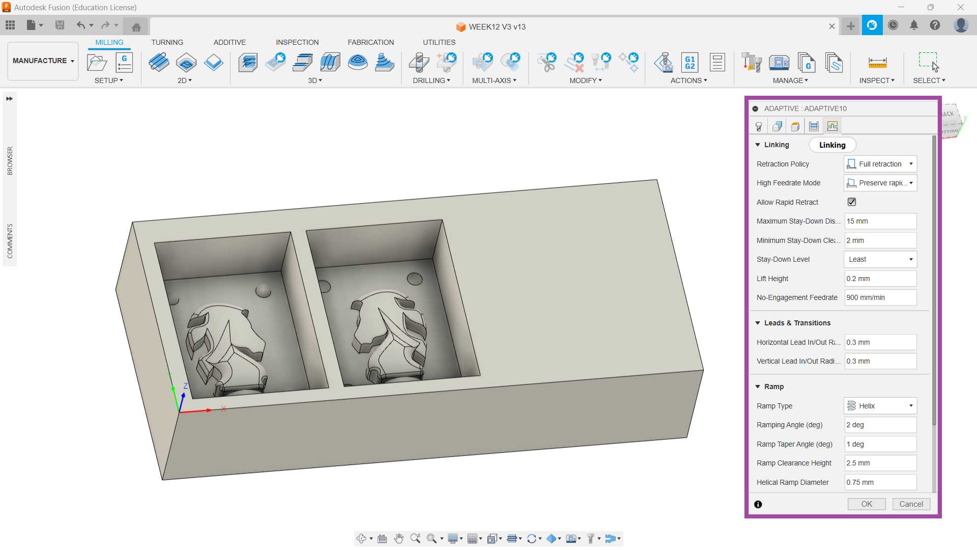
The fourth milling operation I chose was “Adaptive” and I selected the tool as a 3 mm ball end mill.
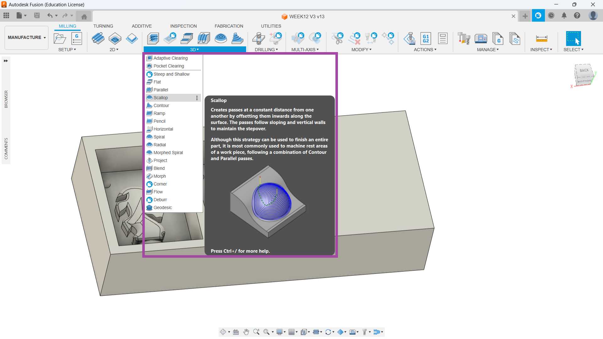
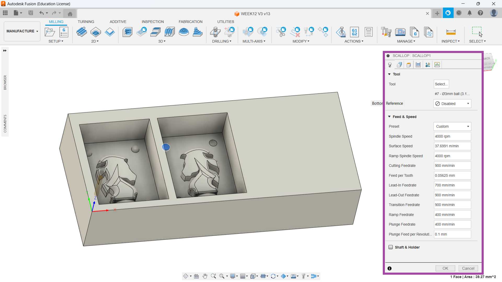
Scallop 3mm ball
🚨
The second operation I chose was “Scallop” and I selected the tool as a 3 mm ball end mill.
Toolpaths
Simulation
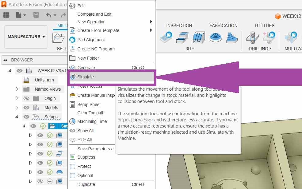
🚨
To simulate the CAM, right click the “setup” and select “Simulate”.
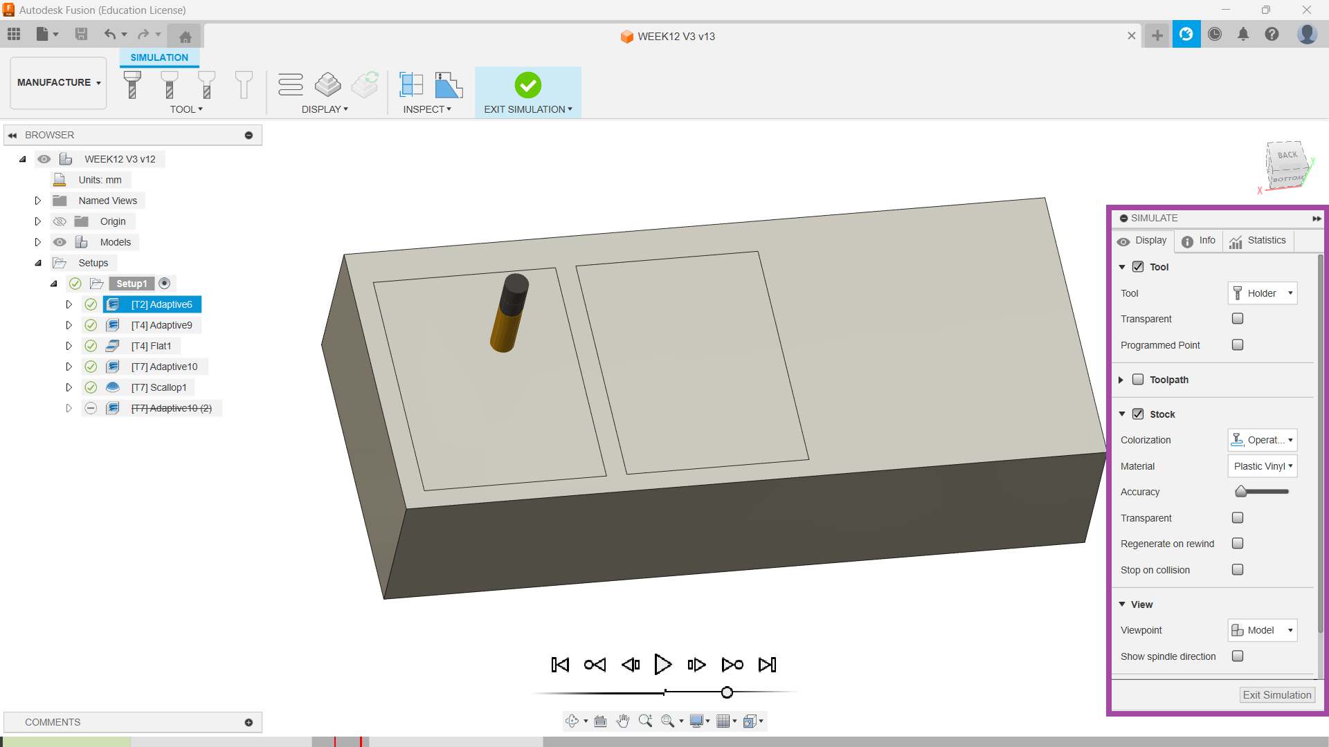
🚨
The image below illustrates the start of the simulation of the CAM process.
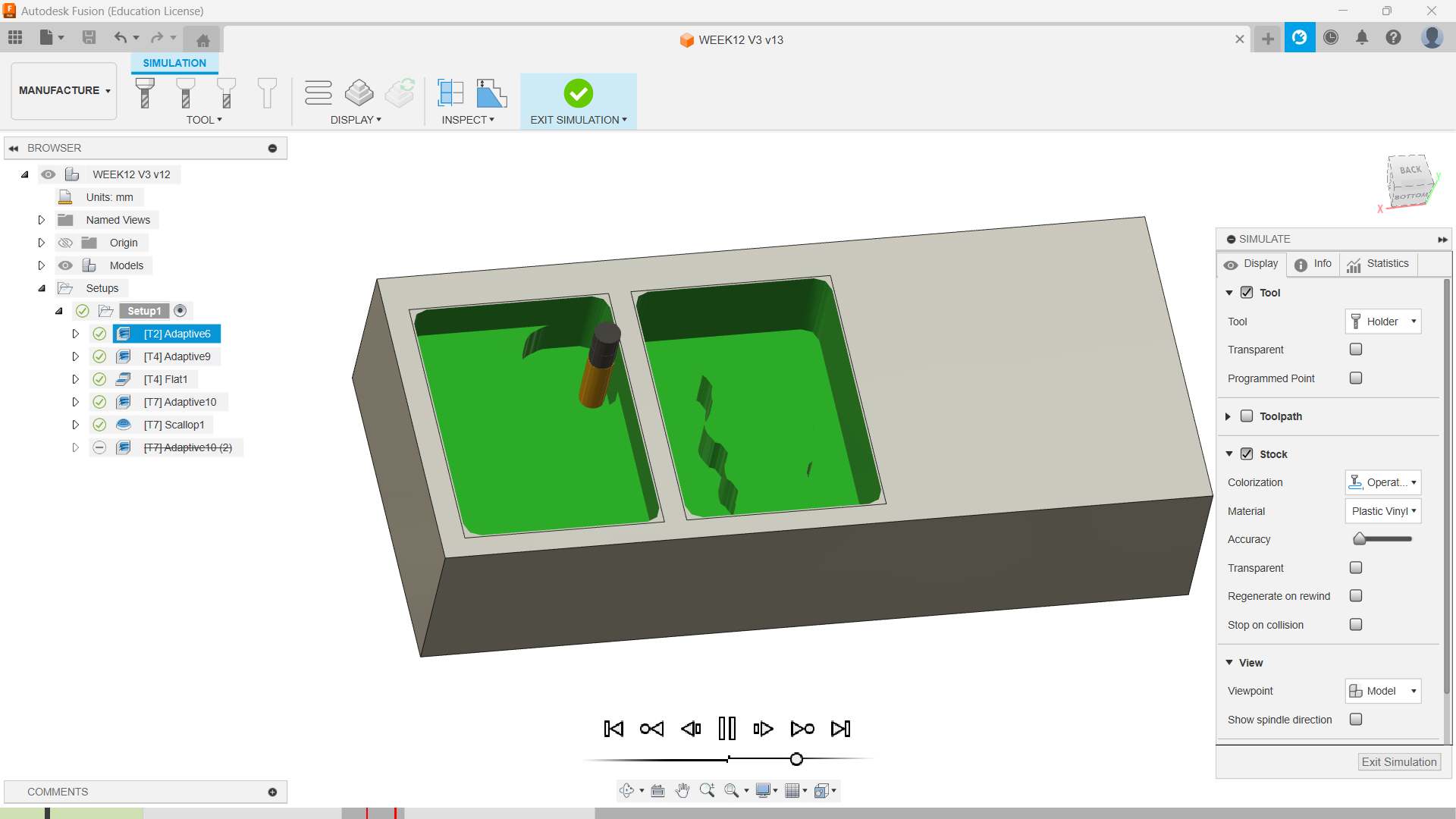
🚨
The image below illustrates the first adaptive operation using 6 mm end mill.
🚨
CAM simulation video is presented below.
>
Export G-code
🚨
The final step of the CAM is to export the G-code and upload it to the machine.
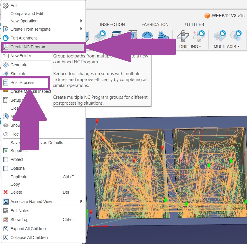
🚨
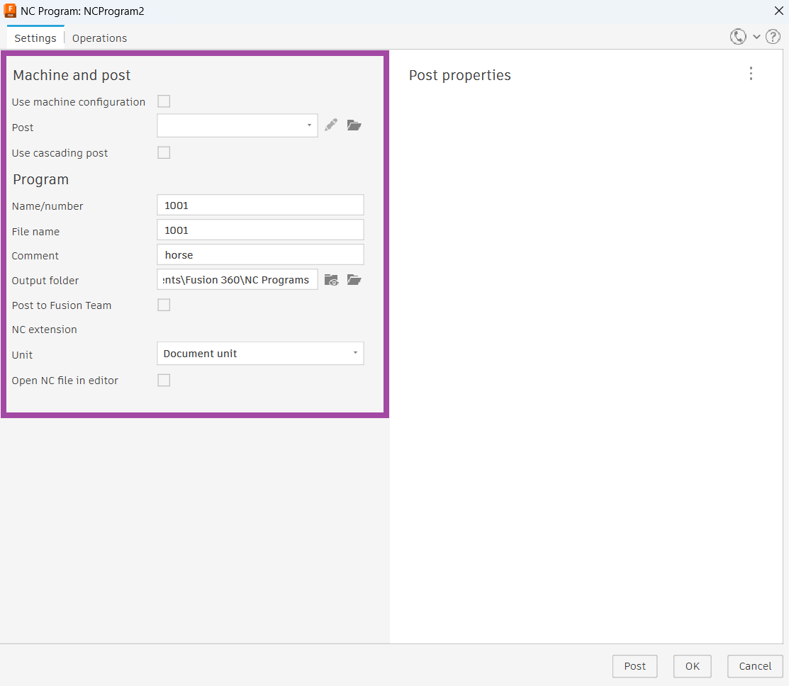
Right click the setup and either click on “Create NC Program” or “Post Process”.
🚨
A new NC Program dialogue box will appear, and you can fill in the required details, such as file name, folder path, and so on, from the ”setting” tab.
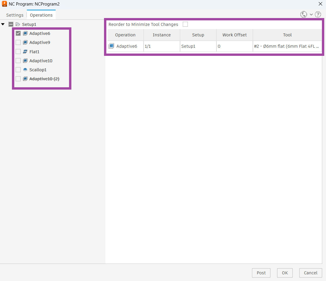
🚨
Select the “Operation” tab and select the G-code of the required operation.
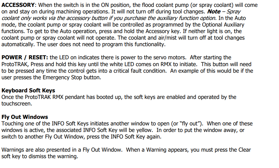
TRAK DPM RX2
The TRAK DPM RX2 is a bed mill that's designed for small lot and toolroom jobs. It has the same feel and footprint as a knee mill, but with more capacity and strength.
⬇️
Follow the link below to learn more about TRAK DPM RX2.
Before operating the TRAK, it is highly recommended to wear safety googles, and hand glove to protect our eye and prevent chips to sticking to our hand.
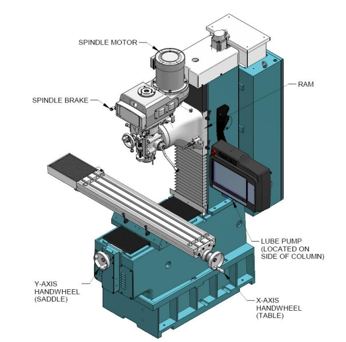
🚨
The photo below depicts the TRAK RX2 machine.
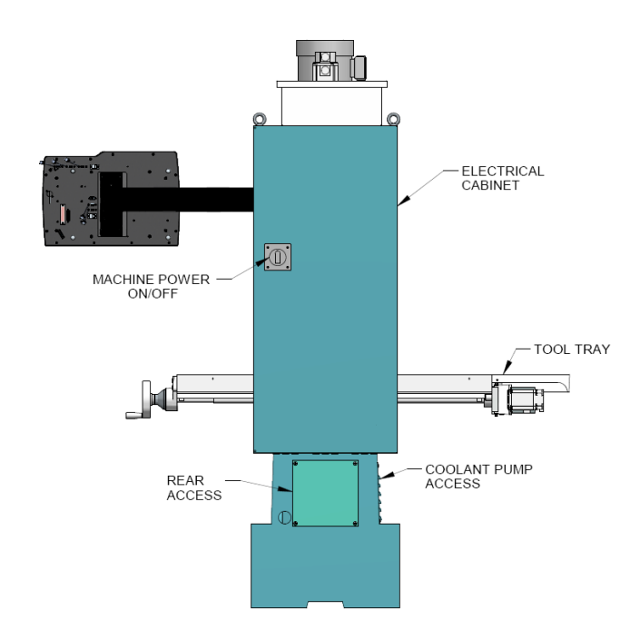
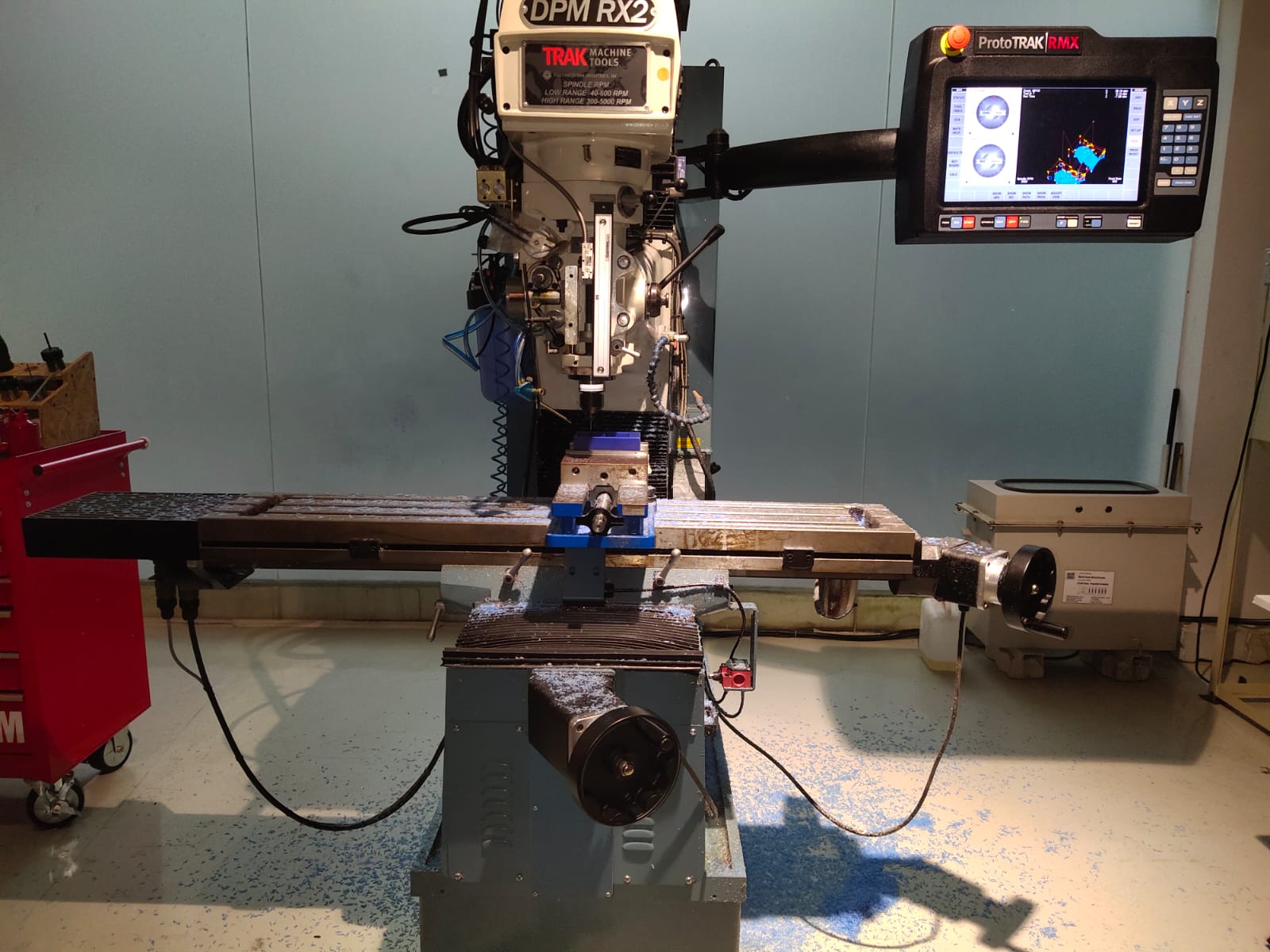
🚨
The photo below depicts the side view of the TRAK DPM RX2.
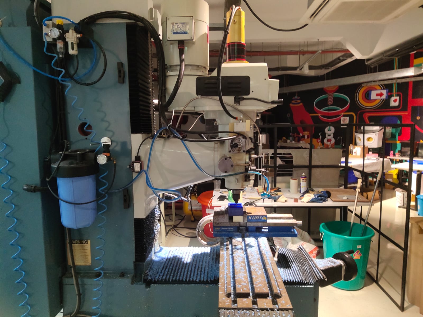
⚠️
A warning sign is placed on the back side of the TRAK.
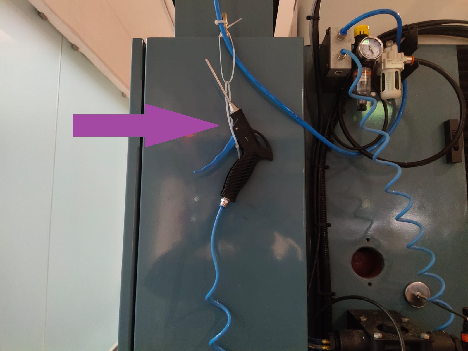
🚨
An air blower is provided at the side by a TRAK RX2.
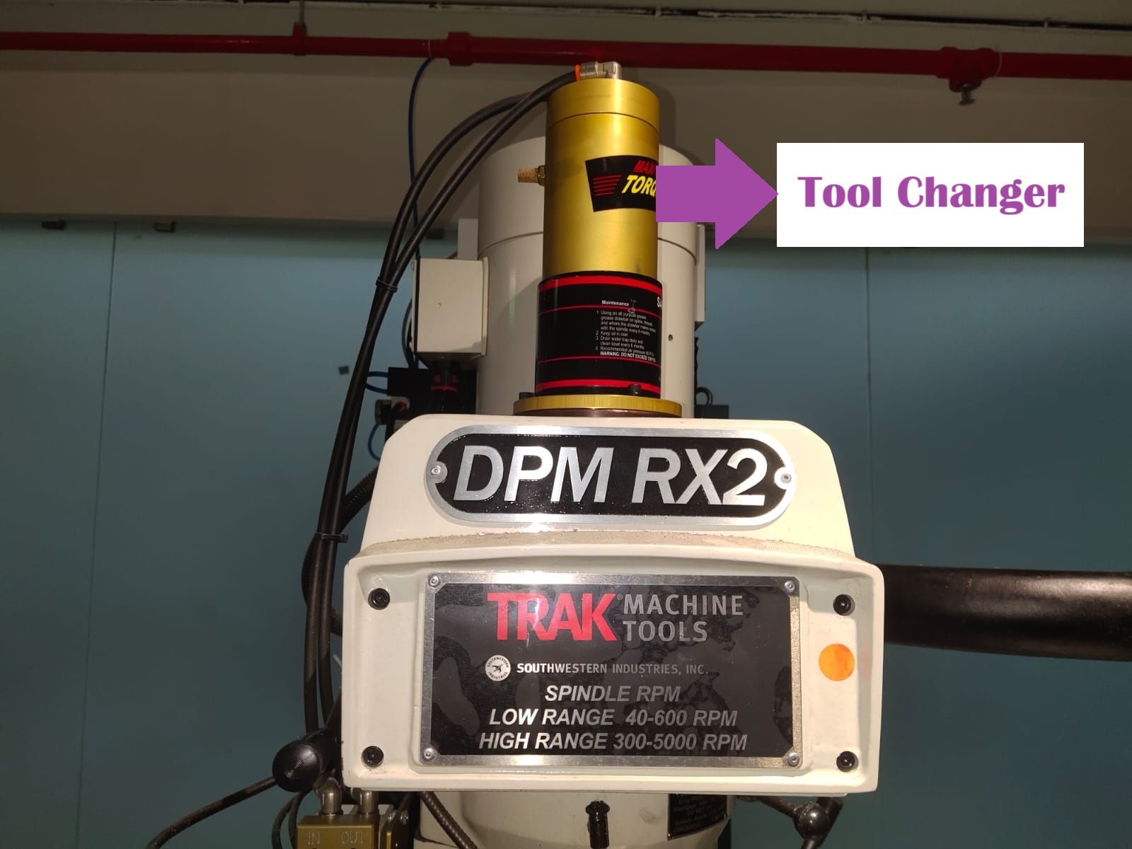
🚨
The tool changer of the TRAK RX2 is a pneumatic system and which is illustrated below.
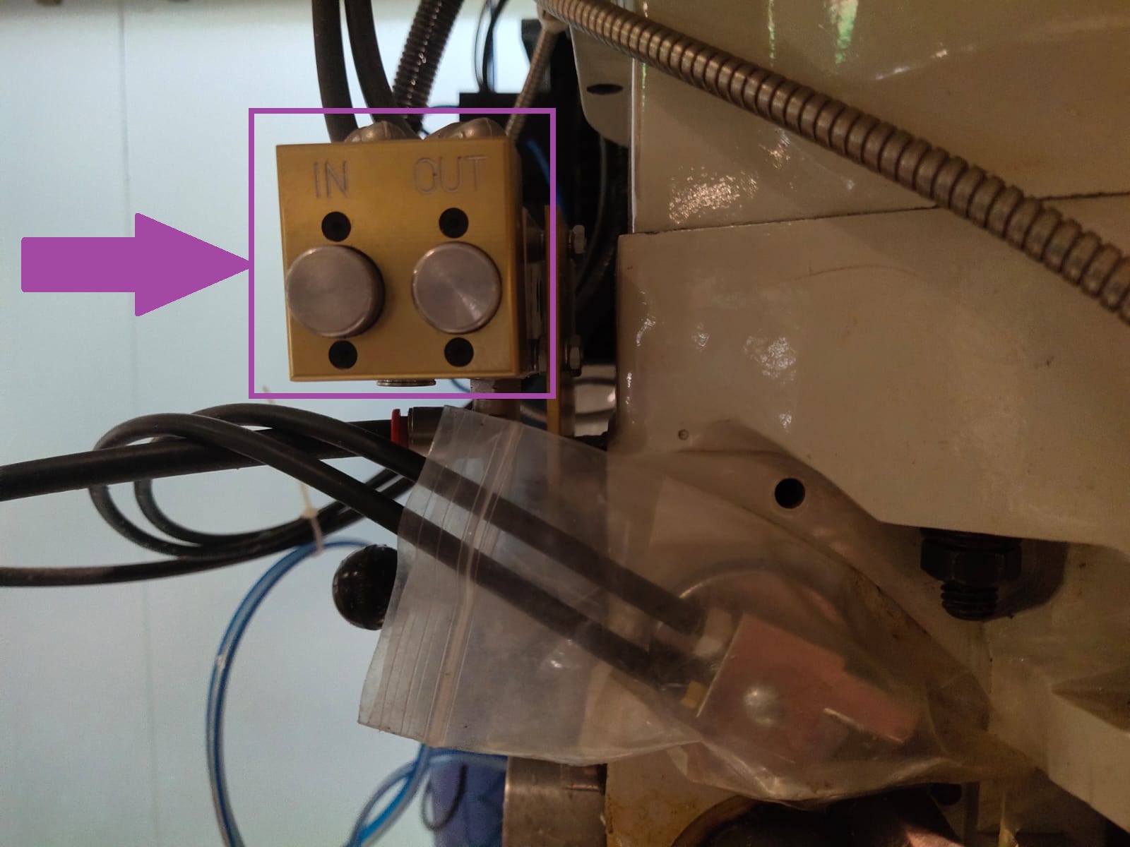
🚨
For changing the tools from the chuck there is a pneumatic system.
🚨
Pressing the in and out button ejects and holds the tool in place.
🚨
To insert the tool, place the tool inside the chuck and press the in button.
🚨
To eject the tool, hold the tool properly and press the out button.
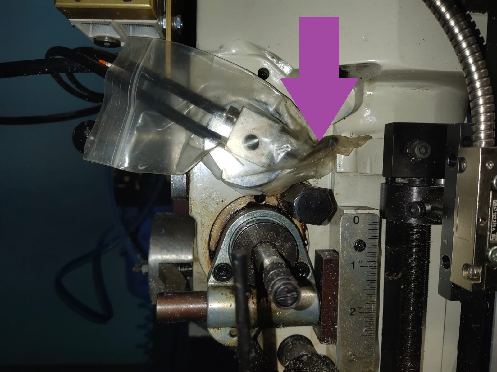
🚨
There is a coolant provided and the on-off switch is illustrated below.
🚨
The bench vise holds the machinable wax, as shown below.
🚨
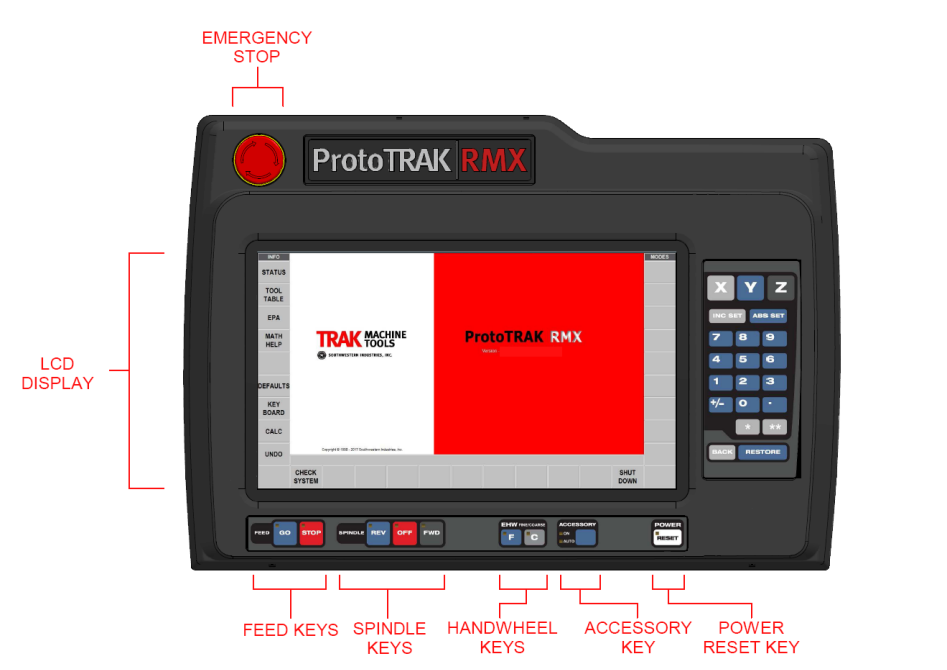
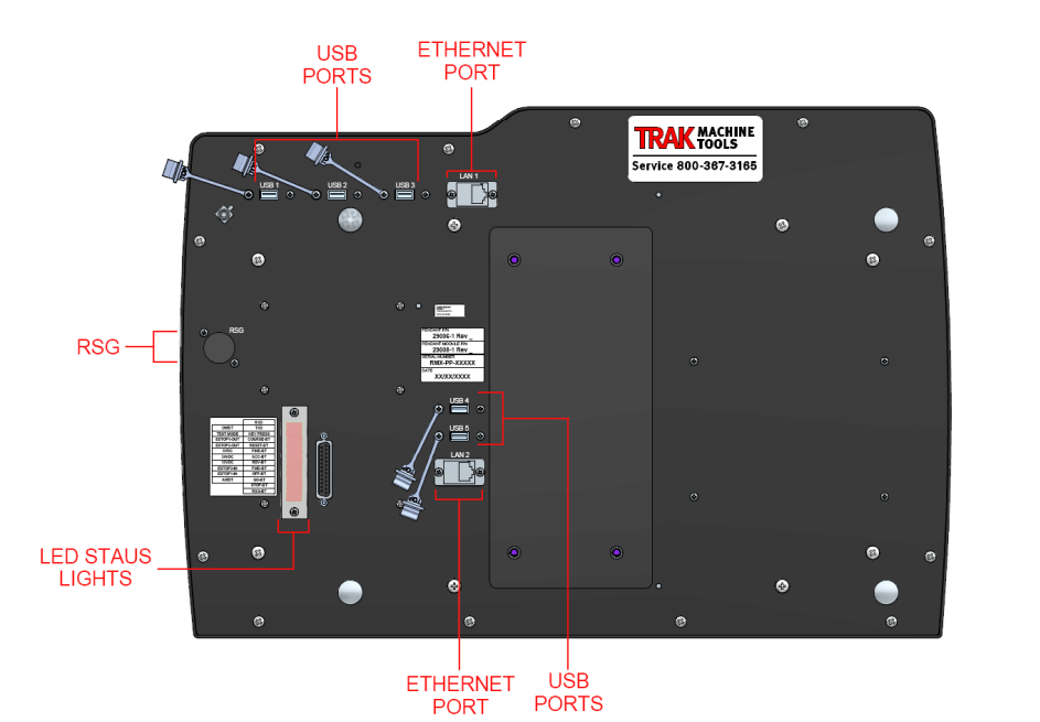
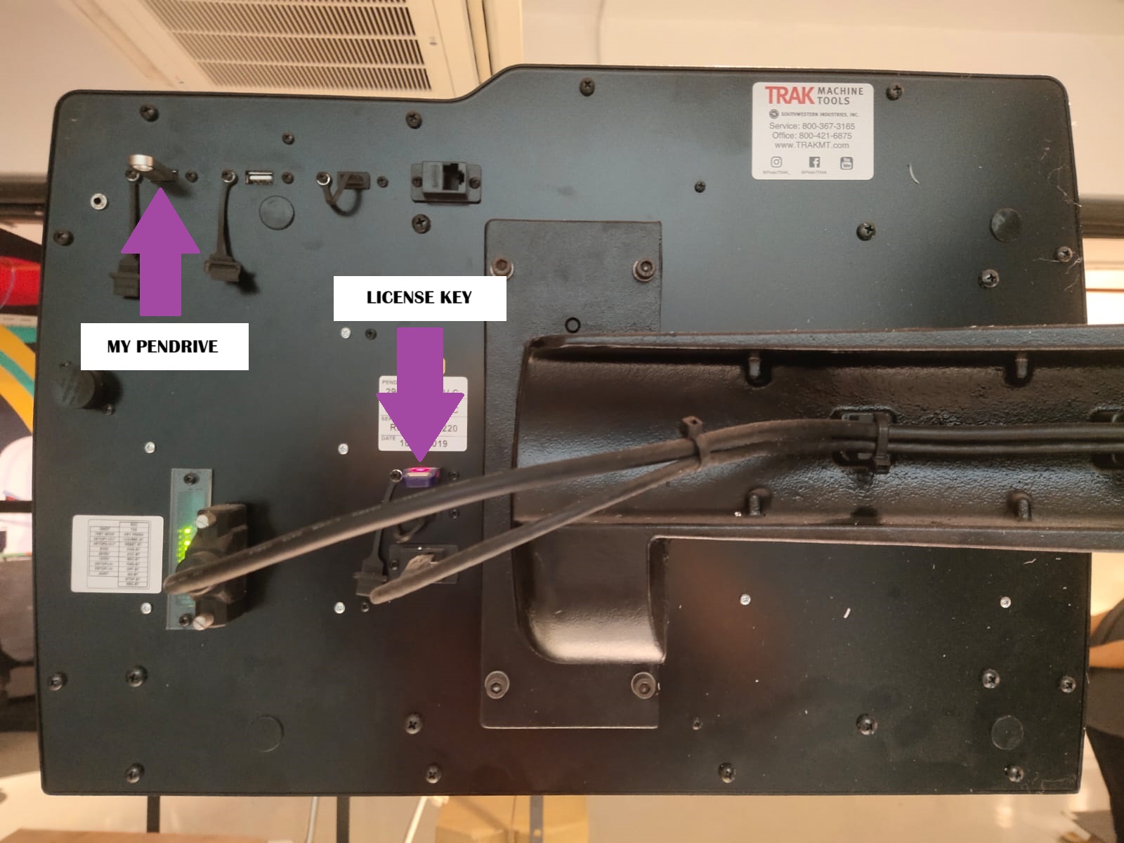
A touch screen is provided to control the TRAK. In order to upload the G-code we need to insert our pen drive to USB port provided below.
⚠️
Do not remove the license key from the machine. The license key is illustrated below.
🚨
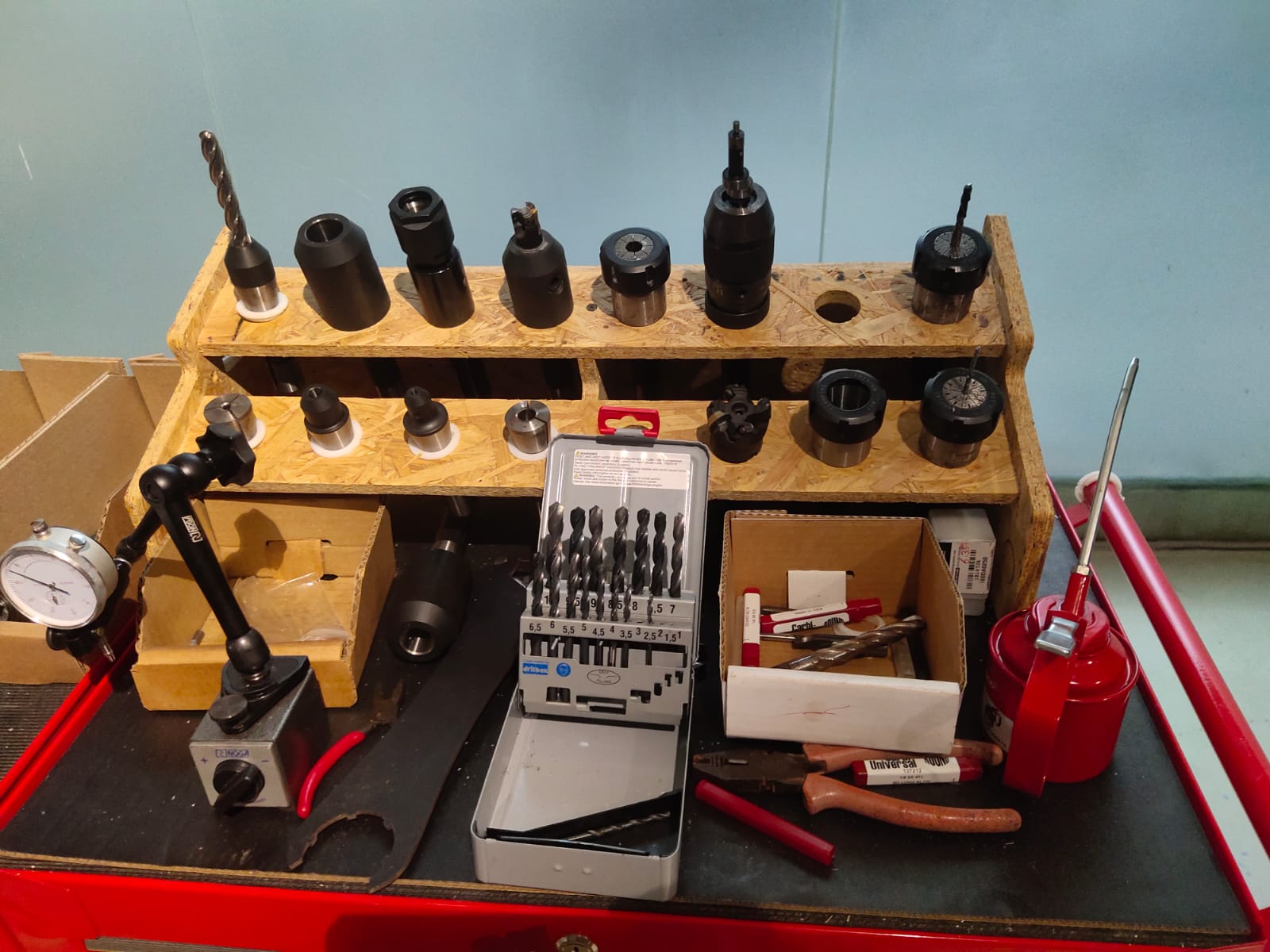
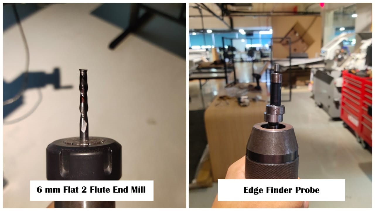
The photo below illustrates the various tools used for the TRAK.
🚨
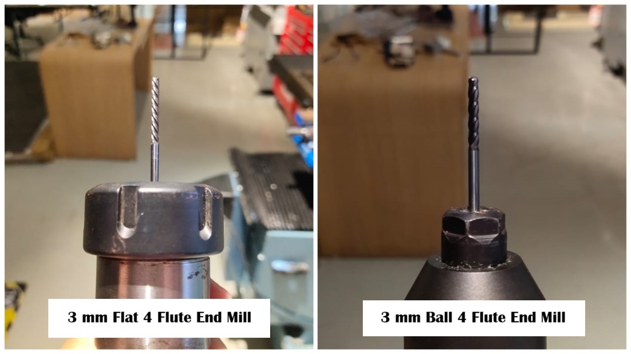
In my case, I used four different tools, and they are shown below.
Machining the Wax
🚨
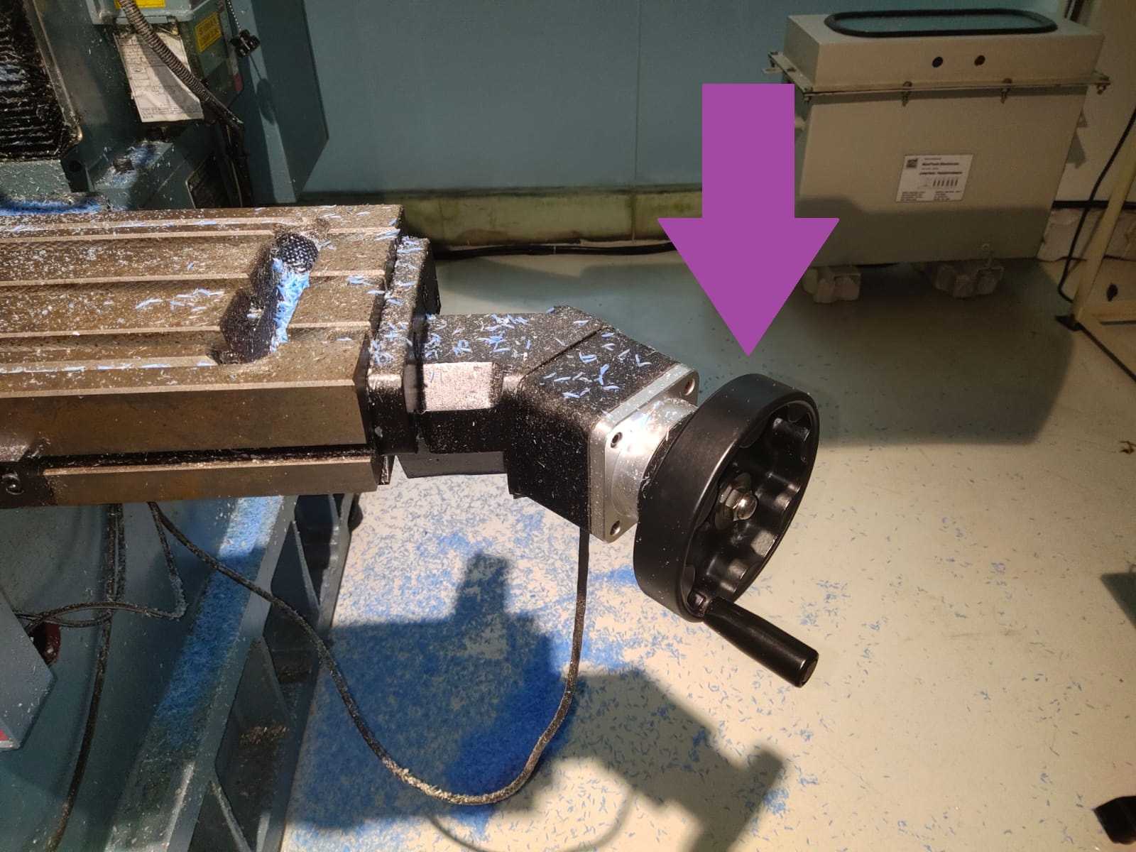
On the machine's right side, a hand wheel is provided for moving the X-axis. The hand wheel for the X-axis is shown below.
🚨
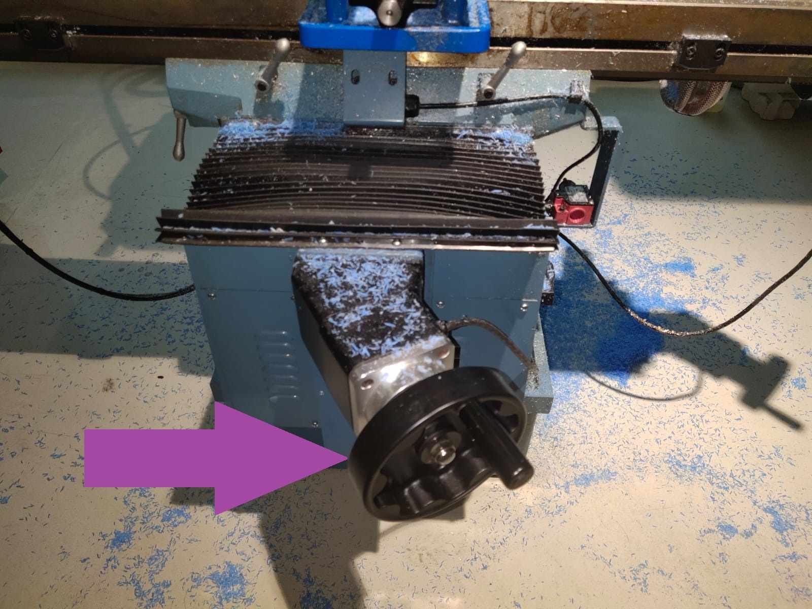
To move the Y-axis, there is a hand wheel provided on the front of the machine. The Y-axis hand wheel is illustrated below.
🚨
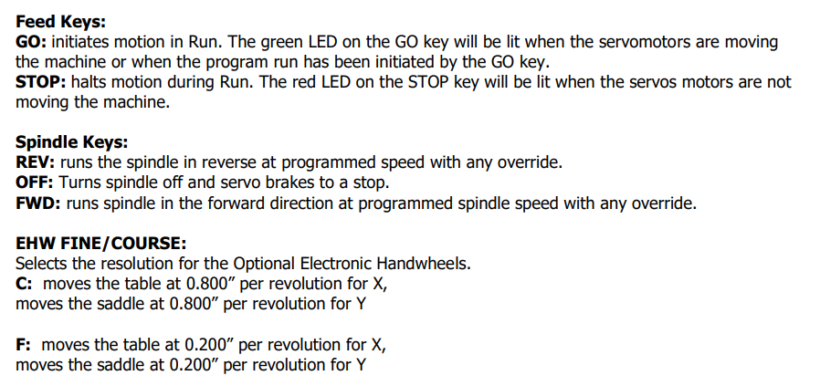
The same X-axis and Y-axis handwheel illustrated above can be used to run the G-code. Rotating the X-axis handwheel in clockwise direction will run the G-code forward, and rotating the handwheel counter clockwise will run the reverse the G-code. Similarly, rotating the Y-axis handwheel in clockwise direction will run the G-code forward in a fine speed, and rotating the handwheel counter clockwise will run the reverse the G-code in fine speed.
🚨
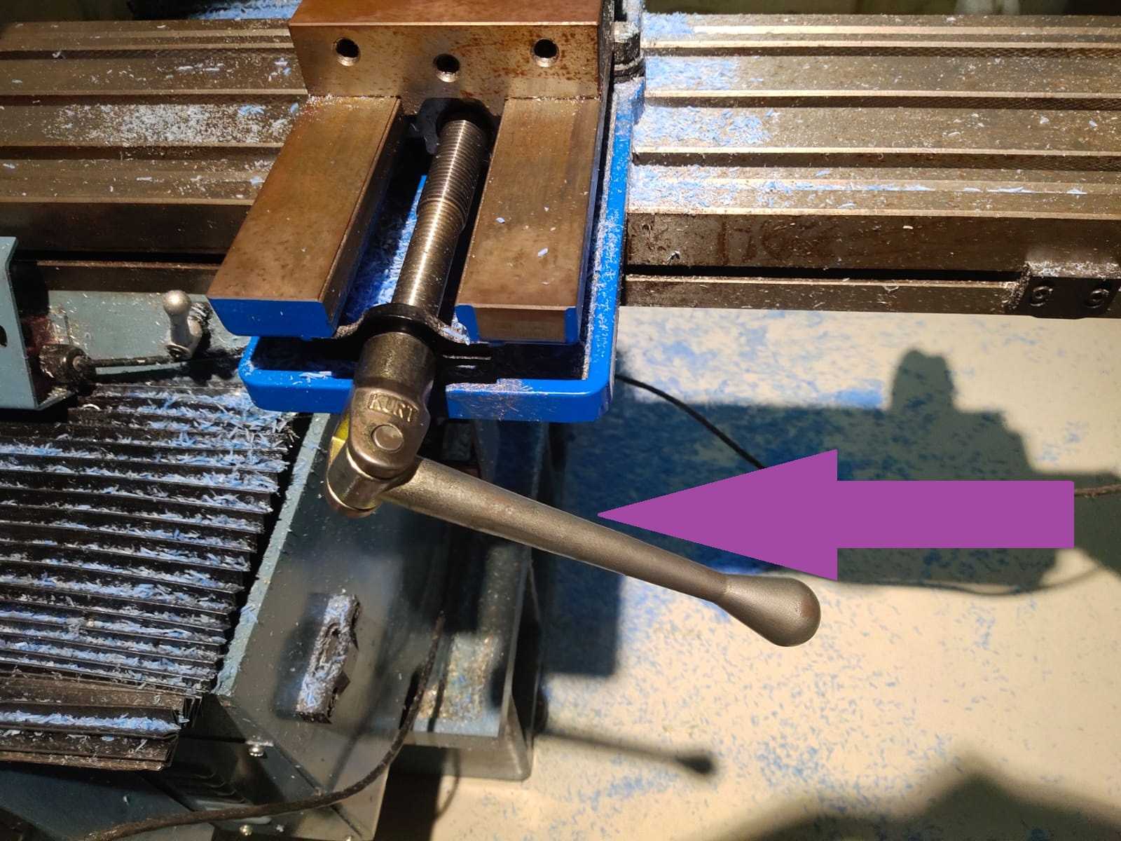
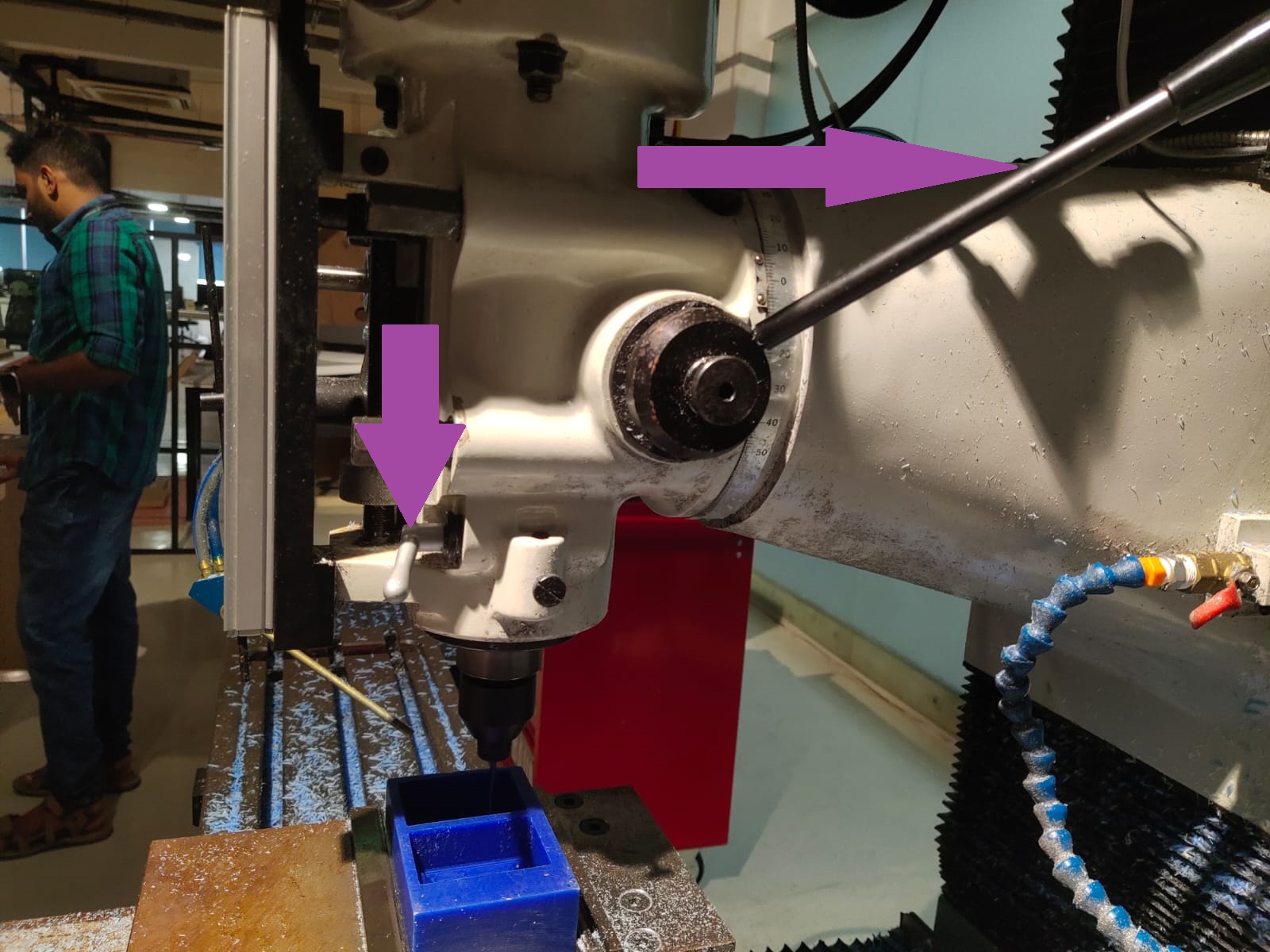
We can jog the X, Y, and Z-axis from the screen itself. However we can move the X, Y-axis using the handwheels and Z-axis using the lever mentioned below. A lock is provided to lock the lever properly.
Setting the Origin
🚨
The first step is to set the origin of the work piece. To set the origin I used Edge finder probe. I decided to set the origin at one corner.
🚨
Insert the edge finder probe.
🚨
Make sure to move to DRO tab and edge finder is on the lest hand side of the wax.
🚨
Turn on the spindle
🚨
Press the “F” (fine) button and move along the x axis using the handwheel. Check the edge finder probe, and as we move the tool towards the wax, the probe will start to align properly. Stop rotating the wheel once the probe is misaligned.
🚨
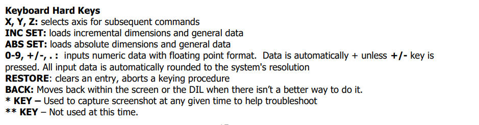
Then press “ABS SET” from the keypad.
⚠️
The diameter of the probe is 4 mm, so add 2mm to the x value.
🚨
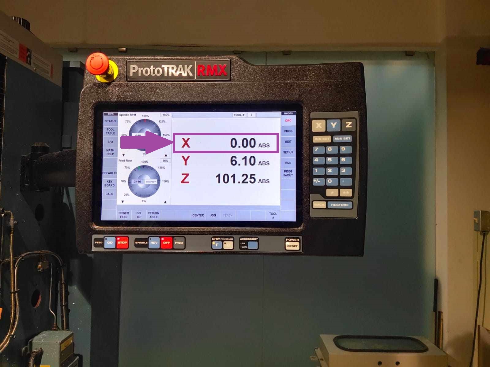
Press again “ABS SET” from the keypad to set the X to zero.
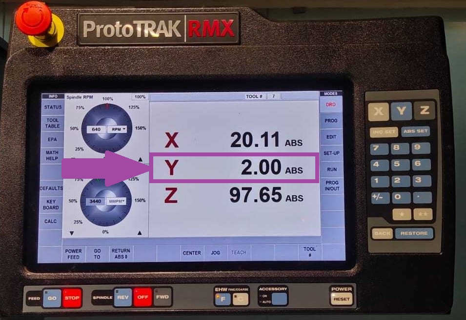
🚨
The image below illustrates the picture of the screen where the X is set to zero.
🚨
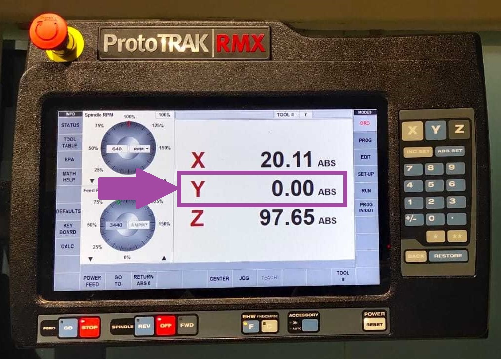
To set the Y-axis, follow the same procedure for X. Rotate the Y axis handwheel in fine mode and stop as soon as the probe is misaligned.
🚨
Then press “ABS SET”.
🚨
Add 2 mm to Y and again press “ABS SET”.
🚨
Now both the X and Y set.
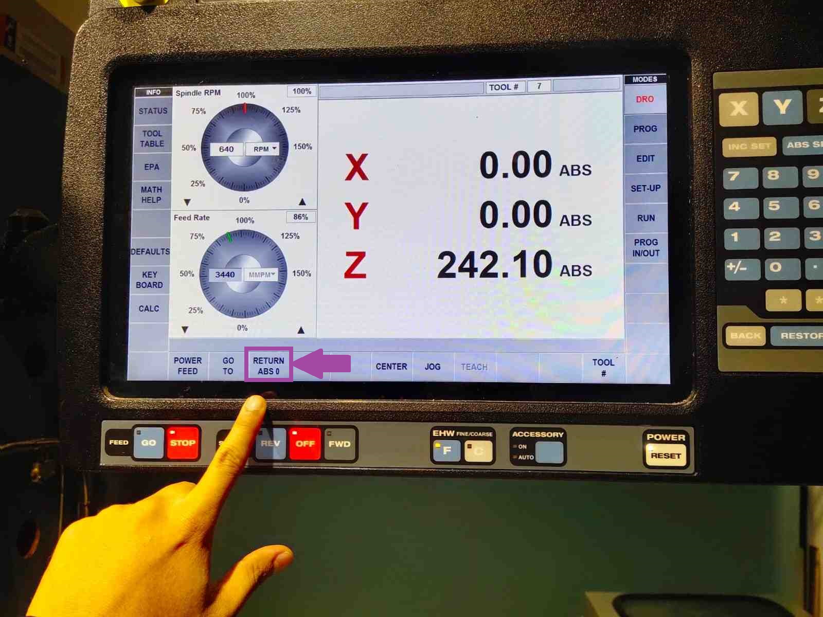
🚨
When we press the “RETURN ABS 0”.
🚨
then press “GO” buttonto move the tool to the origin.
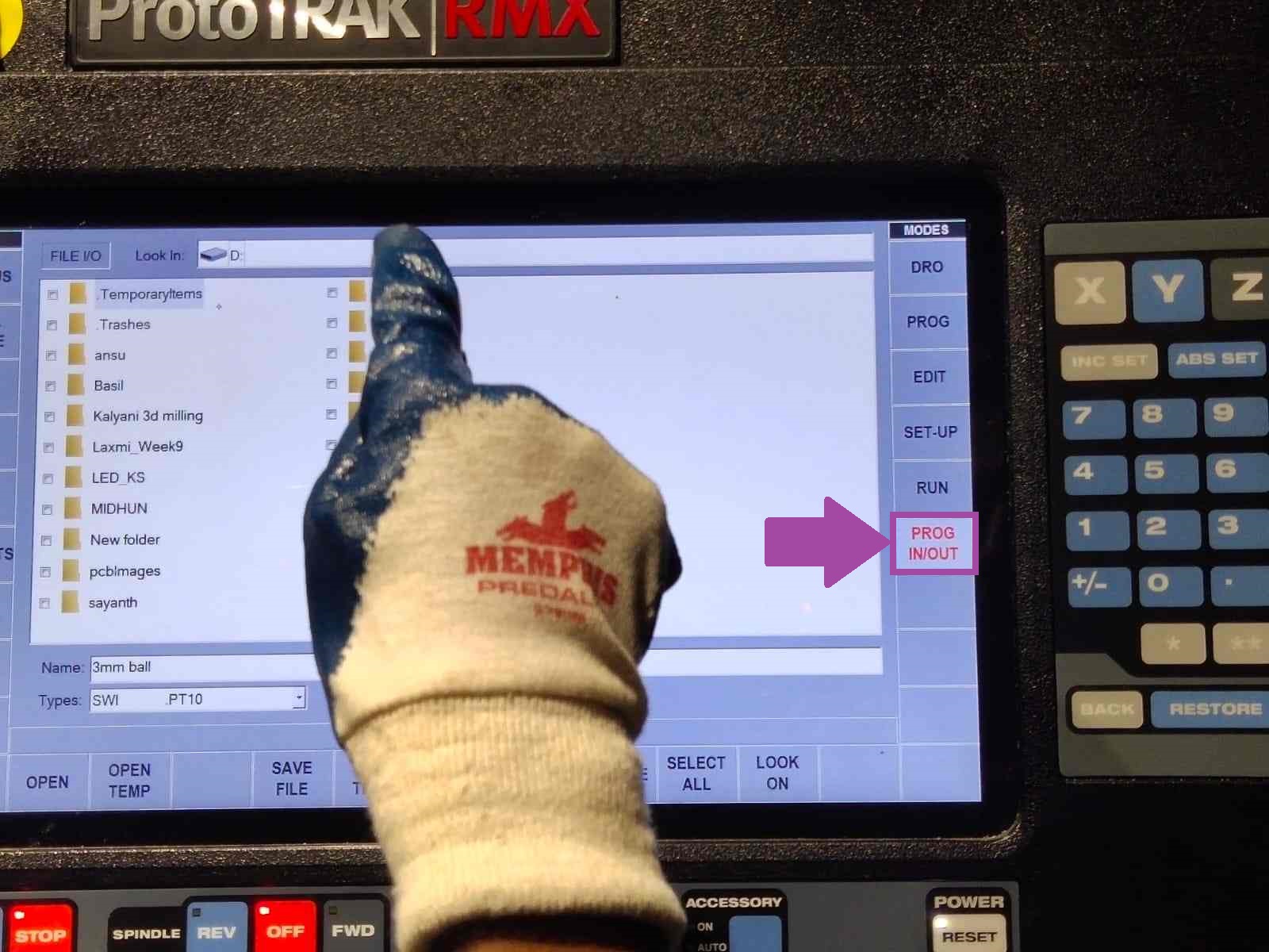
🚨
To load the G-code, insert the pen drive on the back of the screen, and select the “PROG IN/OUT” tab from the screen.
🚨
Select the file.
🚨
The image below illustrates the photo of the screen when the G-code is loaded.
🚨
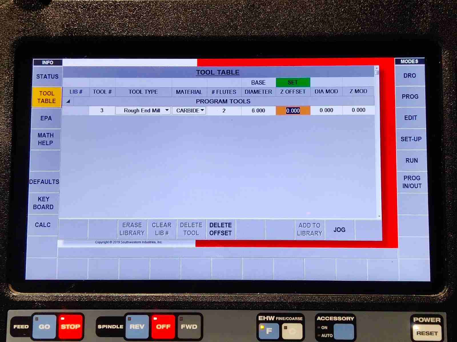
Now select the “TOOL TABLE” and add the details of the tool that you are using. For me, initially, I am using a 6mm rough end mill.
🚨
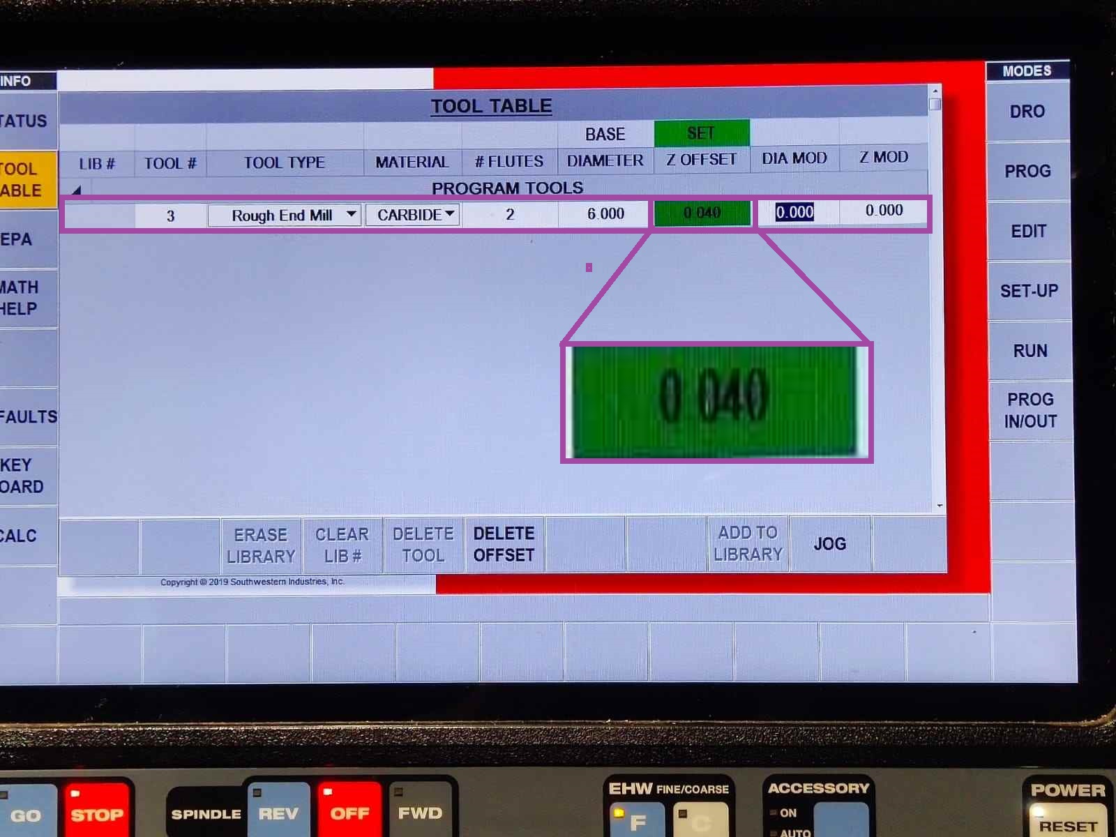
A important data to fill is the Z offset from the base and from the work piece.
🚨
We need to set the Z offset from the base only once, but each time when we change the tool we need to set the Z offset to zero.
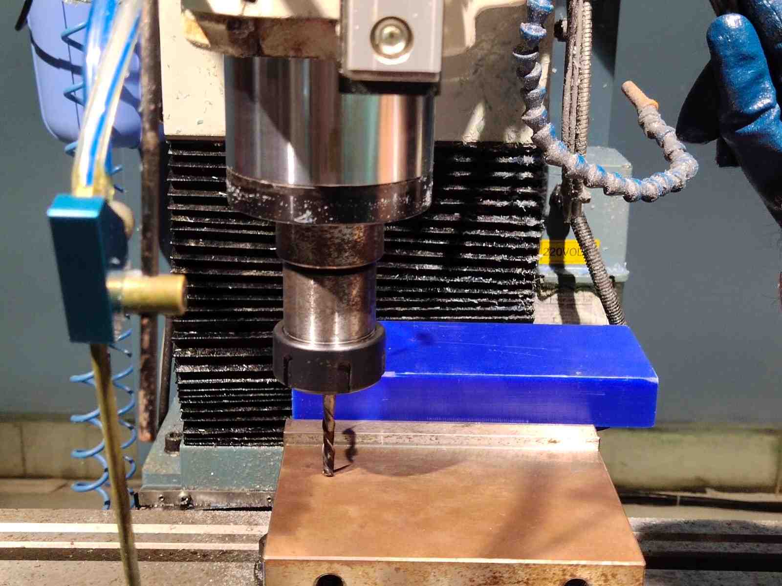
🚨
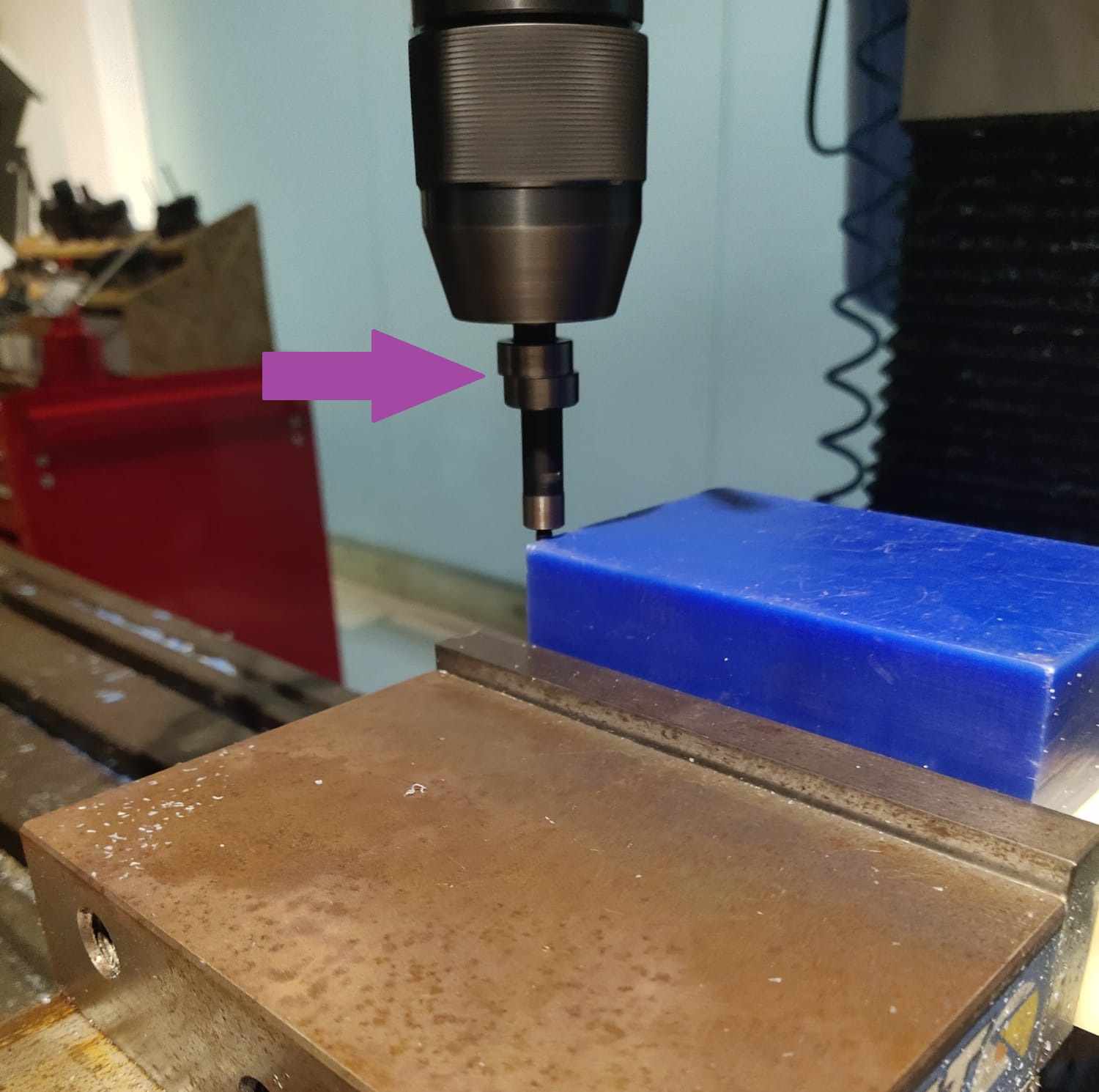
When the tool is changed place the tip of the tool as shown below using the lever and from the Z offset tab select ABS SET.
🚨
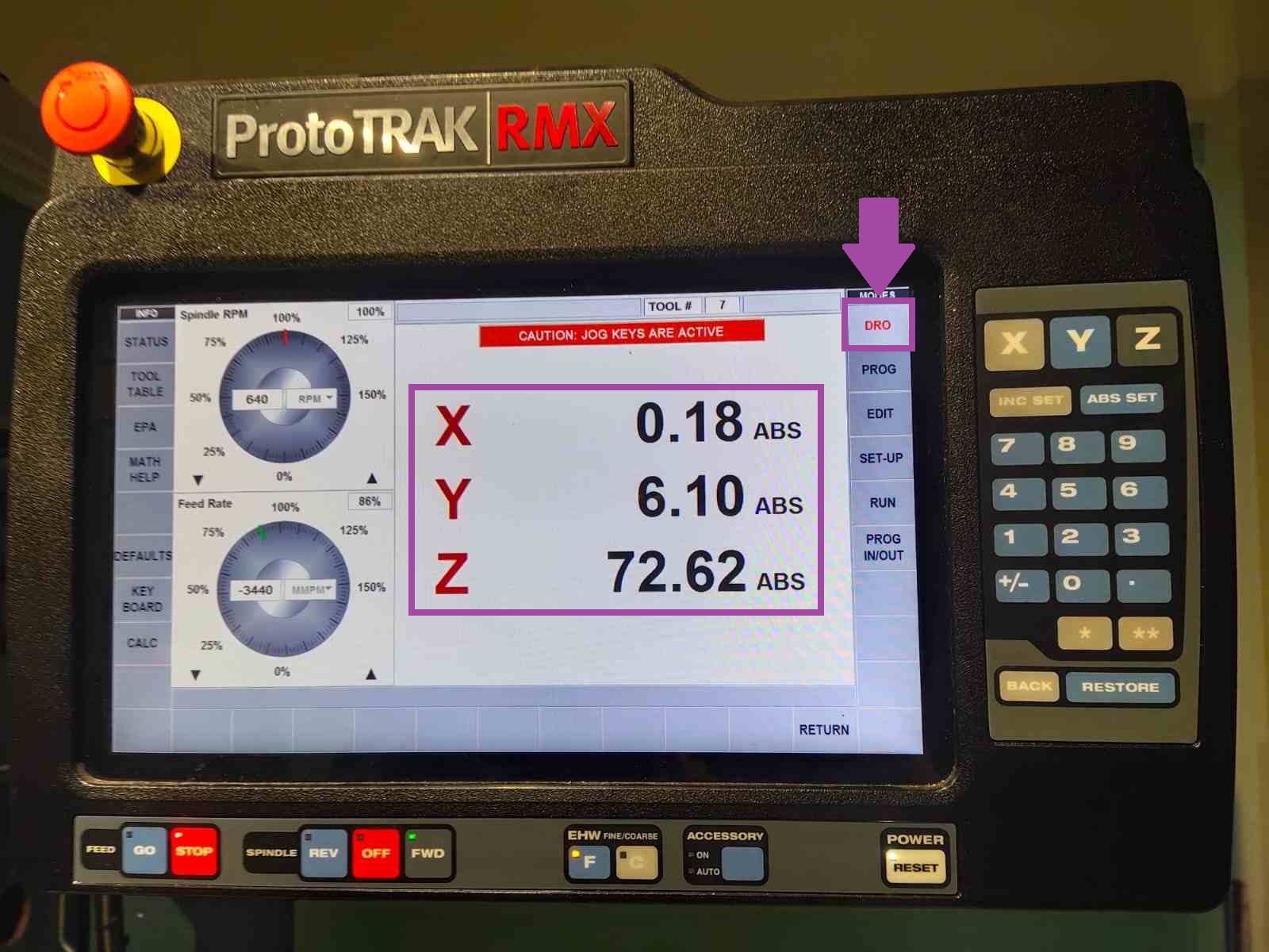
Now go to DRO tab.
🚨
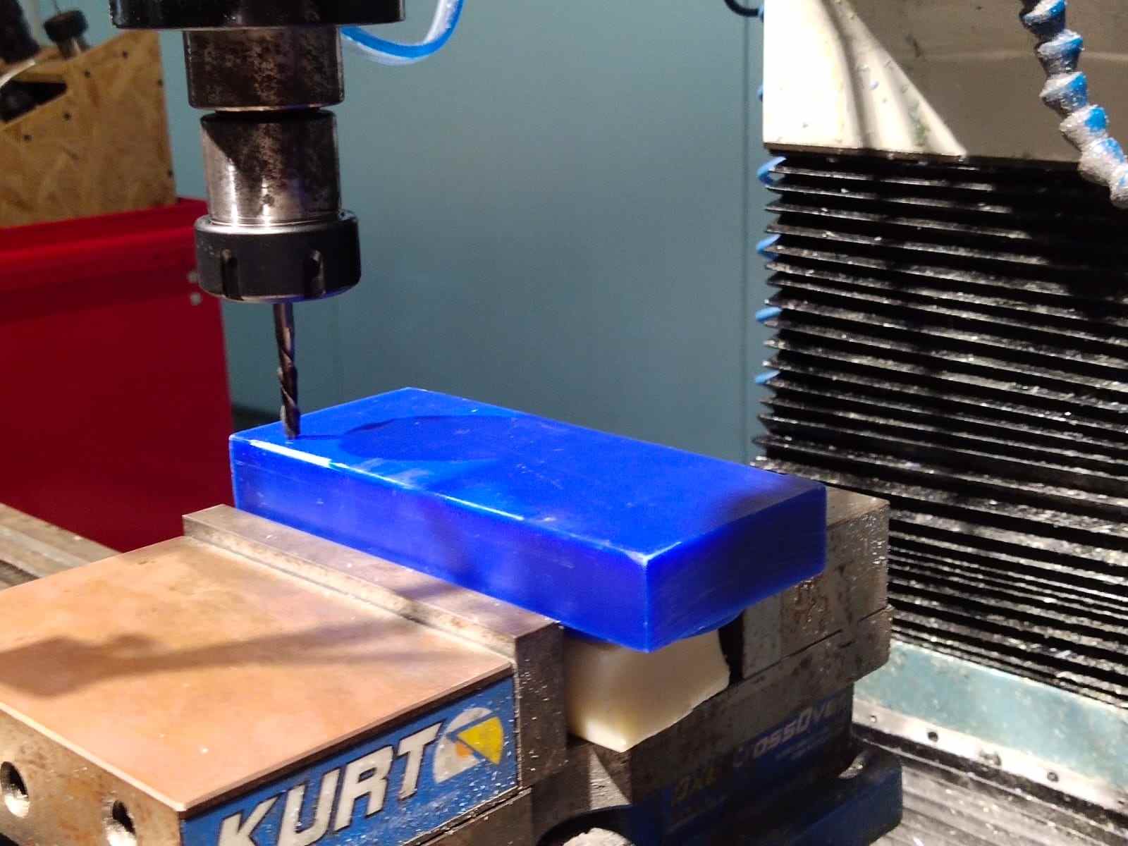
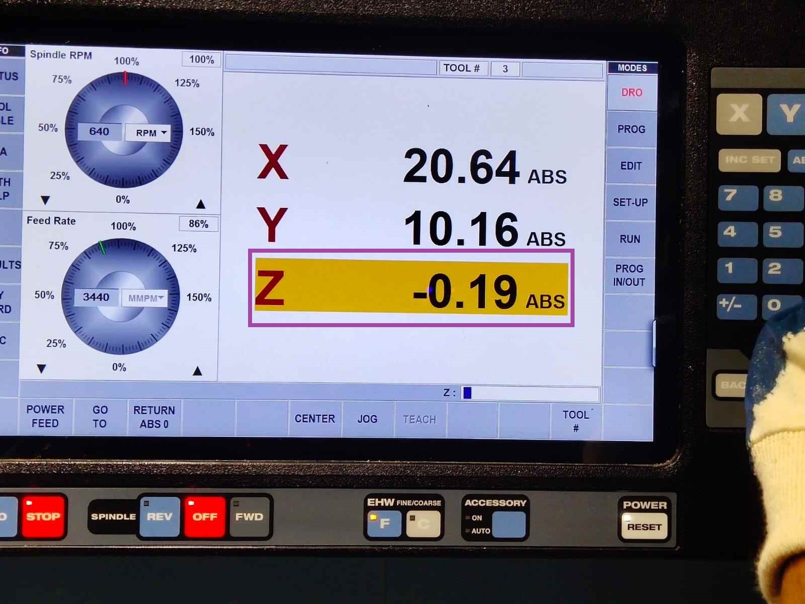
Now place the tip of the tool on top of the wax.
🚨
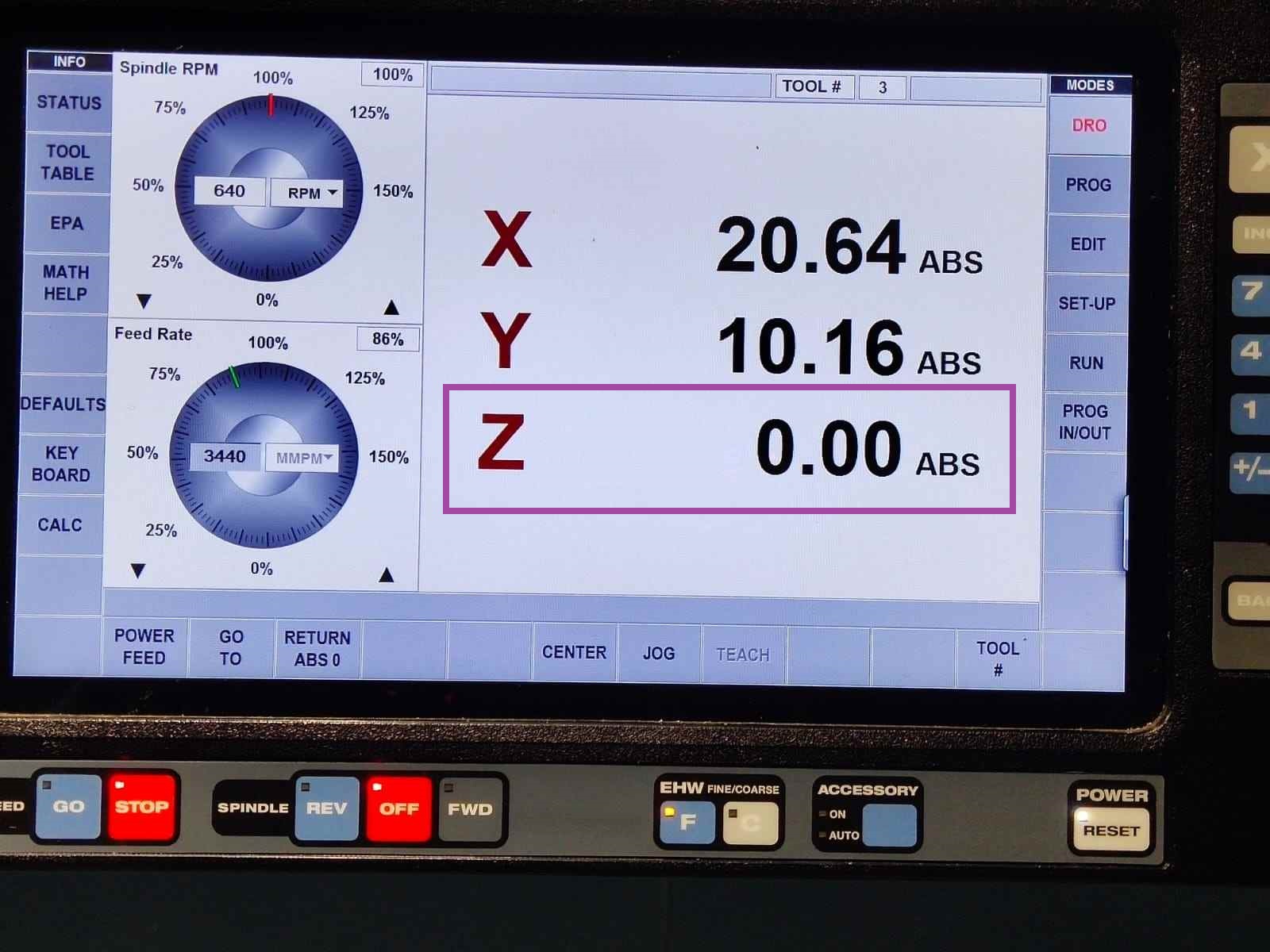
Select the Z axis.
🚨
then press “ABS SET”.
🚨
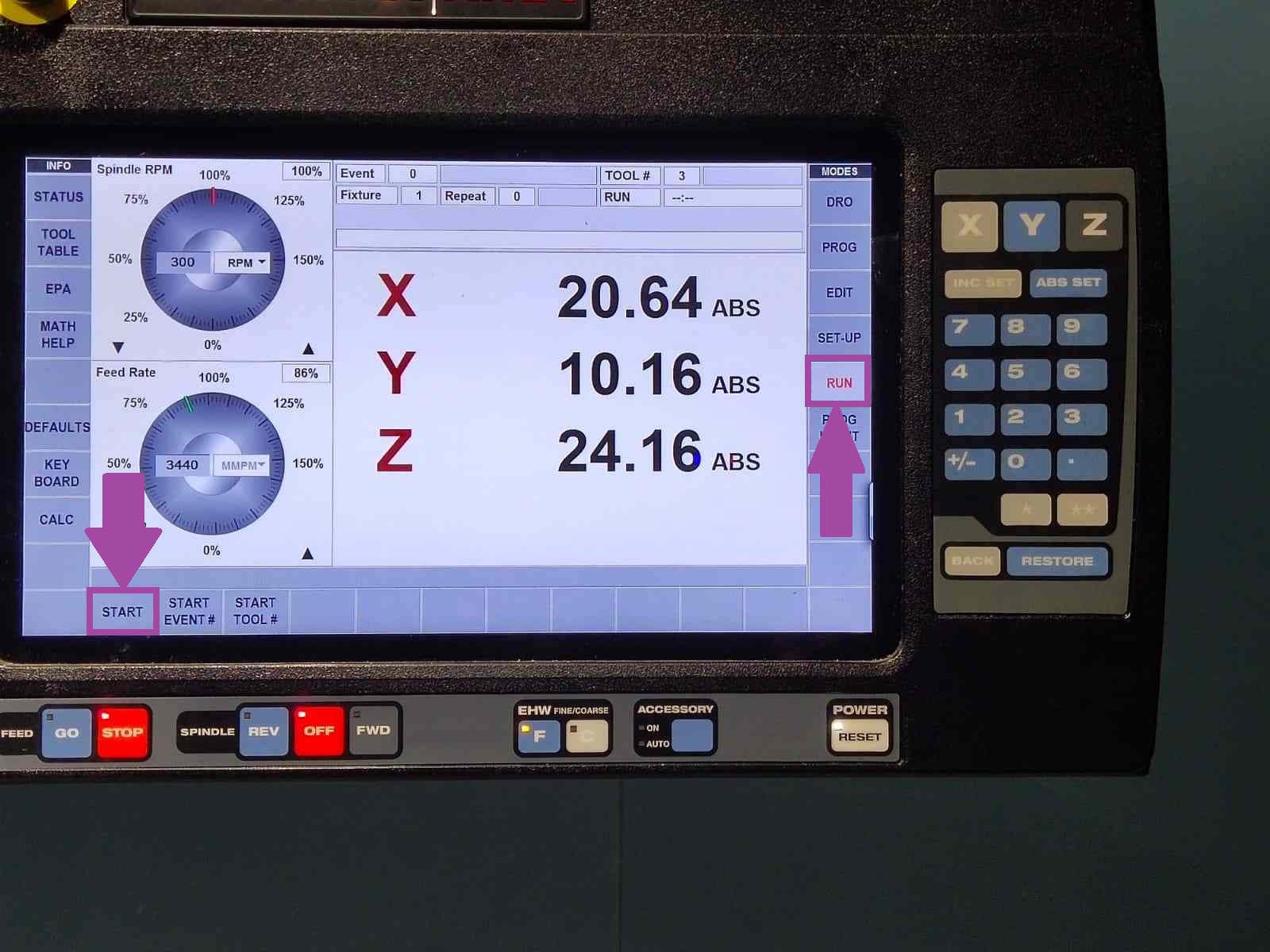
Click on “RUN” and press “START”.
🚨
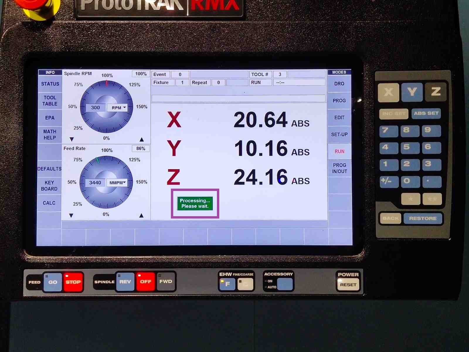
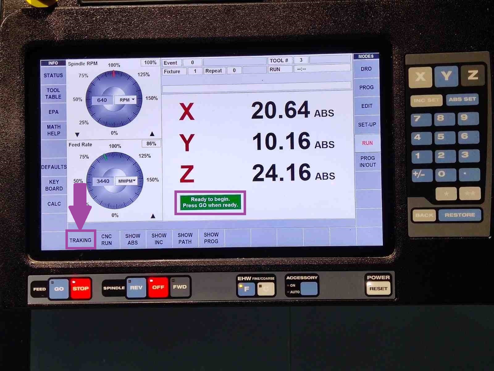
A message will be displayed on the screen, as shown below.
🚨
when the machine is ready to run another message will be displayed on the screen, as shown below.
🚨
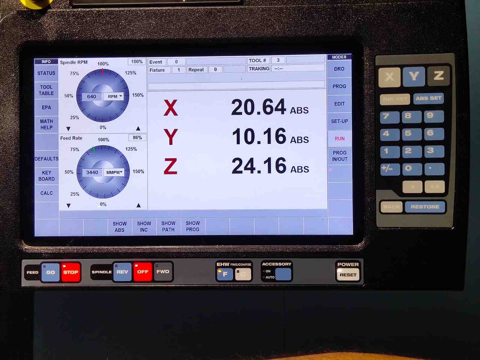
Now press “TRAKING” to check that everything is fine. This feature is amazing 🙂.
🚨
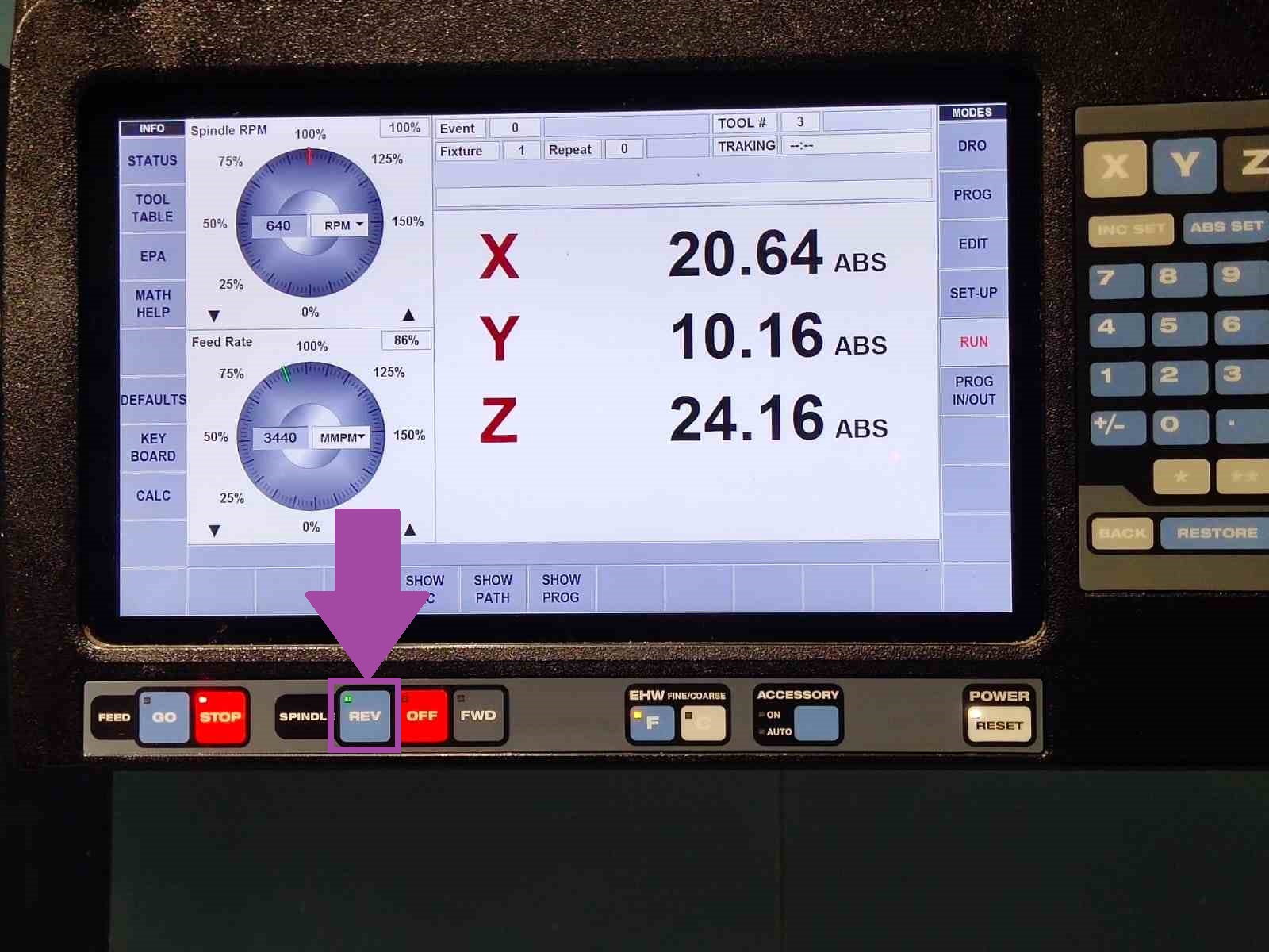
Now the spindle is off. To turn on the spindle in clockwise press FWD, and to turn on the spindle in anti-clockwise press REV.
🚨
In my case the tool is counter clock wise, so I selected REV.
🚨
Using the handwheels, we can run the G-code forward and backward. The X- axis handwheel is used to execute the G-code in coarse and Y-axis handwheel is used to execute the G-code in fine.
🚨
To reverse the G-code rotate the handwheel anti-clockwise
🚨
Once everything is fine, move two steps backward by rotating the handwheel anti-clockwise. Then exit from tracking mode and select “CNC RUN”.
🚨
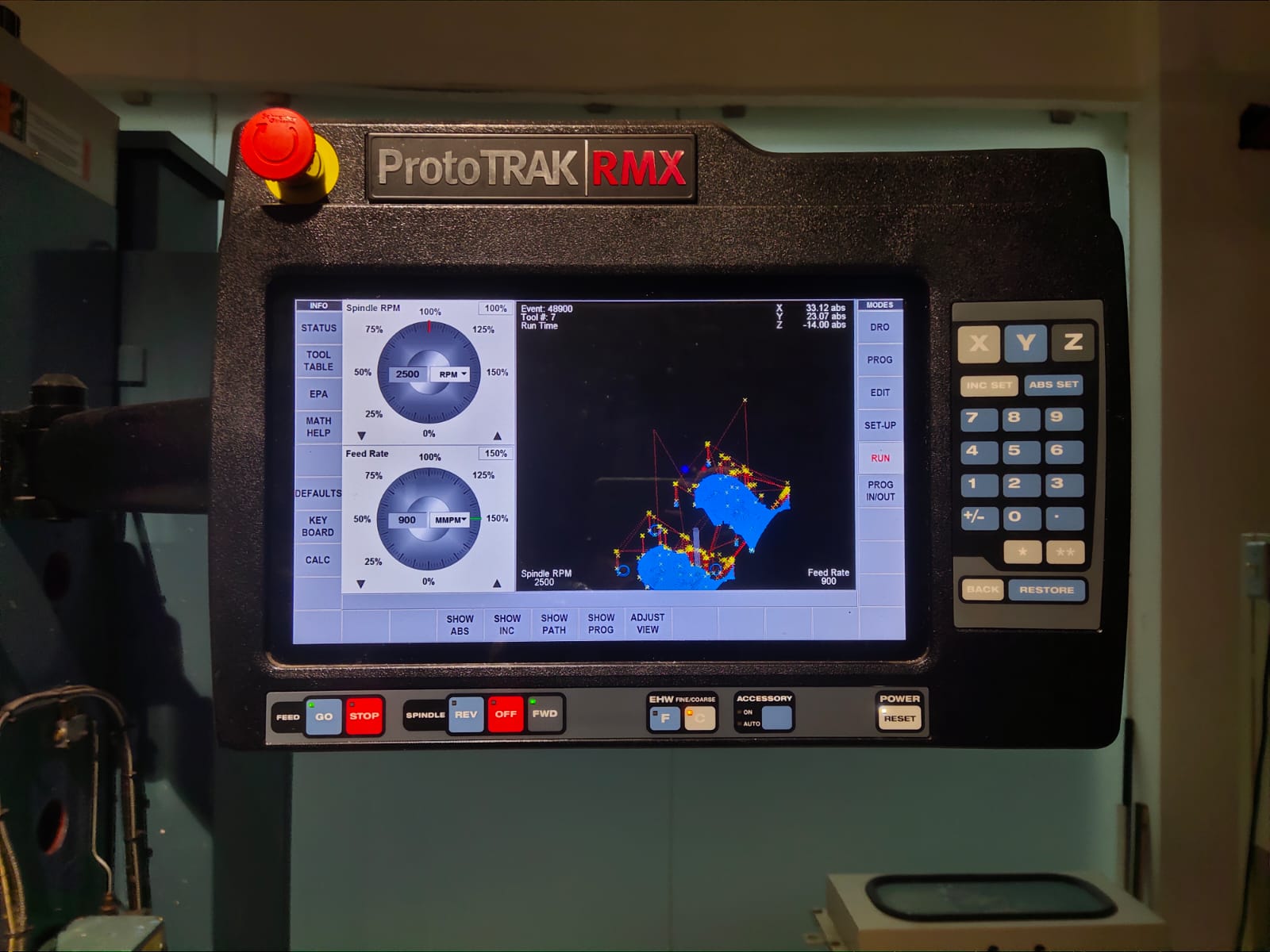
To view the tool path select on “SHOW PATH” from the screen.
🚨
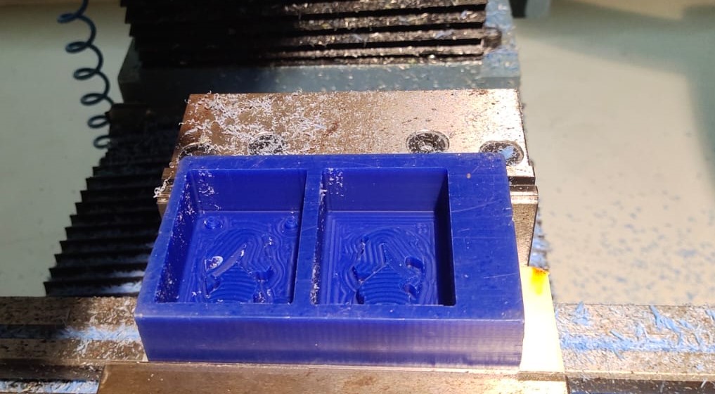
The photo below illustrates the wax after performing the adaptive operation with a 3mm flat end mill.
🚨
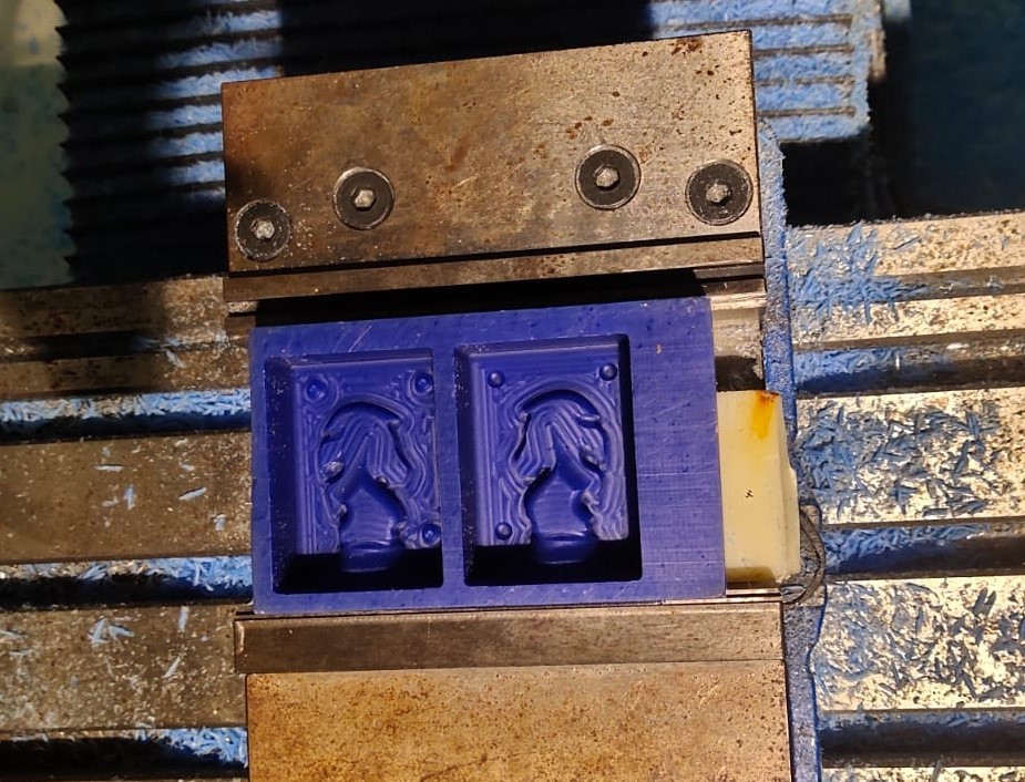
The photo below illustrates the wax after performing the adaptive operation with a 3mm ball end mill.
🚨
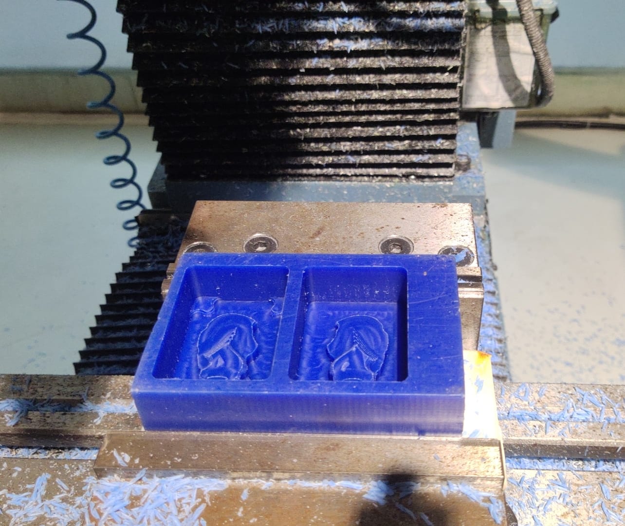
The photo below depicts the wax after performing the scallop operation with a 3mm ball end mill.
🚨
The milling video is provided below.
🚨
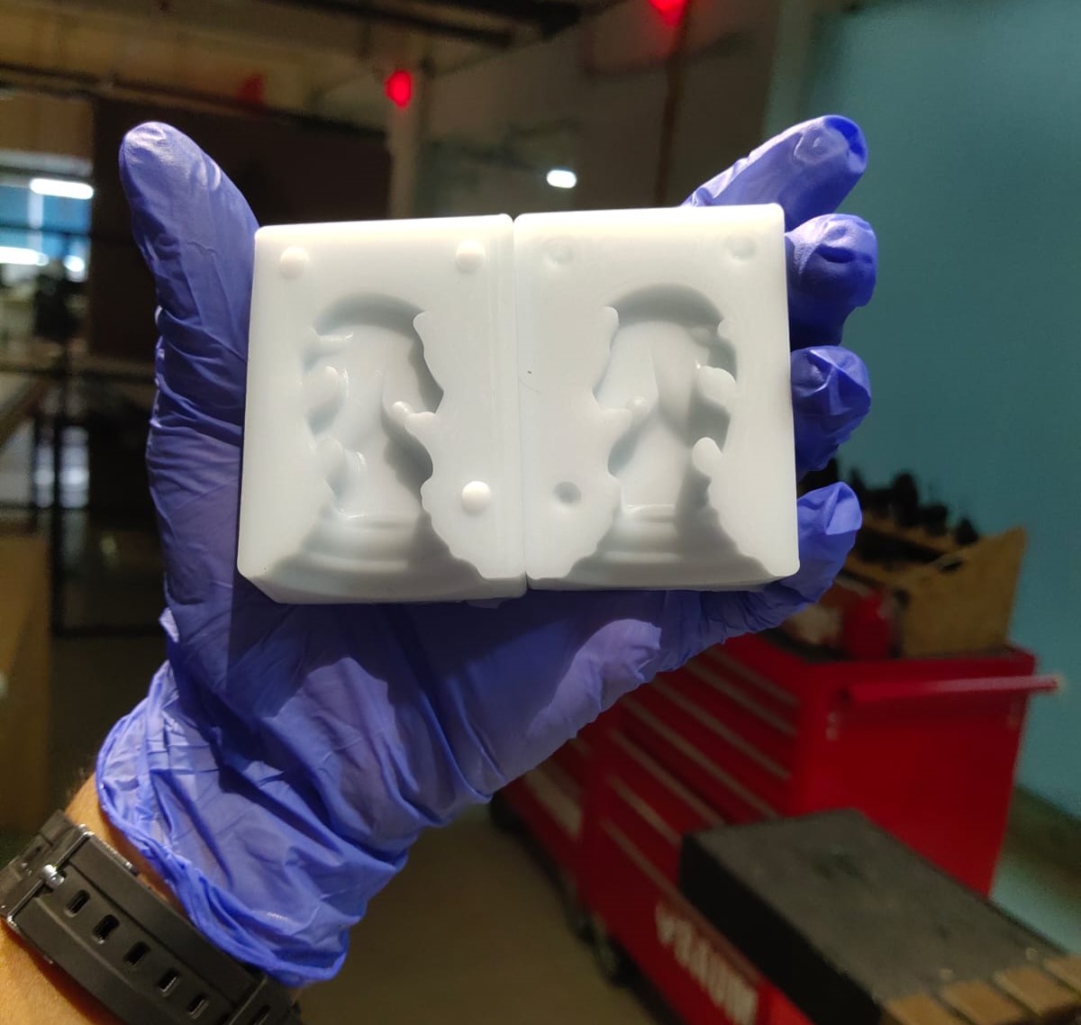
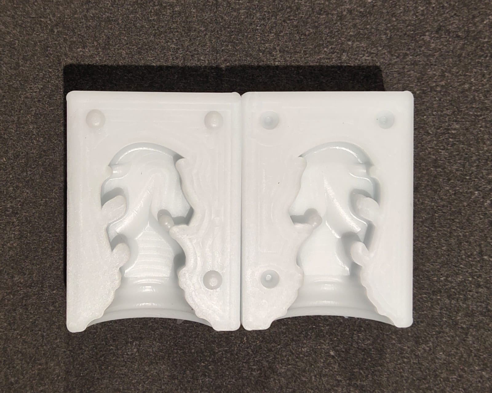
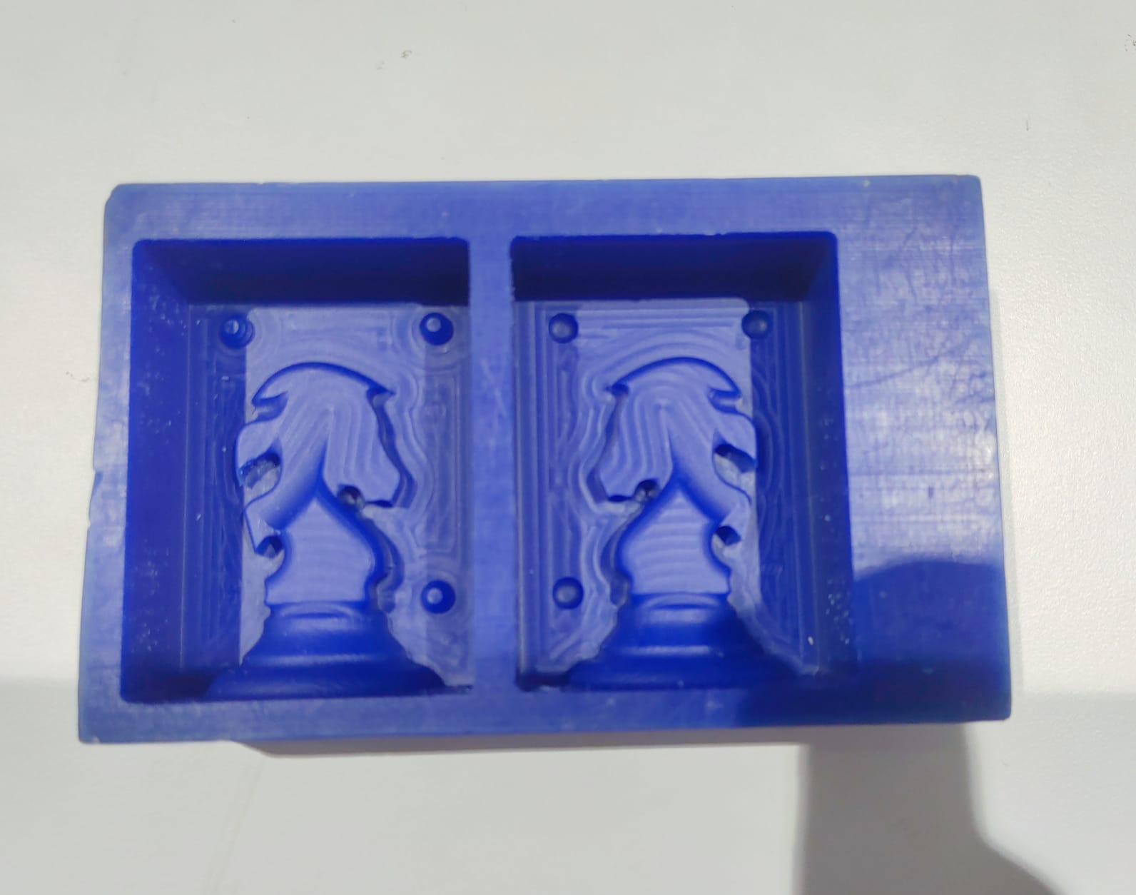
Final result of silicone mold milling.
Silicone Mold Casting
🚨
I made the decision to utilise water to clean the silicone mold before casting it, and I took this chance to discover more about our Fab lab's pressure washer, shown below.
🚨
The second step is to take the volume of our mold. I filled my mold with water and poured it into a transparent glass.
🚨
Then I marked the water level using a permanent marker.
🚨
Now it's time to use the silicone and the curing agent.
🚨
In our lab we have the “Aditya Silicone Rubber” and “Aditya Curing Agent”.
💠
The ratio of the silicone and the curing agent is 100 : 3.
🚨
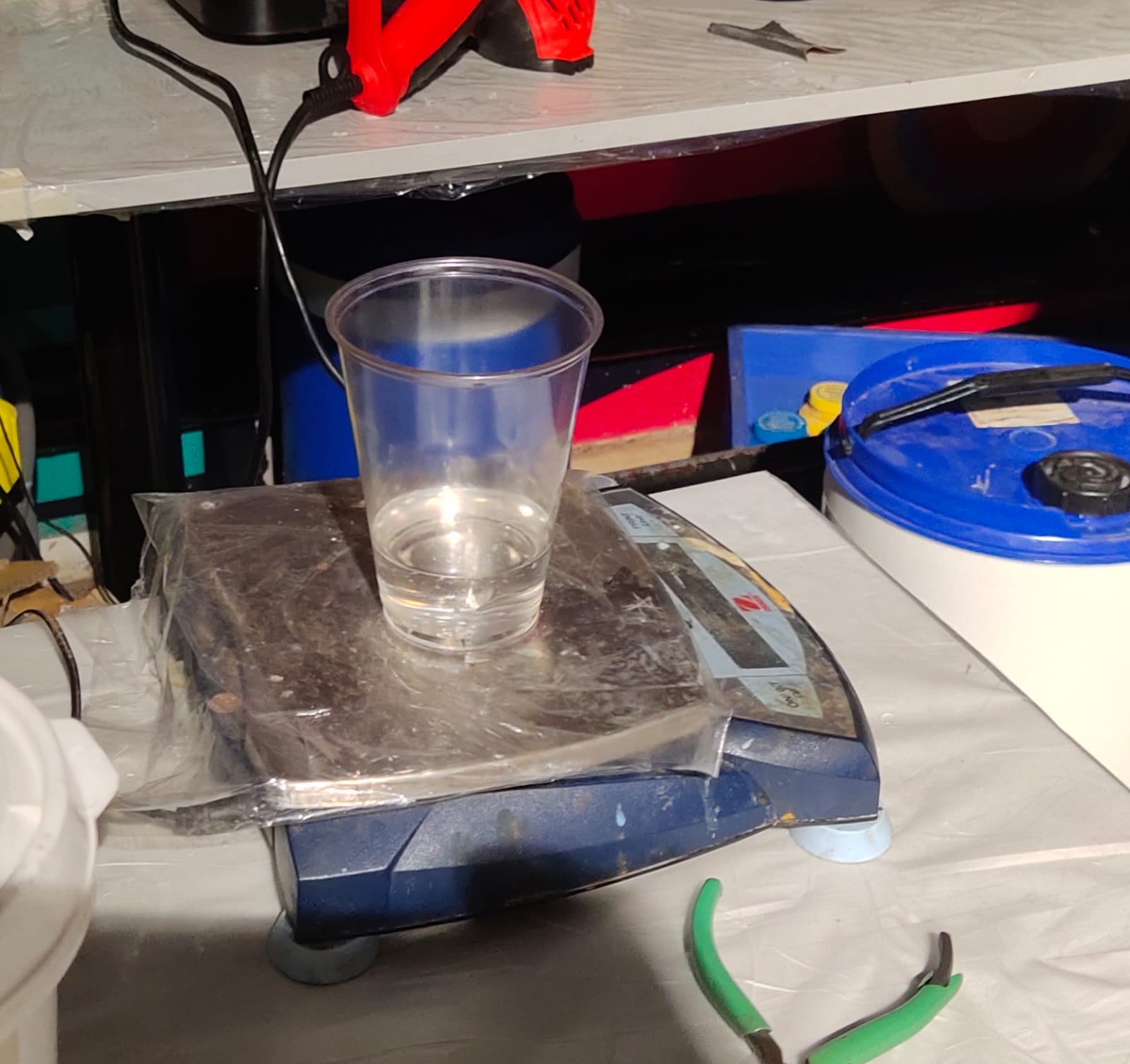
Now take the previously used transparent glass and remove the water content by using an air blower.
🚨
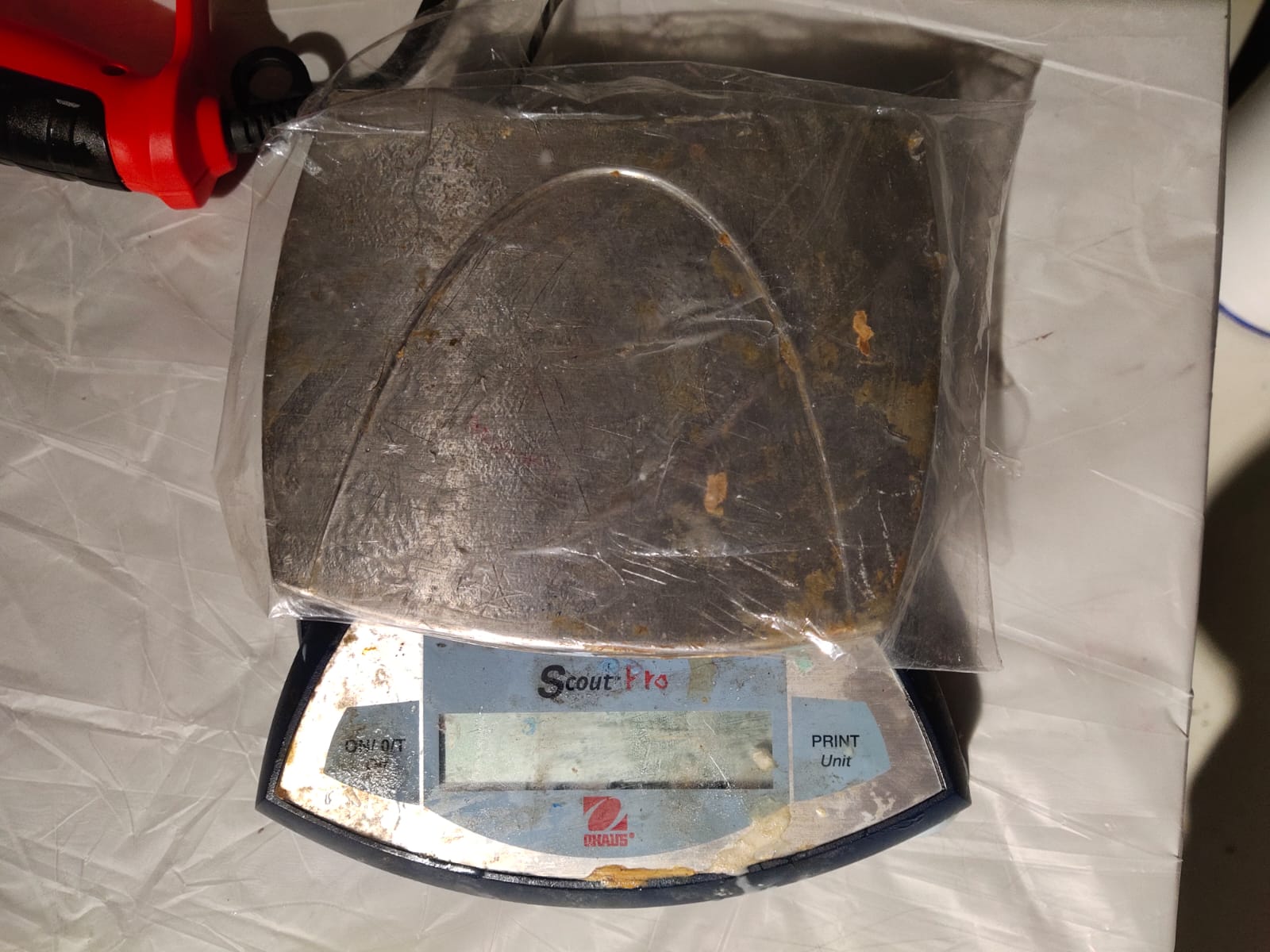
Place the glass on a weighing machine and make sure to set the weighing machine again to zero.
🚨
Pour the silicone into the glass up to the marked level.
💠
It is recommended to take a few extra silicone because a small amount of silicone will be lost by sticking to the glass.
💠
Now note the value of the silicone and calculate the amount of curing agent that needs to be added.
🚨
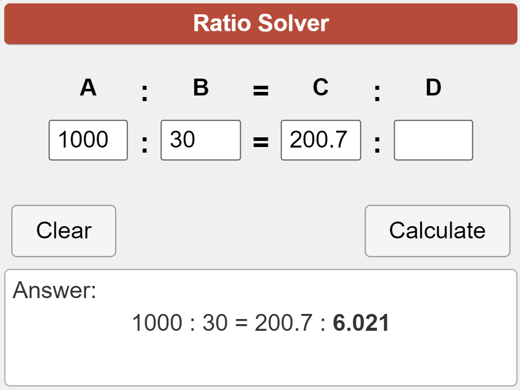
I got 200.7 g as the weight of the silicone.
🚨
The amount of curing agent will be = ( 200.7 x 3)/100 =6.021
Make sure the mold is free of air bubbles, water, and dust before adding the silicone by cleaning the mold with the air blower.
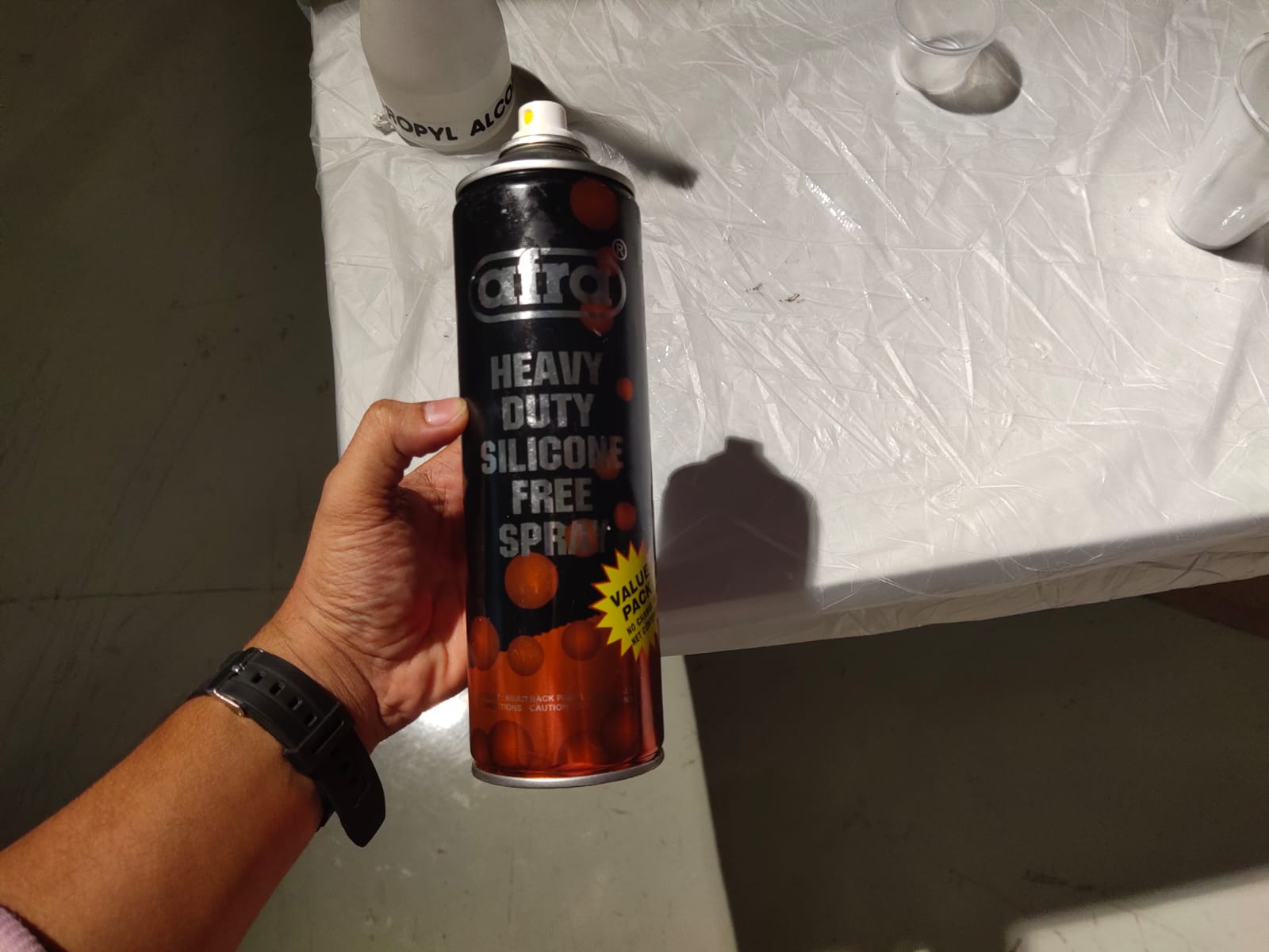
🚨
Then spray the silicone-free spray on top of the mold so that the silicone can be easily removed from the mold when it is cured.
🚨
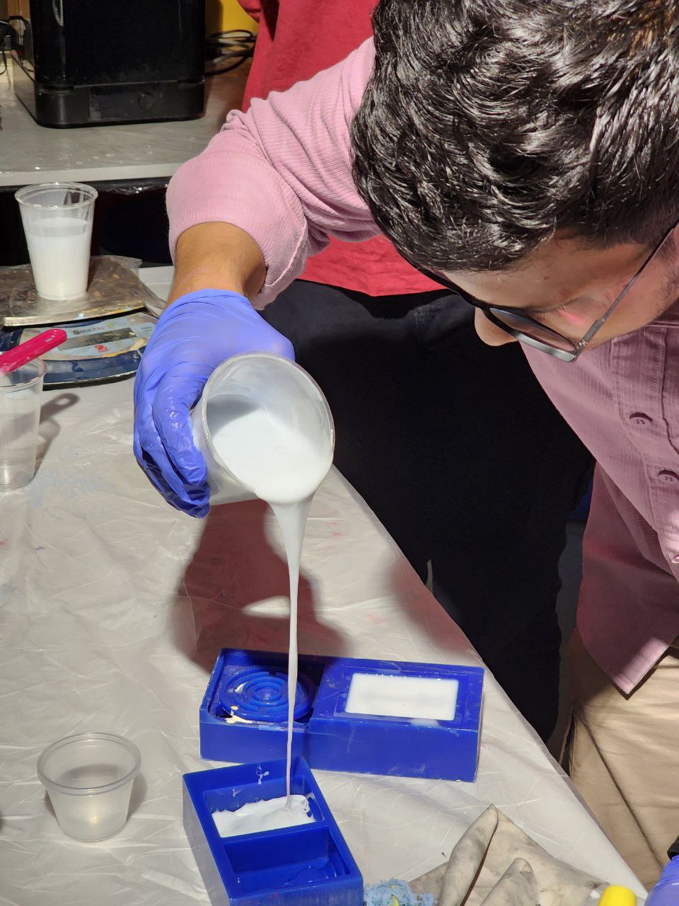
While pouring the silicone, make sure to pour slowly and fill the corners and holes.
🚨
Gently tap the silicone mold on the table to remove the air bubbles from the silicone.
🚨
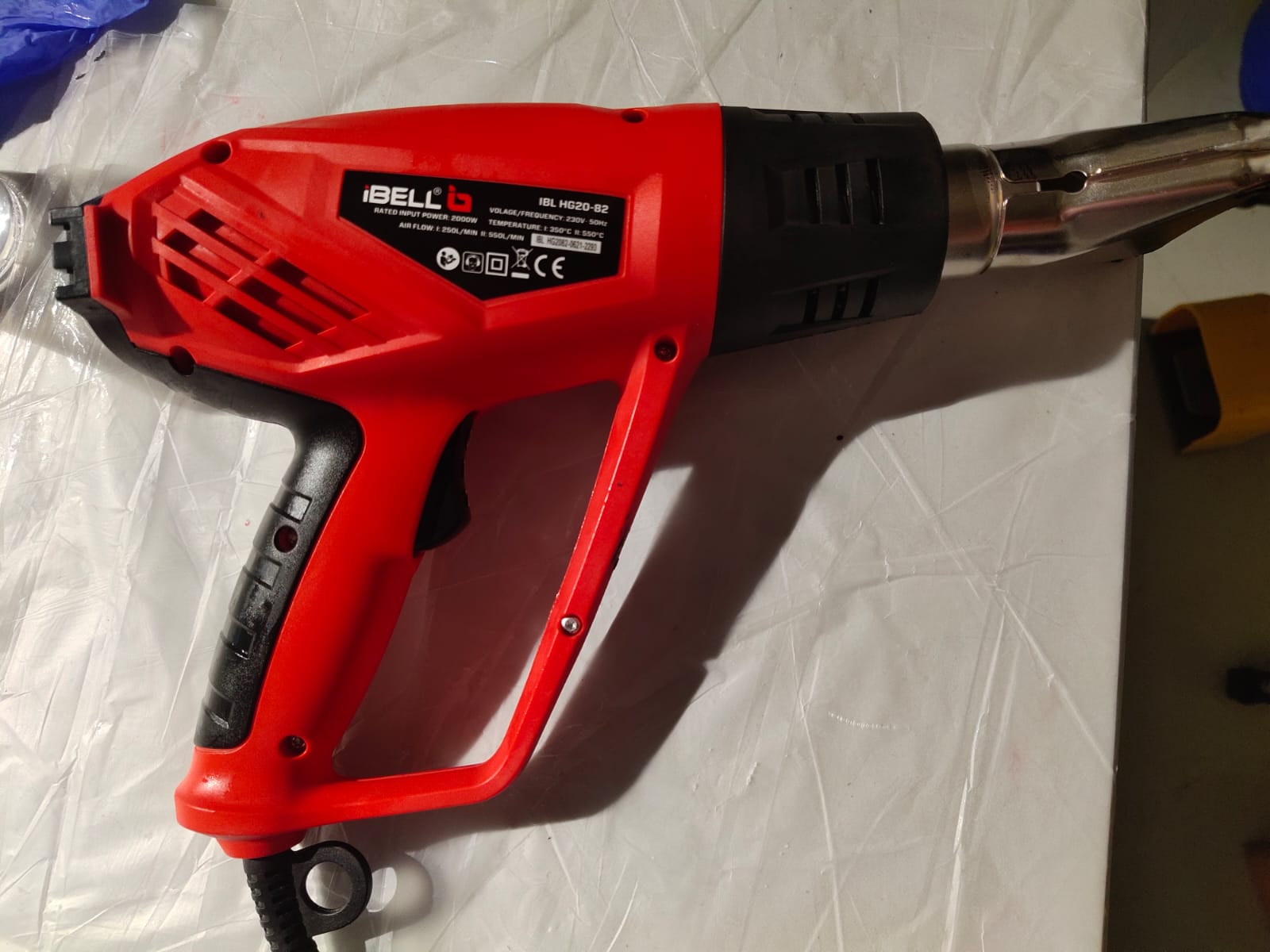
Once you have completely poured the silicone into the mold, use the hot air gun to eliminate the air bubbles.
🚨
I placed my mold in a safe place, and it takes around 24 hours to get cured.
🚨
The time laps of the silicone mold casting is provided below.
😃
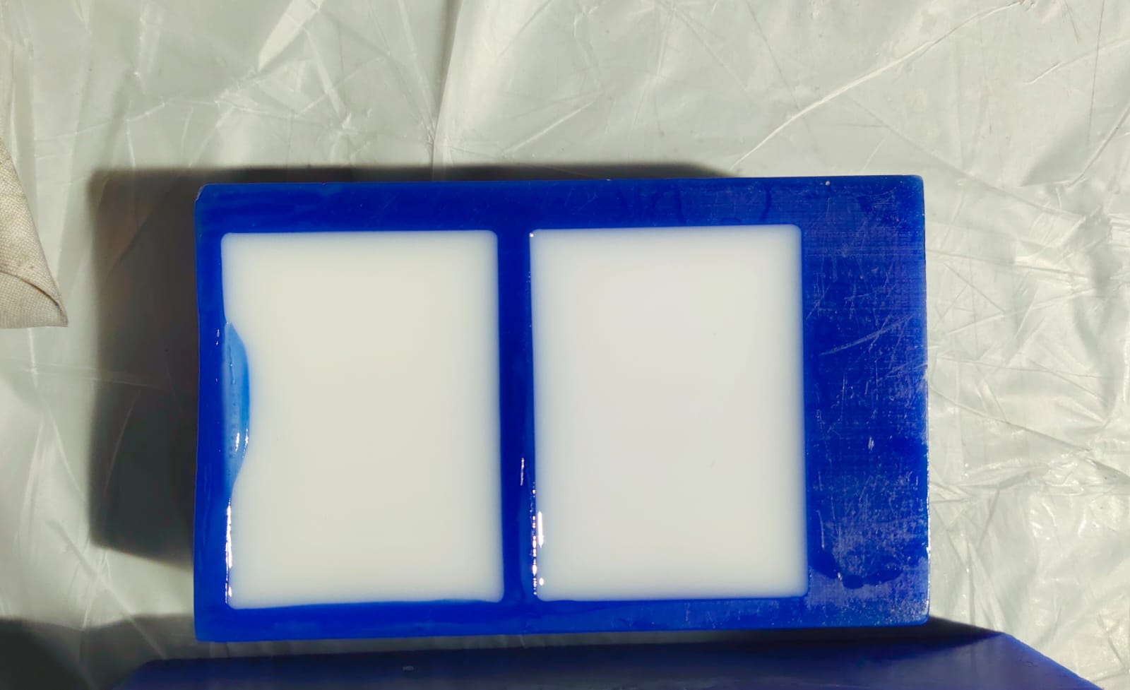
After 24 hours, I got the perfect result.
Casting
Casting is a manufacturing process used to produce solid objects by pouring a liquid material, such as molten metal, plastic, or ceramic, into a mold cavity, which contains a hollow cavity of the desired shape. Once the material solidifies, the mold is removed, and the finished part or object is retrieved.
Types of Casting Processes
Sand Casting
• One of the most common casting methods where a sand mold is used to create the mold cavity. • Suitable for both ferrous and non-ferrous metals and can produce complex shapes with high accuracy.
Investment Casting (or Lost Wax Casting)
• Involves creating a wax pattern, which is then coated with a ceramic shell to form the mold. • After the mold is heated, the wax melts and is removed, leaving a cavity that is filled with molten metal.
Die Casting
• A metal casting process that uses a mold, called a die, into which molten metal is injected under high pressure. • Commonly used for producing high-volume, precision parts with excellent dimensional accuracy and surface finish.
Permanent Mold Casting
• Utilizes reusable metal molds, typically made of steel or cast iron, to produce multiple castings. • The mold can be heated to prolong its life and improve the casting quality.
Centrifugal Casting
• Involves rotating the mold at high speeds while pouring the molten material, causing the material to be pushed towards the mold's outer walls due to centrifugal force. • Used to produce cylindrical or tubular parts with a hollow center.
Resin Casting
Resin casting is a casting process that uses liquid resin materials, typically polyurethane, epoxy, or polyester resins, to produce solid objects. This process involves pouring the liquid resin into a mold cavity, allowing it to cure and solidify, and then demolding the finished part. Resin casting is widely used for creating prototypes, decorative objects, art pieces, and functional components due to its versatility and ability to produce detailed and complex shapes.
Resin Casting Process
Mold Preparation
• A mold is created to form the desired shape of the finished part. • Molds can be made from various materials, such as silicone, latex, or urethane rubber, depending on the application and complexity of the part.
Resin Mixing
• The liquid resin is mixed with a hardener or catalyst according to the manufacturer's instructions. • Pigments, fillers, or additives can be added to the resin mixture to achieve specific colors, properties, or effects.
Pouring
• The mixed resin is carefully poured into the mold cavity. • Vacuum or pressure casting techniques can be used to remove air bubbles from the resin and ensure a complete fill of the mold for high-quality parts.
Curing
• The resin is left to cure and solidify inside the mold. • The curing time varies depending on the type of resin, its thickness, and ambient temperature. It can range from a few minutes to several hours or even days for some specialized resins.
Demolding
• Once the resin has fully cured, the mold is opened, and the solidified casting is removed. • Care must be taken during demolding to prevent damage to the part or the mold.
Post-Processing
• The casting may require additional finishing processes, such as sanding, trimming, polishing, or painting, to achieve the desired surface finish and appearance. • Clear resin castings may benefit from UV curing to enhance clarity and hardness.
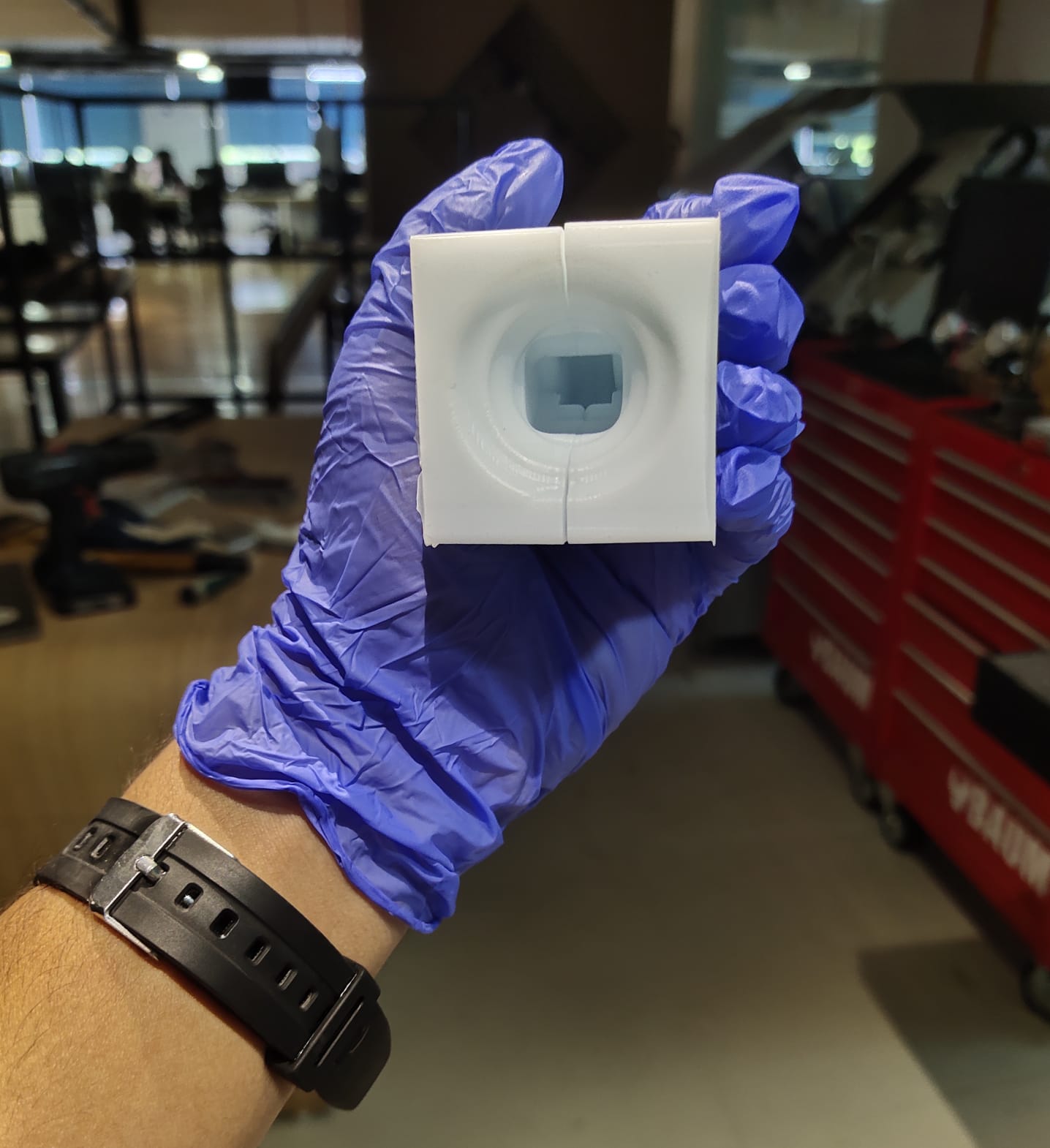
🚨
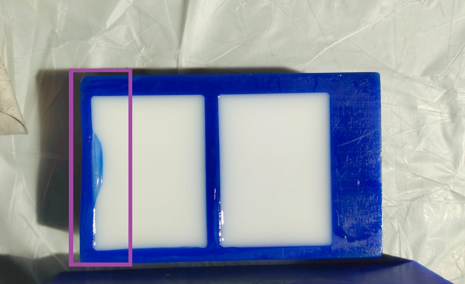
The image below illustrates the silicone mold after cured.
🚨
After using water to clean the mold, I added water to measure its volume and see whether any leaks were present.
🚨
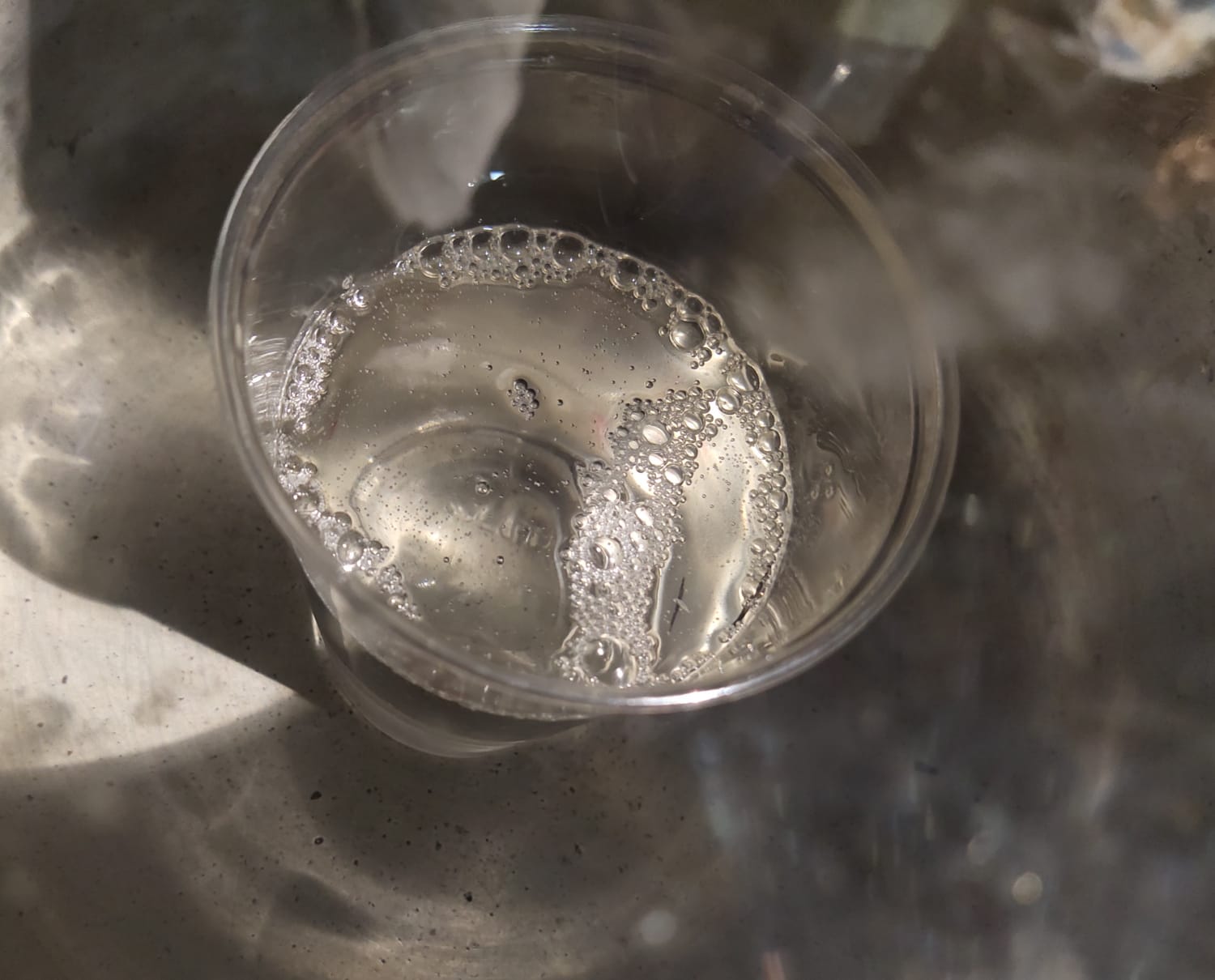
To get the volume, I poured the water into a disposable transparent glass and marked the level. I considered adding a little extra water while measuring the volume.
🚨
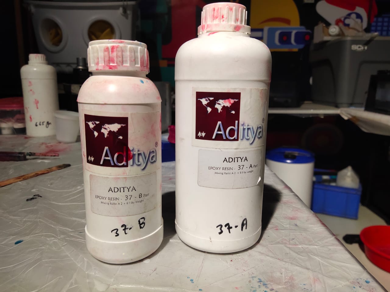
Aditya epoxy resin is the resin we use in our lab.
🚨
Epoxy resin comes in two parts: part A and part B. A2+B is the stated mixing ratio.
🧮
After mixing both parts, I need to get the volume which I marked on the glass. The amount of part A and part B resin is unknown to me. I considered amount of part B resin as X, so part A will be 2X.
🧮
Total weight = 2X + X= 3X
🧮
To get an approximate value I decided to take the total weight of the water instead of resin.
🧮
The volume of the water marked on the glass consists of the volume of the water of my peers.
🧮
So the total weight I got was 195 g.
🧮
Therefor X = 65. I added 130 g of part A and 65 g of part B and mixed properly.
🚨
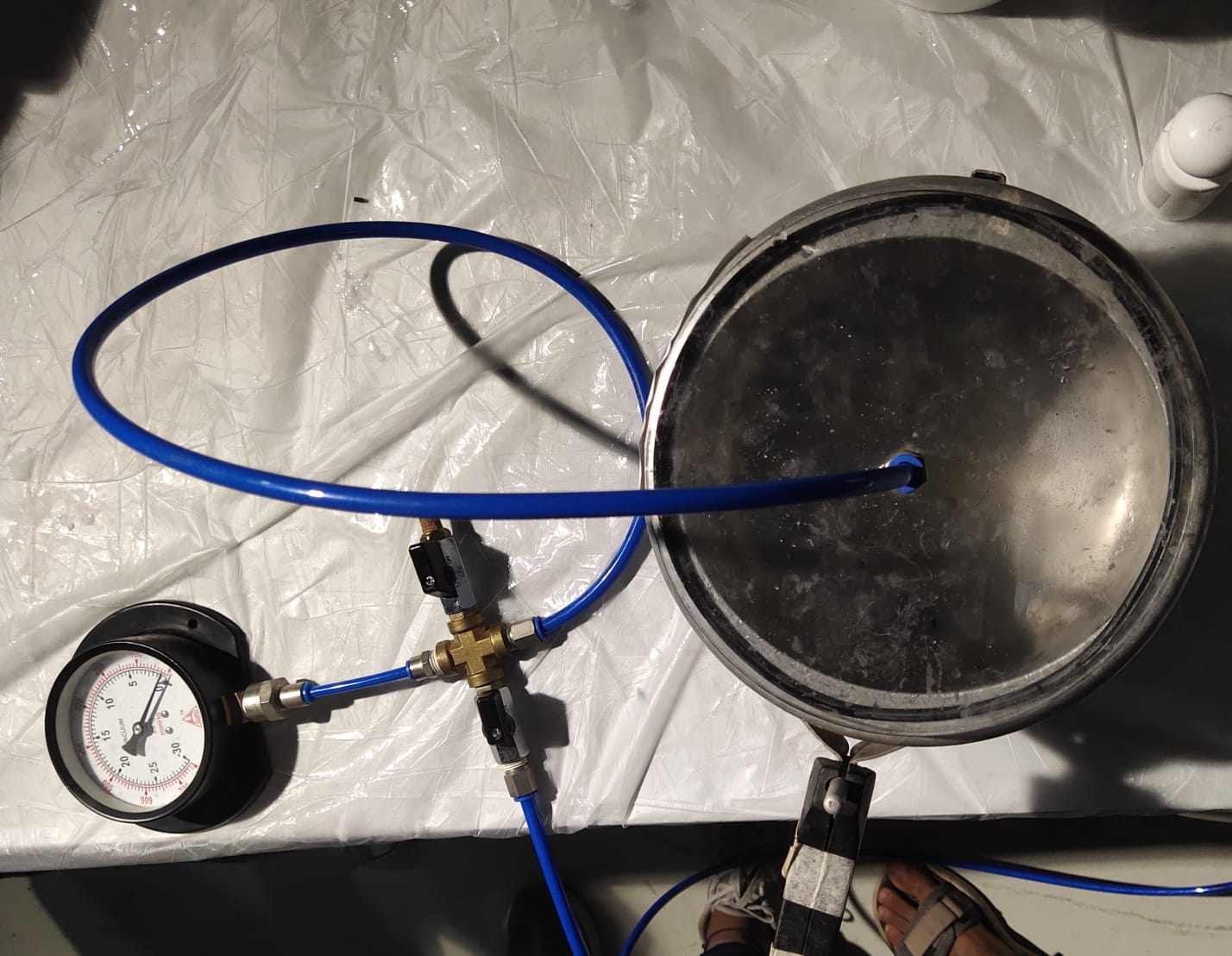
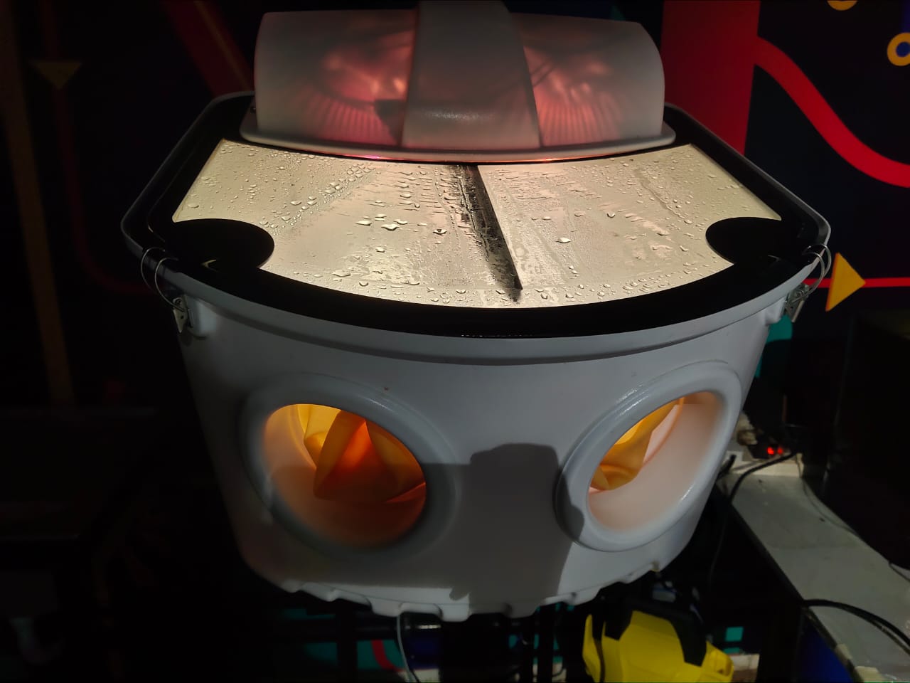
To remove the air bubbles from the resin my instructor recommended us to try out using the vacuum chamber.
🚨
The image below illustrates the mixed resin placed inside the vacuum chamber where the air bubbles are removed from the resin.
🚨
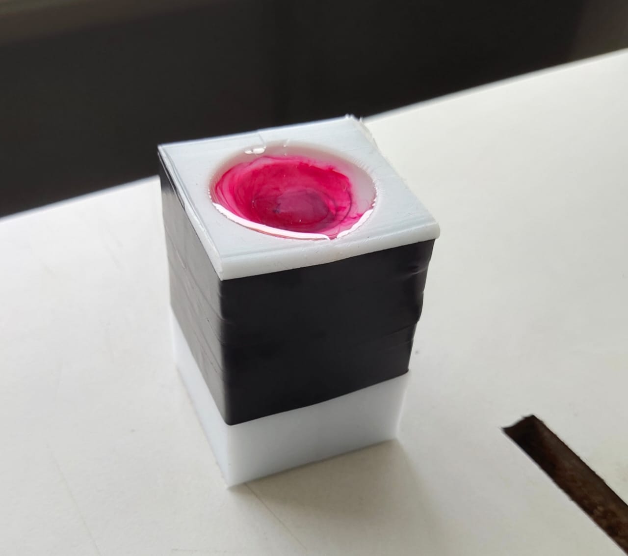
To eliminate the leakage, I used an insulation tap to combine the two molds properly.
🚨
Finally, I poured the resin into the silicone mold. The resin takes around 24 hours to cure.
🚨
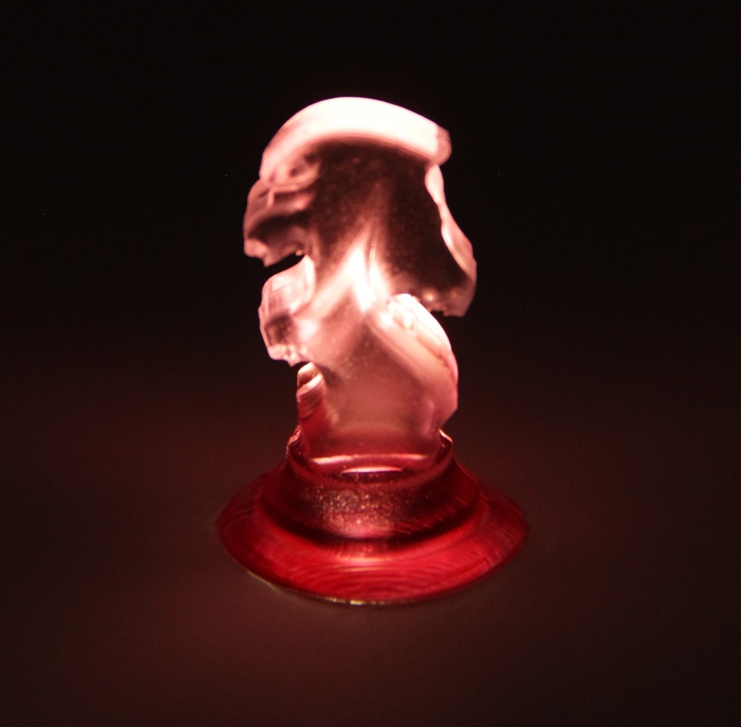
Finally, I got the result 🥹🥹🥹🥹🥹.
🚨
Final Result 🙂
🚨
Final result video ⬇️
Challenges
🚨
I used the hot air gun to remove the air bubbles from the silicone mold, and while heating, I got lost for a few seconds, and a small part of the wax got melted, as shown below.
Ratio Mixing Error
🚨
While calculating the ratio of the curing agent for the silicone mold along with my peers, we were doing mental calculations, and instead of dividing it by 100, we divided it by 1000. The curing agent was not enough, and after 24 hours, the silicone did not get cured. So I had to mix the silicone again.


 https://www.autodesk.com/products/fusion-360/blog/computer-aided-manufacturing-beginners/
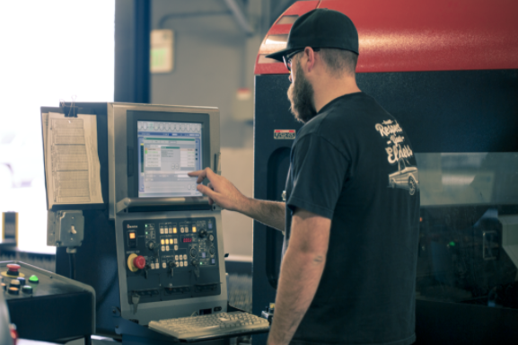


 https://www.calculatorsoup.com/calculators/math/ratios.php