Individual Assignment
Group Assignment
Table of Contents
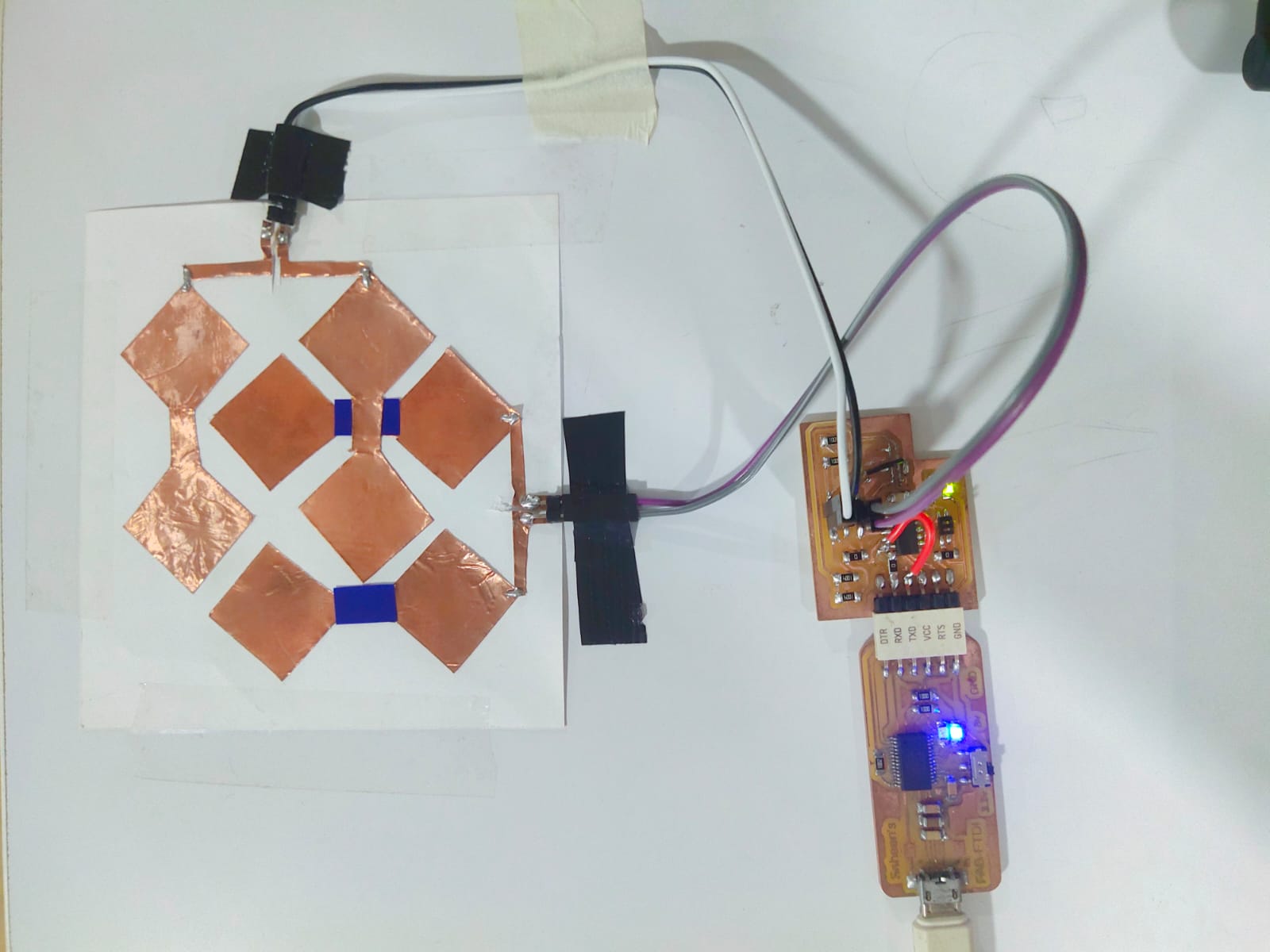
Hero Shot
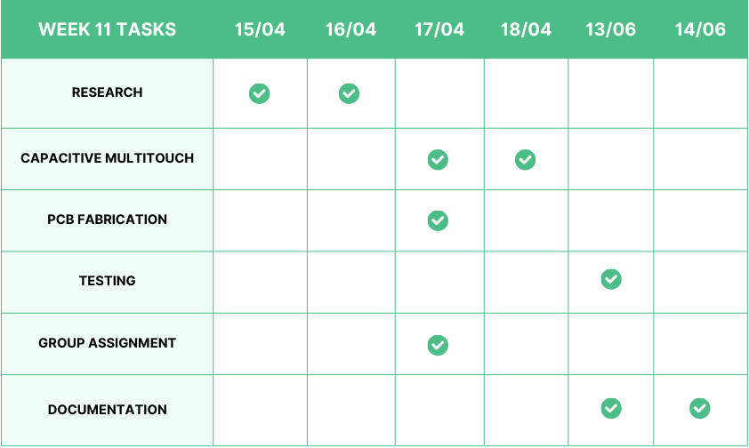
Week 11 Work Plan
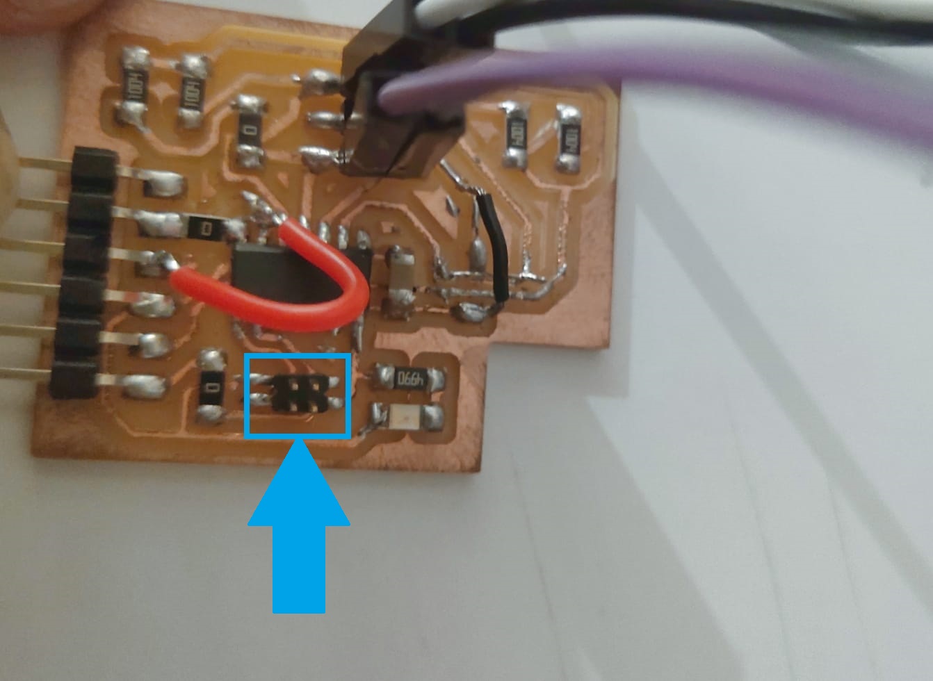
Step Response
The step response of a system is the output behavior of a system when subjected to a step input. A step input is a type of input signal that changes from one value to another, typically from zero to a constant value, instantaneously at a specified time.
 https://en.wikipedia.org/wiki/Step_response
 https://vimeo.com/933093724
Capacitor
Working Principle
Capacitive Sensing
Working
Types of Capacitive Sensors
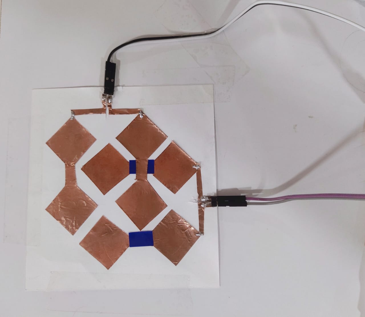
Capacitive Multitouch
Creating a capacitive multitouch sensor involves designing a grid of conductive material to detect multiple touch points simultaneously. This technology is used in modern touchscreens found in smartphones, tablets, and other interactive devices.
Designing a New Board for Capacitive Multitouch
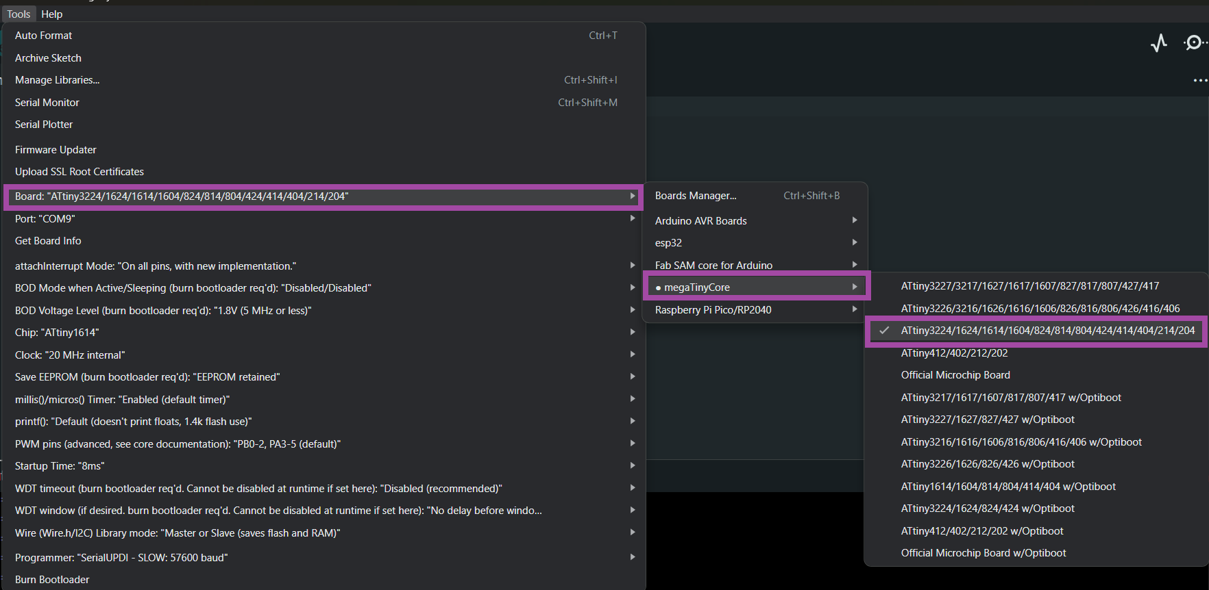
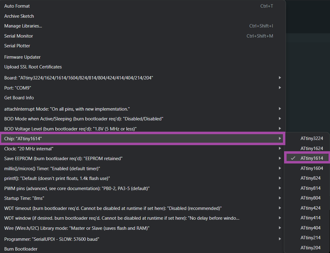
Selecting the Microcontroller
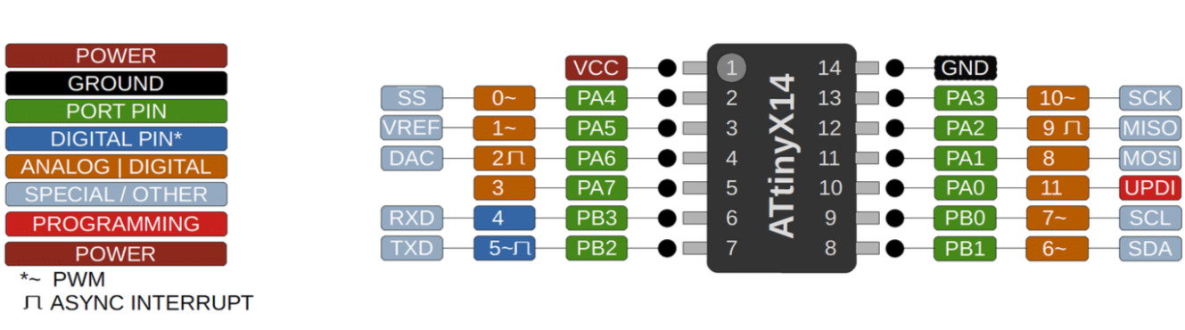
ATtiny1614
The ATtiny1614 is a high-performance, low-power 8-bit AVR RISC-based microcontroller that combines 16KB ISP flash memory, 256B EEPROM, 2KB SRAM, and operates up to 20 MHz. It offers a broad range of features including 18 general purpose I/O lines, 32 general purpose working registers, three flexible timer/counters with compare modes, internal and external interrupts, a serial programmable USART, a byte-oriented 2-wire serial interface, a 10-bit ADC with 10 channels, a programmable watchdog timer with internal oscillator, and five software-selectable power saving modes.
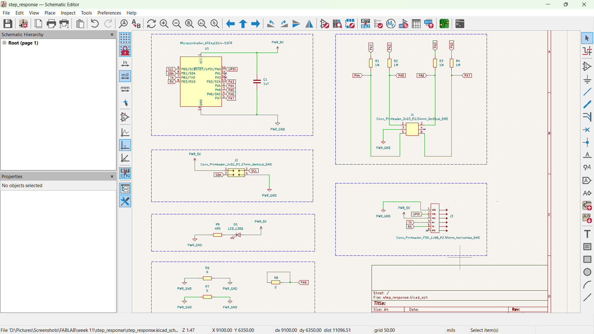
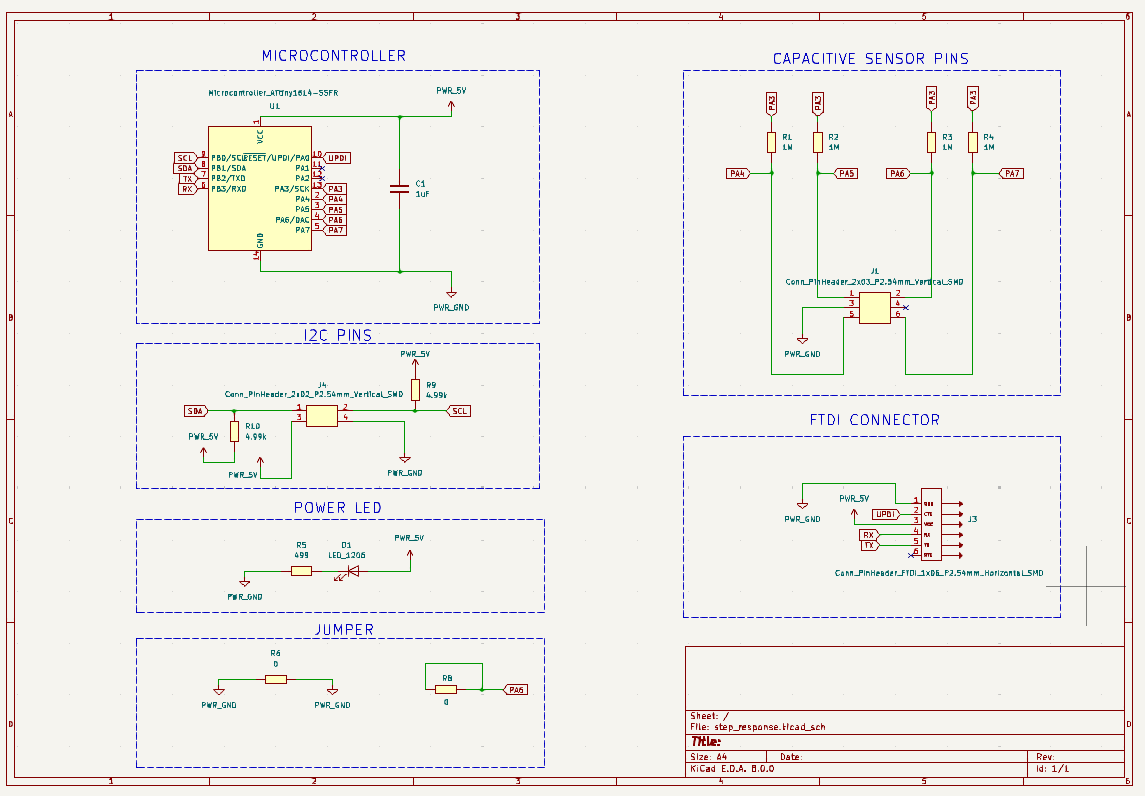
Schematic in KiCad
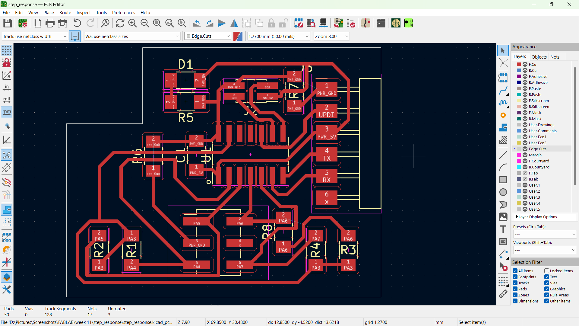
PCB Routing in KiCad
Converting Gerber file to PNG
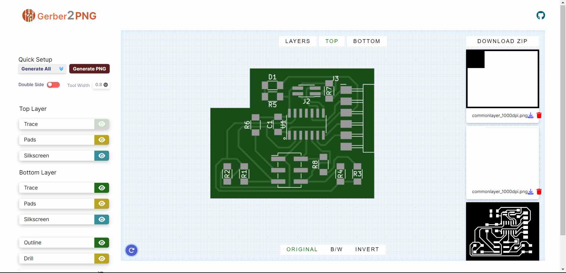
 https://gerber2png.fablabkerala.in/
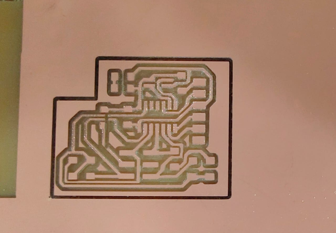
PCB Milling
PCB Soldering
Bill of Materials
| Reference | Value | Qty | Datasheet |
| C1 | 1uF | 1 | https://www.yageo.com/upload/media/product/productsearch/datasheet/mlcc/UPY-GP_NP0_16V-to-50V_18.pdf |
| D1 | LED_1206 | 1 | https://optoelectronics.liteon.com/upload/download/DS-22-98-0002/LTST-C150CKT.pdf |
| J1 | Conn_PinHeader_2x03_P2.54mm_Vertical_SMD | 1 | https://cdn.amphenol-icc.com/media/wysiwyg/files/drawing/95278.pdf |
| J2 | Conn_PinHeader_2x02_P1.27mm_Vertical_SMD | 1 | https://s3.amazonaws.com/catalogspreads-pdf/PAGE94-95%20.050%20MALE%20HDR%20ST%20RA%20SMT.pdf |
| J3 | Conn_PinHeader_FTDI_1x06_P2.54mm_Horizontal_SMD | 1 | ~ |
| R1,R2,R3,R4 | 1M | 4 | ~ |
| R5 | 499 | 1 | ~ |
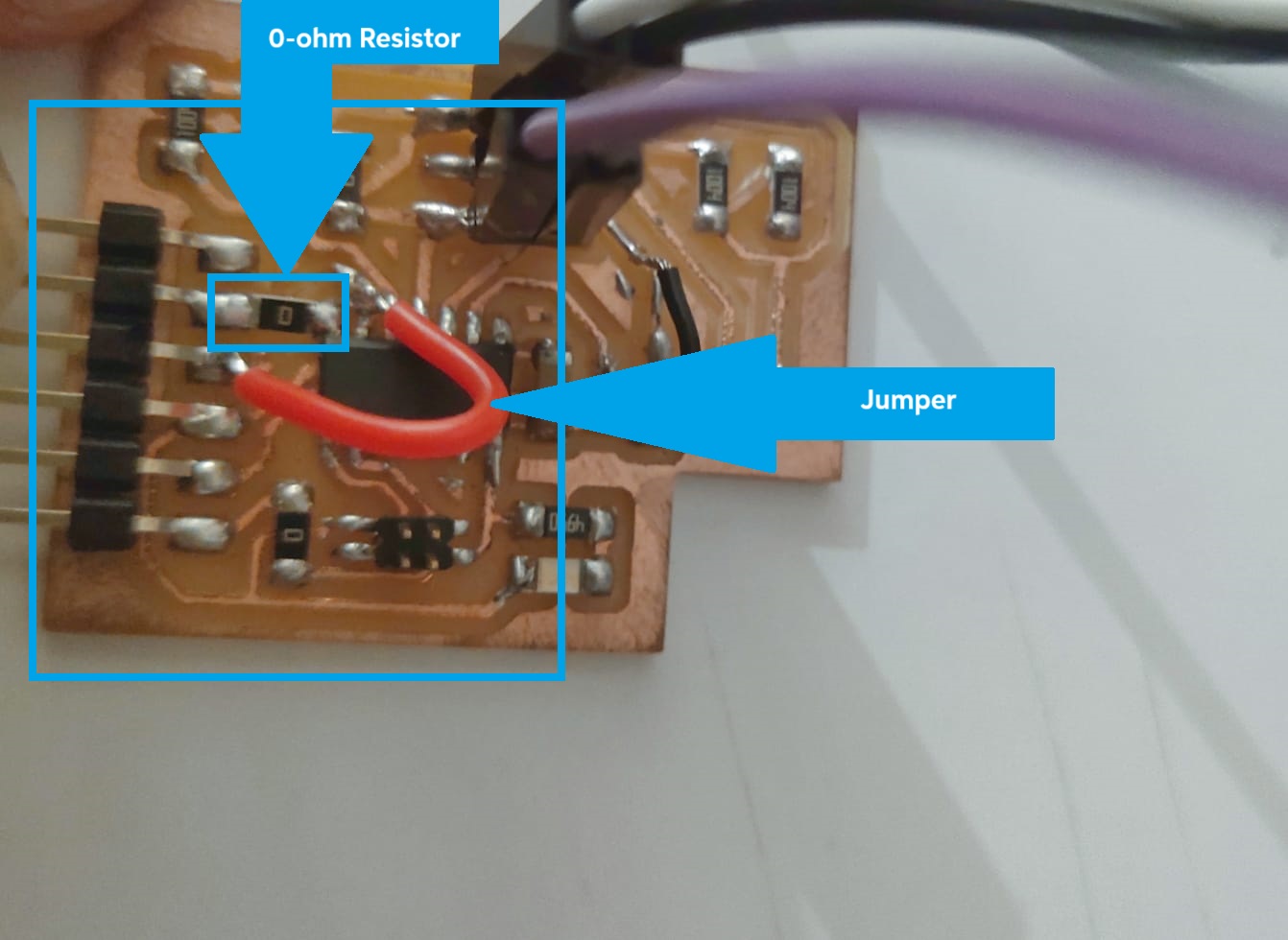
| R6,R7,R8 | 0 | 3 | ~ |
| U1 | Microcontroller_ATtiny1614-SSFR | 1 | http://ww1.microchip.com/downloads/en/DeviceDoc/ATtiny1614-16-17-DataSheet-DS40002204A.pdf |
Interactive BOM
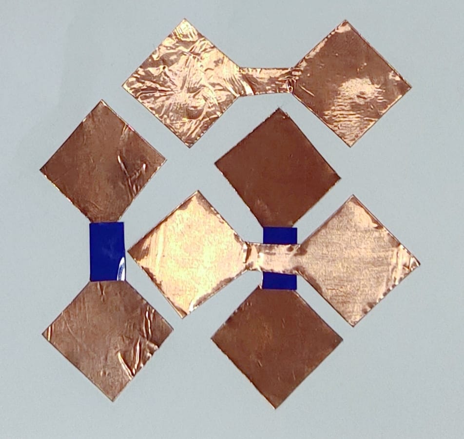
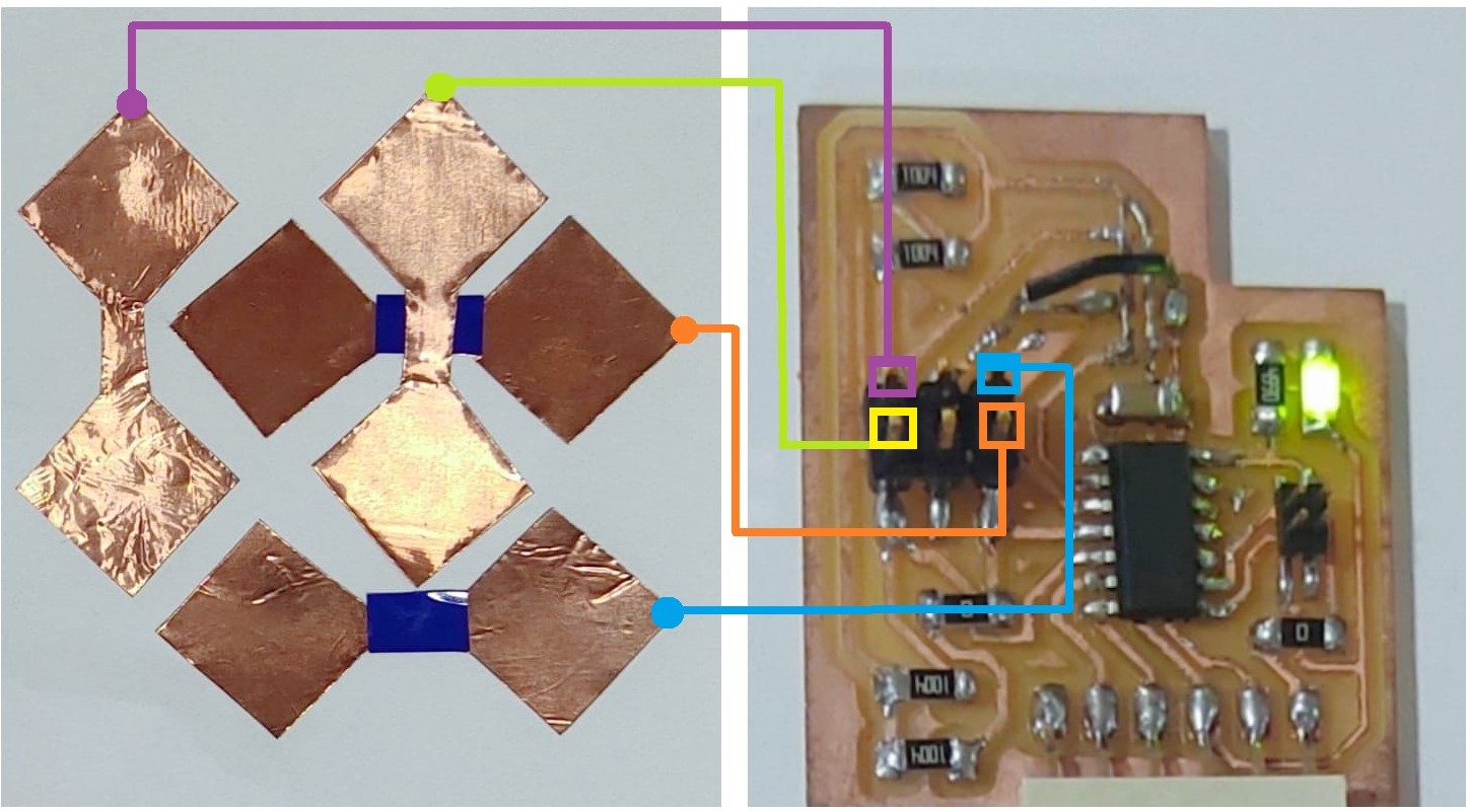
Touchpad Design
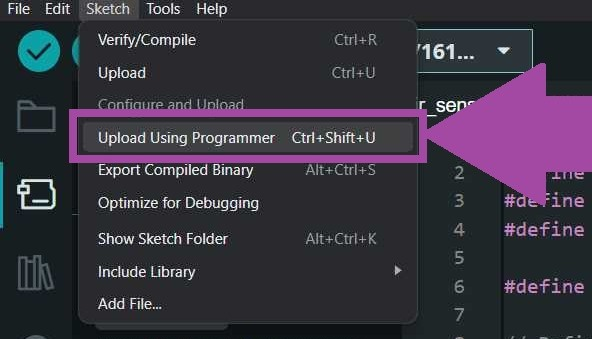
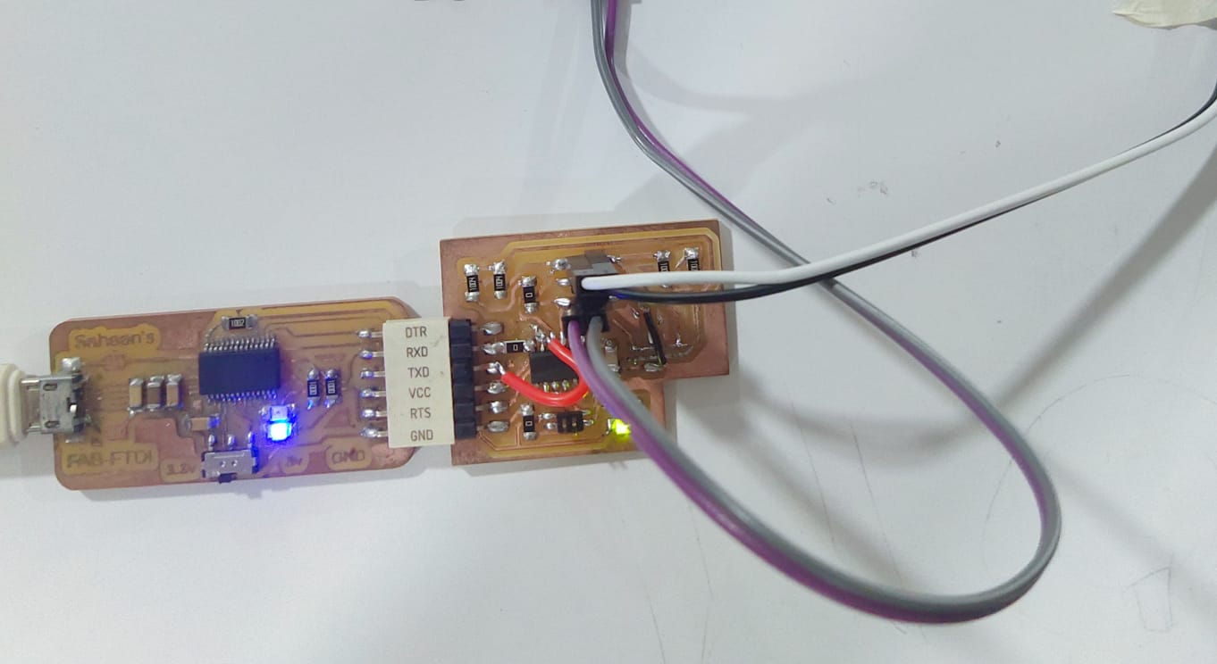
Programming the Board
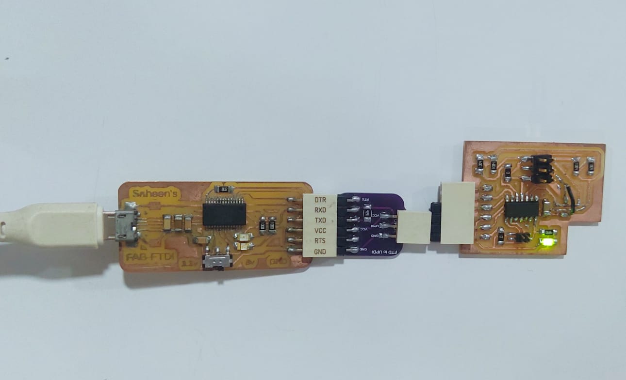
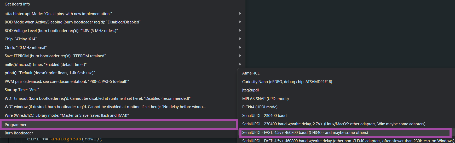
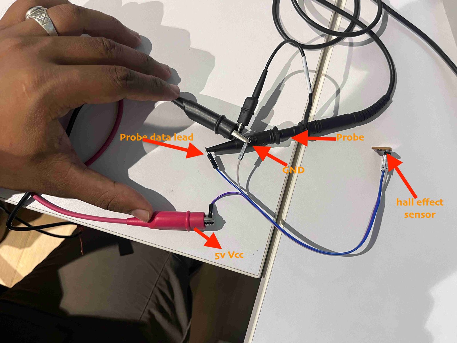
Access Data Serially
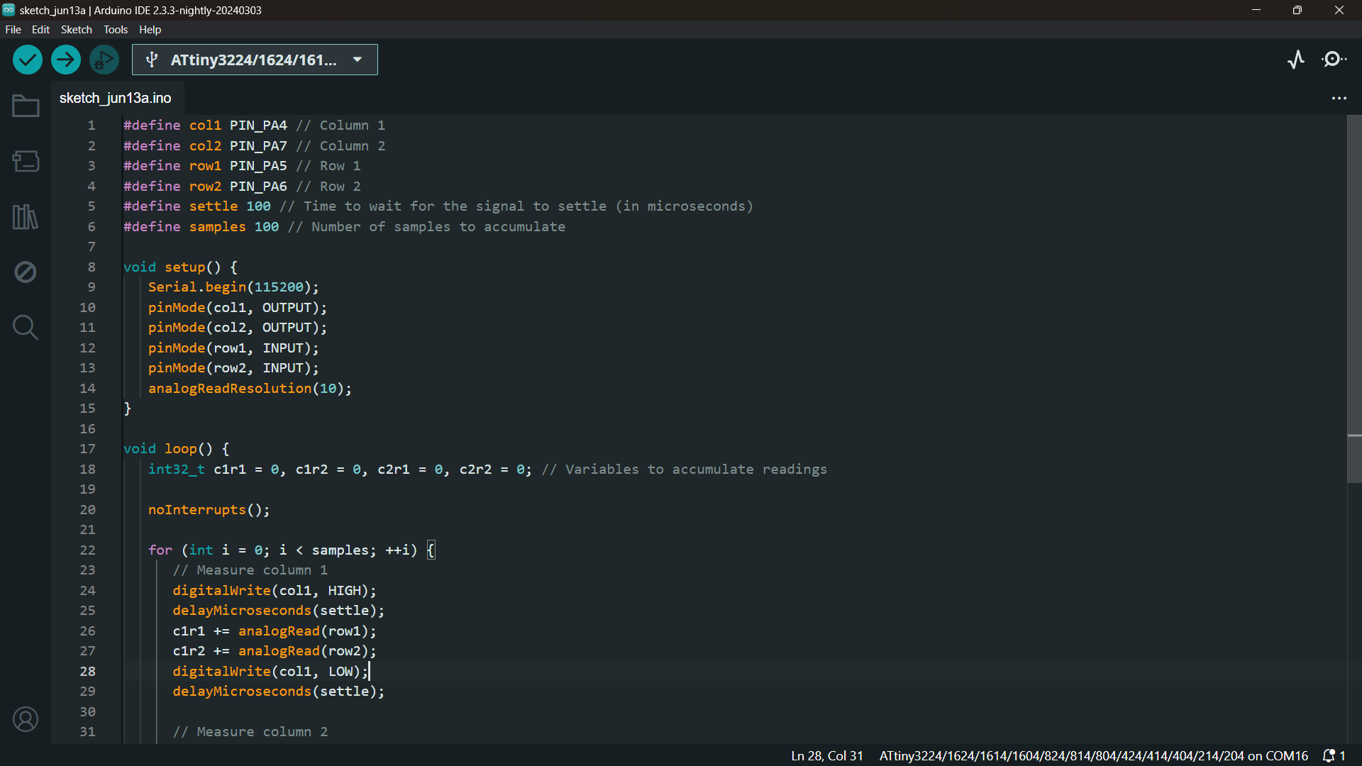
Embedded Program
// Define pin assignments for columns and rows
#define col1 PIN_PA4 // Column 1
#define col2 PIN_PA7 // Column 2
#define row1 PIN_PA5 // Row 1
#define row2 PIN_PA6 // Row 2

// Define constants for signal settling time and number of samples
#define settle 100 // Time to wait for the signal to settle (in microseconds)
#define samples 100 // Number of samples to accumulate

void setup() {
   Serial.begin(115200); // Initialize serial communication at 115200 baud rate
   pinMode(col1, OUTPUT); // Set column 1 pin as output
   pinMode(col2, OUTPUT); // Set column 2 pin as output
   pinMode(row1, INPUT); // Set row 1 pin as input
   pinMode(row2, INPUT); // Set row 2 pin as input
   analogReadResolution(10); // Set analog read resolution to 10 bits
}

void loop() {
   // Initialize variables to accumulate readings for each column-row combination
   int32_t c1r1 = 0, c1r2 = 0, c2r1 = 0, c2r2 = 0;

   noInterrupts(); // Disable interrupts to ensure accurate timing for measurements

   for (int i = 0; i < samples; ++i) {
      // Measure signals for column 1
      digitalWrite(col1, HIGH); // Set column 1 HIGH
      delayMicroseconds(settle); // Wait for the signal to settle
      c1r1 += analogRead(row1); // Read analog value from row 1 and accumulate
      c1r2 += analogRead(row2); // Read analog value from row 2 and accumulate
      digitalWrite(col1, LOW); // Set column 1 LOW
      delayMicroseconds(settle); // Wait for the signal to settle

      // Measure signals for column 2
      digitalWrite(col2, HIGH); // Set column 2 HIGH
      delayMicroseconds(settle); // Wait for the signal to settle
      c2r1 += analogRead(row1); // Read analog value from row 1 and accumulate
      c2r2 += analogRead(row2); // Read analog value from row 2 and accumulate
      digitalWrite(col2, LOW); // Set column 2 LOW
      delayMicroseconds(settle); // Wait for the signal to settle
   }

   interrupts(); // Re-enable interrupts

   // Print the accumulated readings for each column-row combination
   Serial.print("C1R1: ");
   Serial.print(c1r1);
   Serial.print(", C1R2: ");
   Serial.print(c1r2);
   Serial.print(", C2R1: ");
   Serial.print(c2r1);
   Serial.print(", C2R2: ");
   Serial.println(c2r2);

   Serial.flush(); // Ensure all serial data is transmitted before continuing
}
⚠️ Calibrate the Sensor
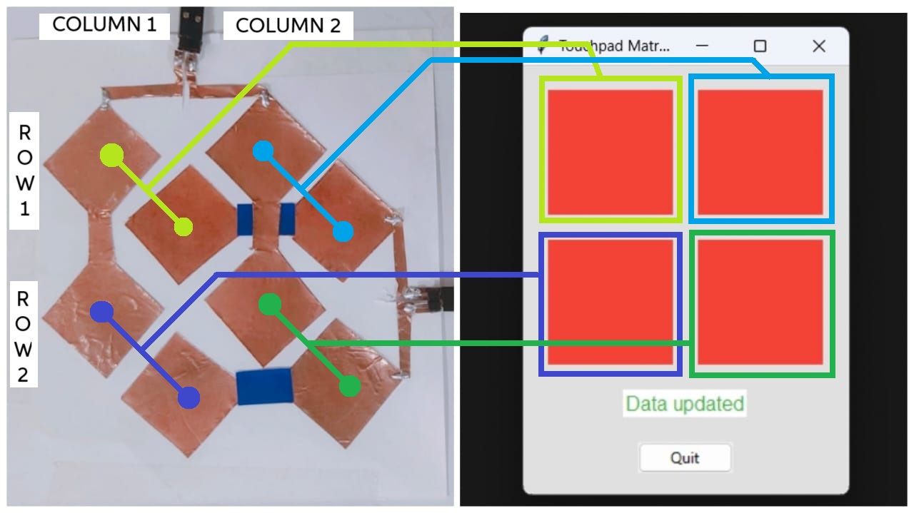
Creating the GUI for the Capacitive Multitouch Pad
Overview of the Implementation
GUI Code
import tkinter as tk
from tkinter import ttk
import serial
import threading
# Define the serial port and baud rate
SERIAL_PORT = 'COM17'
BAUD_RATE = 115200
# Class to handle serial communication
class SerialReader:
def __init__(self, port, baudrate):
# Initialize the serial port
self.serial_port = serial.Serial(port, baudrate, timeout=1)
self.is_running = False
self.thread = None
def start_reading(self, callback):
# Start the thread to read serial data
self.is_running = True
self.thread = threading.Thread(target=self.read_serial, args=(callback,))
self.thread.start()
def stop_reading(self):
# Stop the thread reading serial data
self.is_running = False
if self.thread is not None:
self.thread.join()
def read_serial(self, callback):
# Continuously read from the serial port and call the callback with the data
while self.is_running:
if self.serial_port.in_waiting > 0:
data = self.serial_port.readline().decode().strip()
if data:
callback(data)
def close(self):
# Close the serial port
self.serial_port.close()
# Custom frame to represent a color-changing rectangle
class RectangleLabel(ttk.Frame):
def __init__(self, parent, width=50, height=50, bg="red", **kwargs):
super().__init__(parent, **kwargs)
self.width = width
self.height = height
self.bg = bg
# Create a canvas to draw the rectangle
self.canvas = tk.Canvas(self, width=self.width, height=self.height, bg=self.bg, highlightthickness=0)
self.canvas.pack(fill=tk.BOTH, expand=True)
def set_color(self, color):
# Change the color of the rectangle
self.canvas.config(bg=color)
# Main application class
class App:
def __init__(self, root):
self.root = root
self.root.title("Touchpad Matrix GUI")
self.root.geometry("500x500") # Set square size of the window
# Configure styles for better appearance
self.style = ttk.Style()
self.style.configure('TFrame', background='#e0e0e0') # Set background color for frames
self.style.configure('TLabel', background='#ffffff', foreground='#333333', font=('Arial', 12)) # Set label styles
self.style.map('TButton', background=[('active', '#ffc107')]) # Button color change on click
# Initialize the serial reader
self.serial_reader = SerialReader(SERIAL_PORT, BAUD_RATE)
self.create_widgets()
# Start reading from the serial port
self.serial_reader.start_reading(self.update_display)
def create_widgets(self):
# Create a frame to hold the widgets
self.frame = ttk.Frame(self.root, padding="10")
self.frame.grid(row=0, column=0, sticky=(tk.W, tk.E, tk.N, tk.S))
# Create rectangle labels for the touchpad matrix
self.c1r1_label = RectangleLabel(self.frame, width=100, height=100, bg="red")
self.c1r1_label.grid(row=0, column=0, padx=10, pady=10)
self.c1r2_label = RectangleLabel(self.frame, width=100, height=100, bg="red")
self.c1r2_label.grid(row=1, column=0, padx=10, pady=10)
self.c2r1_label = RectangleLabel(self.frame, width=100, height=100, bg="red")
self.c2r1_label.grid(row=0, column=1, padx=10, pady=10)
self.c2r2_label = RectangleLabel(self.frame, width=100, height=100, bg="red")
self.c2r2_label.grid(row=1, column=1, padx=10, pady=10)
# Add a status label to show updates
self.status_label = ttk.Label(self.frame, text="Waiting for data...", style='TLabel')
self.status_label.grid(row=2, column=0, columnspan=2, pady=10)
# Add a quit button to close the application
self.quit_button = ttk.Button(self.frame, text="Quit", command=self.quit)
self.quit_button.grid(row=3, column=0, columnspan=2, pady=10)
def update_display(self, data):
try:
# Parse the received data
c1r1, c1r2, c2r1, c2r2 = self.parse_data(data)
# Update the color of the rectangles based on the data
self.update_color(self.c1r1_label, c1r1)
self.update_color(self.c1r2_label, c1r2)
self.update_color(self.c2r1_label, c2r1)
self.update_color(self.c2r2_label, c2r2)
self.status_label.config(text="Data updated", foreground="#4caf50") # Bright green color
except ValueError:
print(f"Failed to parse data: {data}")
self.status_label.config(text="Error: Failed to parse data", foreground="#f44336") # Bright red color
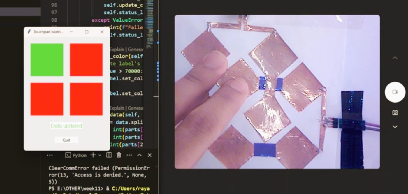
def update_color(self, label, value):
# Update the label's background color based on the value
if value > 70000:
label.set_color("#4caf50") # Bright green color
else:
label.set_color("#f44336") # Bright red color
def parse_data(self, data):
# Parse the received data assuming format "C1R2: value, C1R1: value, C2R2: value, C2R1: value"
parts = data.split(',')
c1r2 = int(parts[0].split(':')[1].strip())
c1r1 = int(parts[1].split(':')[1].strip())
c2r2 = int(parts[2].split(':')[1].strip())
c2r1 = int(parts[3].split(':')[1].strip())
return c1r1, c1r2, c2r1, c2r2
def quit(self):
# Stop reading from the serial port and close the application
self.serial_reader.stop_reading()
self.serial_reader.close()
self.root.destroy()
# Main function to start the application
def main():
root = tk.Tk()
app = App(root)
root.mainloop()
# Entry point of the application
if __name__ == "__main__":
main()
Explanation of the Python Code
Final Result 😀😀😀
Challenges ⚡⚡⚡
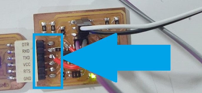
Changed the SMT header pins
Group Assignment Page
Reference
 https://fabacademy.org/2020/labs/barcelona/students/arman-najari/assignments/week10/
Resources and Downloads
📁 GUI Code