Final project
for my final project i am aiming ot create :-
a final project help find a final project / a mkaer proejct idea generator
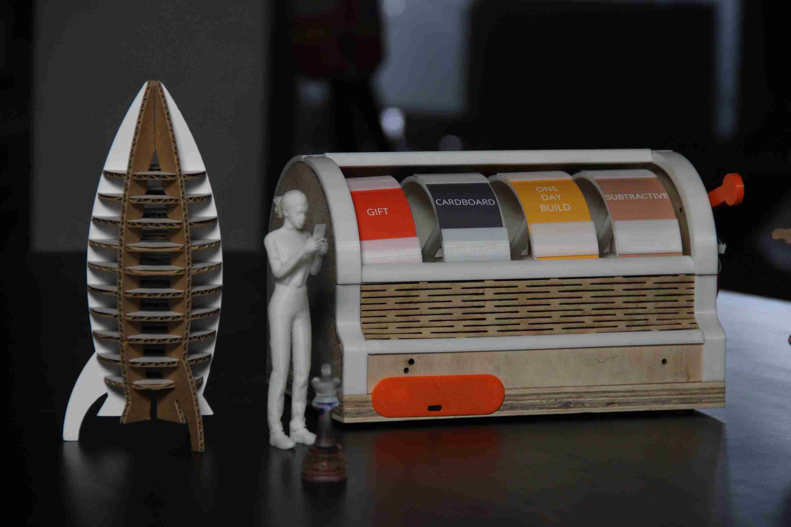
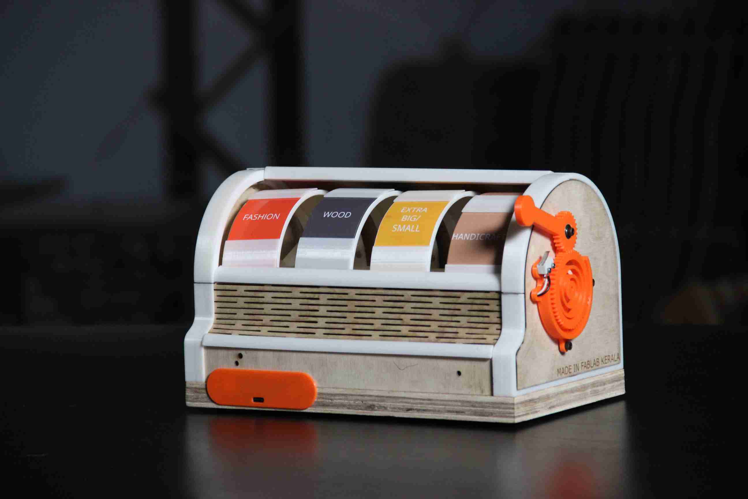
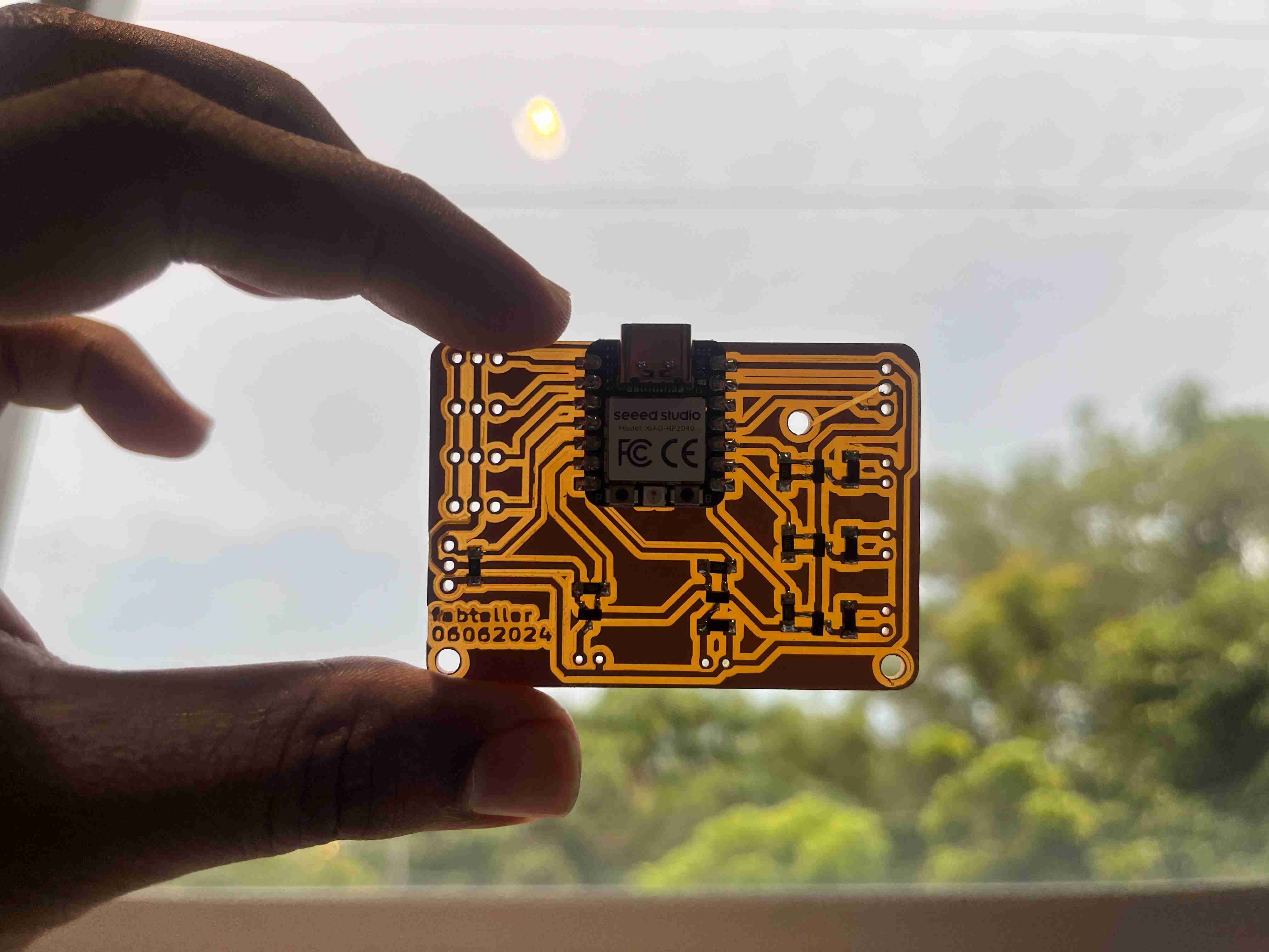
final result

me holding fab teller

project planning
I have couple of ideas for fabacademy final project ideas.
ABOVE ARE SOME OF THE IDEAS I BRAINSTORMED. I REALLY LIKE THE IDEA THAT CAME UP WITH THE FORTURE TELLER THAT "HELP MAKERS IDEATE".SO I AM THINKING ABOUT MAKING A SLOT MACHINE THAT HELP TO IDEATE. yetch made by laura kampf is really inspiring for this idea.
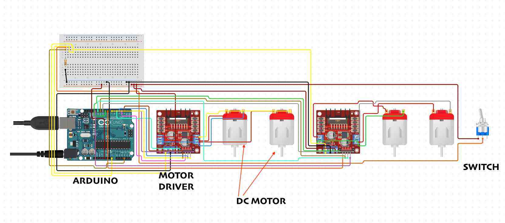
sample circuit i made using ciruit.io
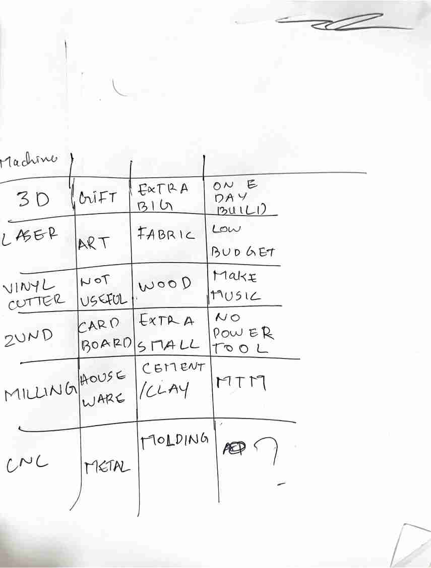
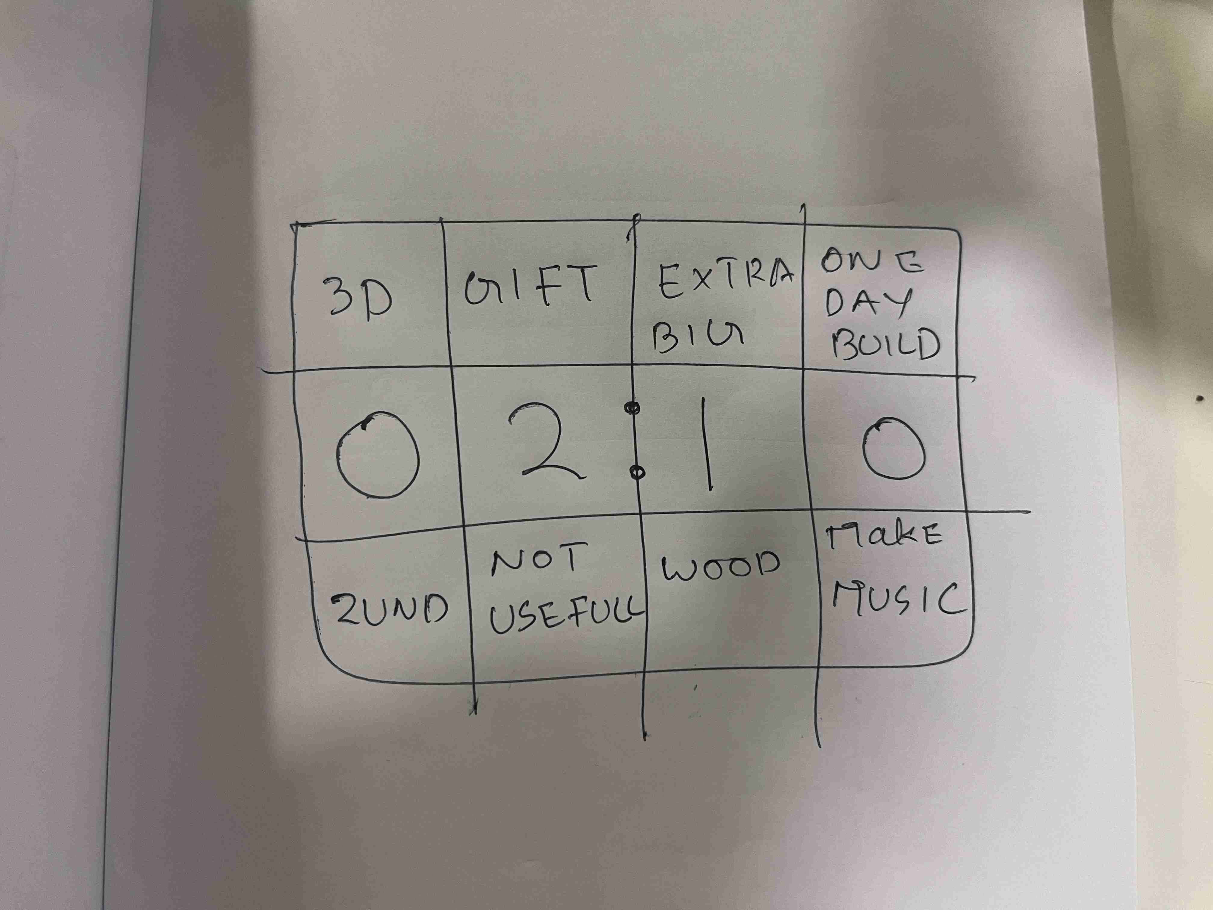
i am brainstoring about what all options i can give the dials.
why can't i add a clock with it. so this could be. a slot machine and clock at the same time.
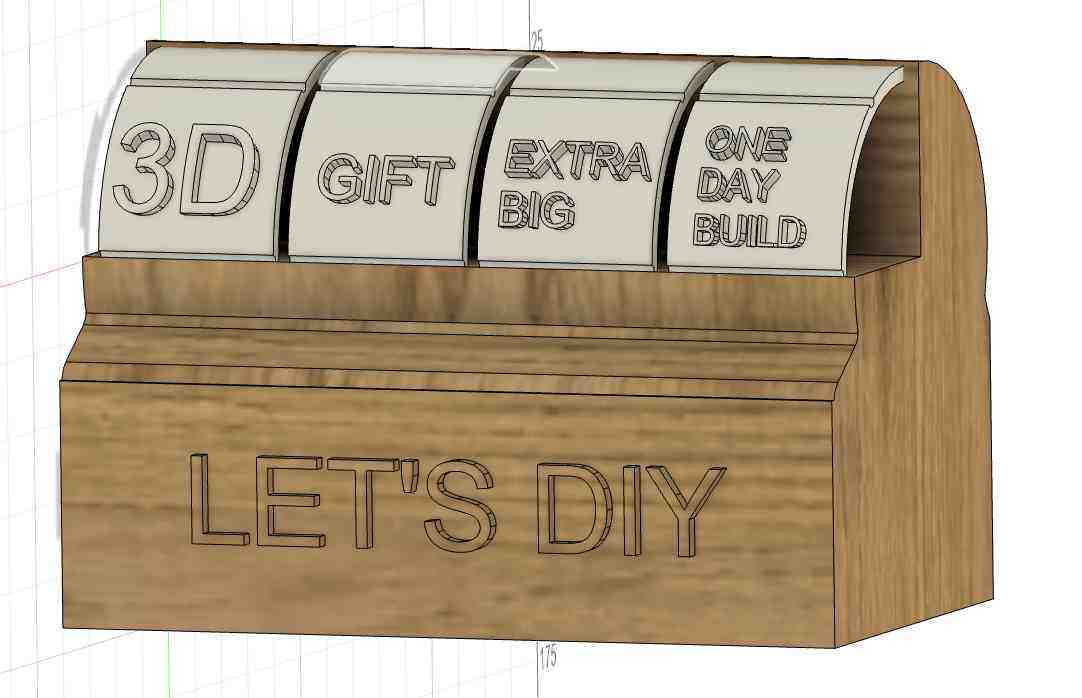
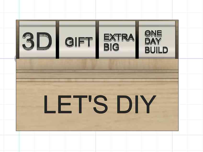
sketch of how the display will look like
content idea
i am PLANNING DIFFERENT combinations i can work on the wheels
Wheel 1: Project Type
- Gift
- Vehicle
- Fashion
- Art
- Tool
- Furniture
Wheel 2: Material
- Cardboard
- Wood
- composite
- Fabric
- Metal
- Recycled Materials
Wheel 3: Constraints/Challenges
- Extra Big/Small
- Not Useful
- Low Budget
- Bio
- Portable
- sustainable
Wheel 4: Fabrication Techniques
- 3D Printing
- Laser Cutting
- Molding/Casting
- Modular Design
- CNC Machining
- Electronics Integration
| Wheel 1: Project Type | Wheel 2: Material | Wheel 3: Constraints/Challenges | Wheel 4: Fabrication Techniques |
|---|---|---|---|
| 1. Gift | 1. Cardboard | 1. Extra Big/Small | 1.additive MANUFACTURING |
| 2. Vehicle | 2. Wood | 2. Not Useful | 2.subtractive |
| 3. Fashion | 3. Composite | 3. Low Budget | 3. Molding/Casting |
| 4. Art | 4. Fabric | 4.NOT HARD | 4. Modular Design |
| 5. Tool | 5. Metal | 5. PORTABLE | 5. HANDICRAFT! |
| 6. Furniture | 6. Recycled Materials | 6. one day build | 6. Electronics Production |
make ---- out of ----- that's ----- using almost ------
mind map and SCHEDULE
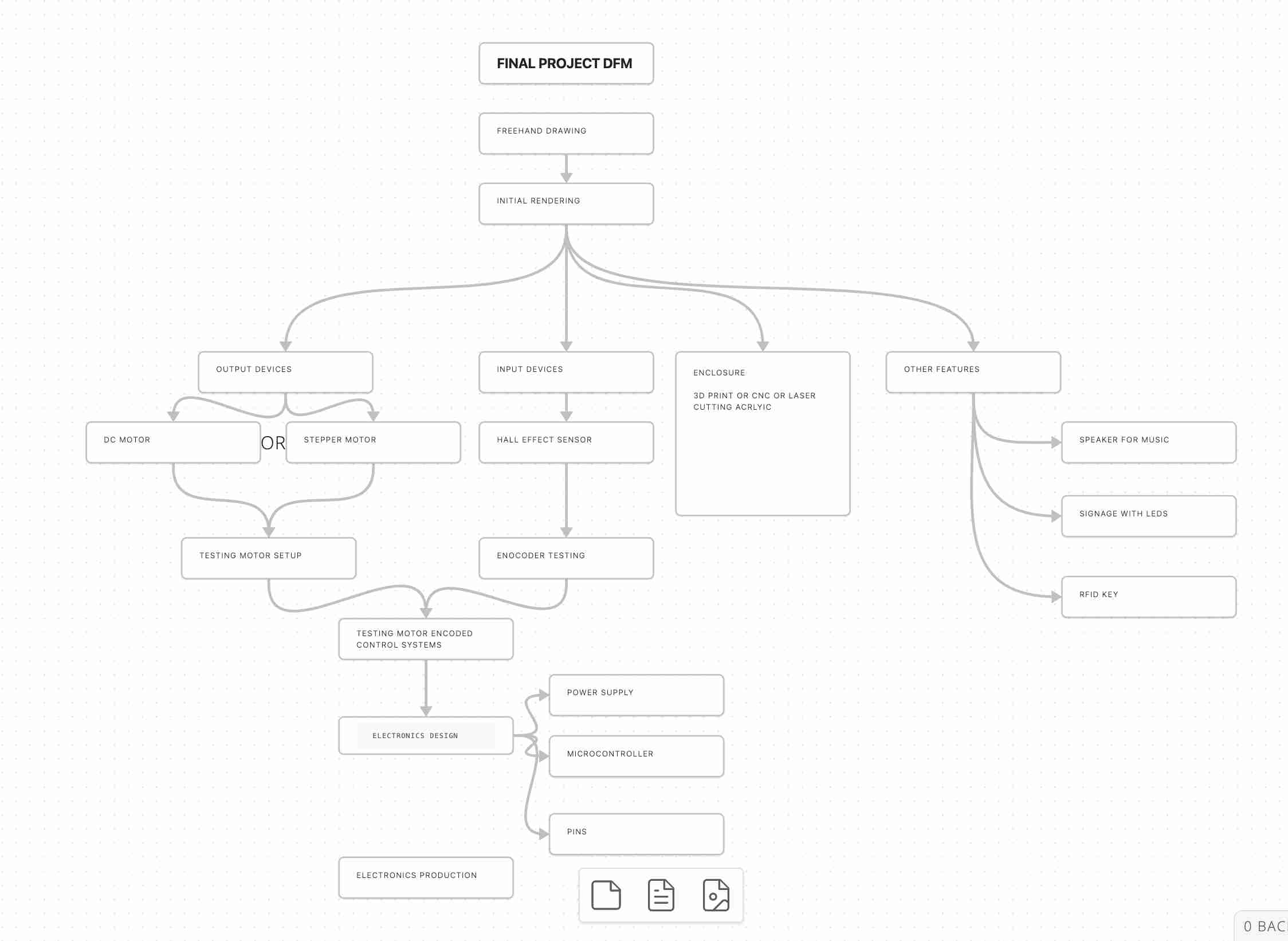
detailed MIND MAP of my final project.
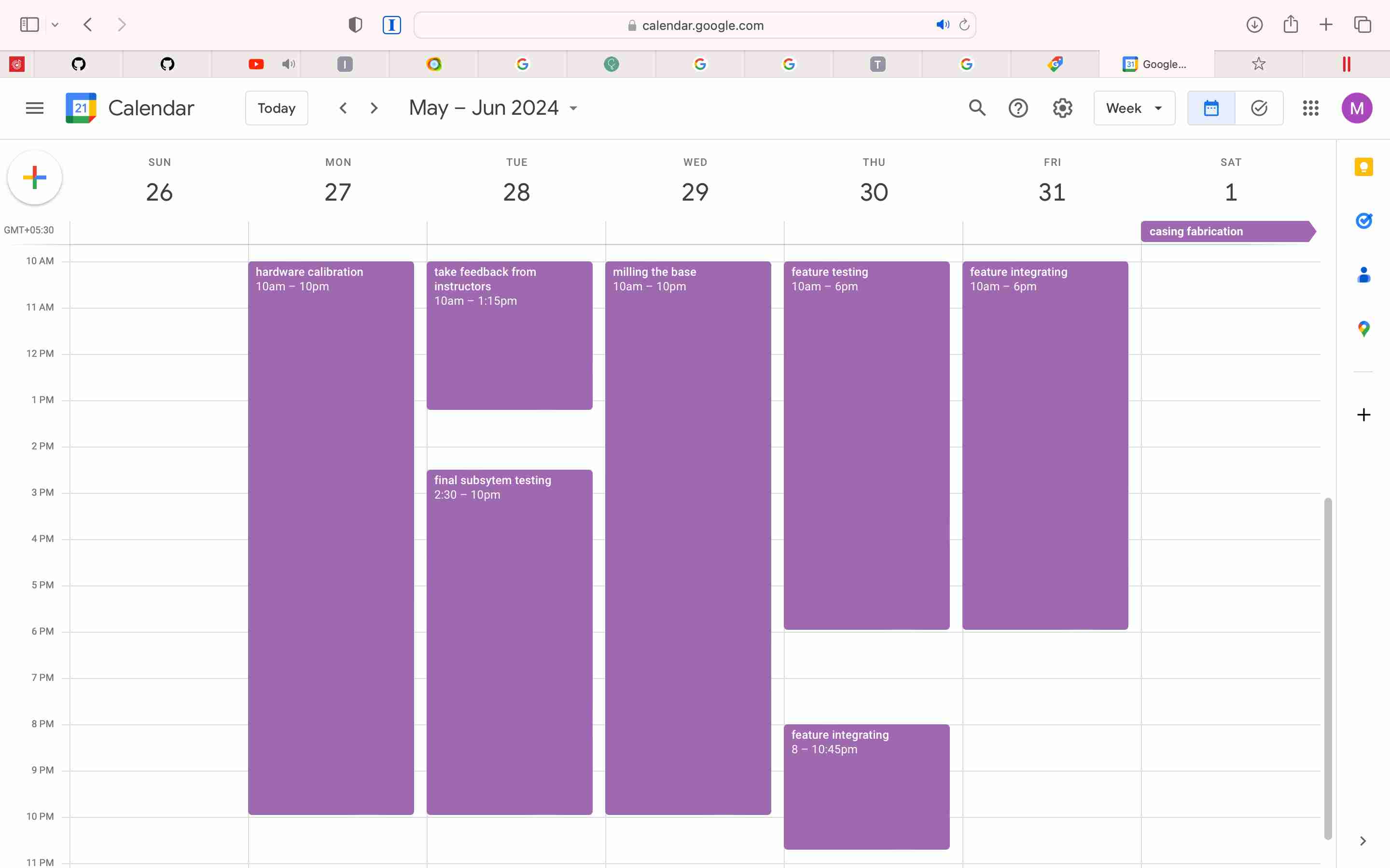
project shedule - google calender
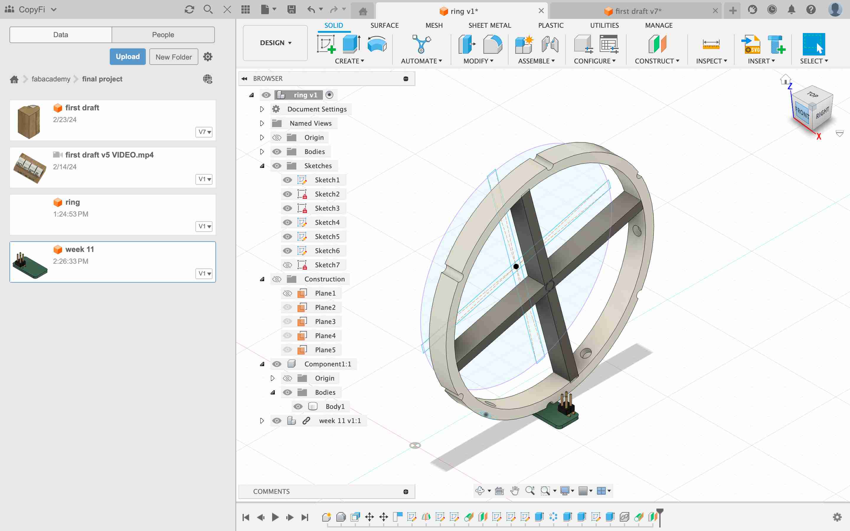
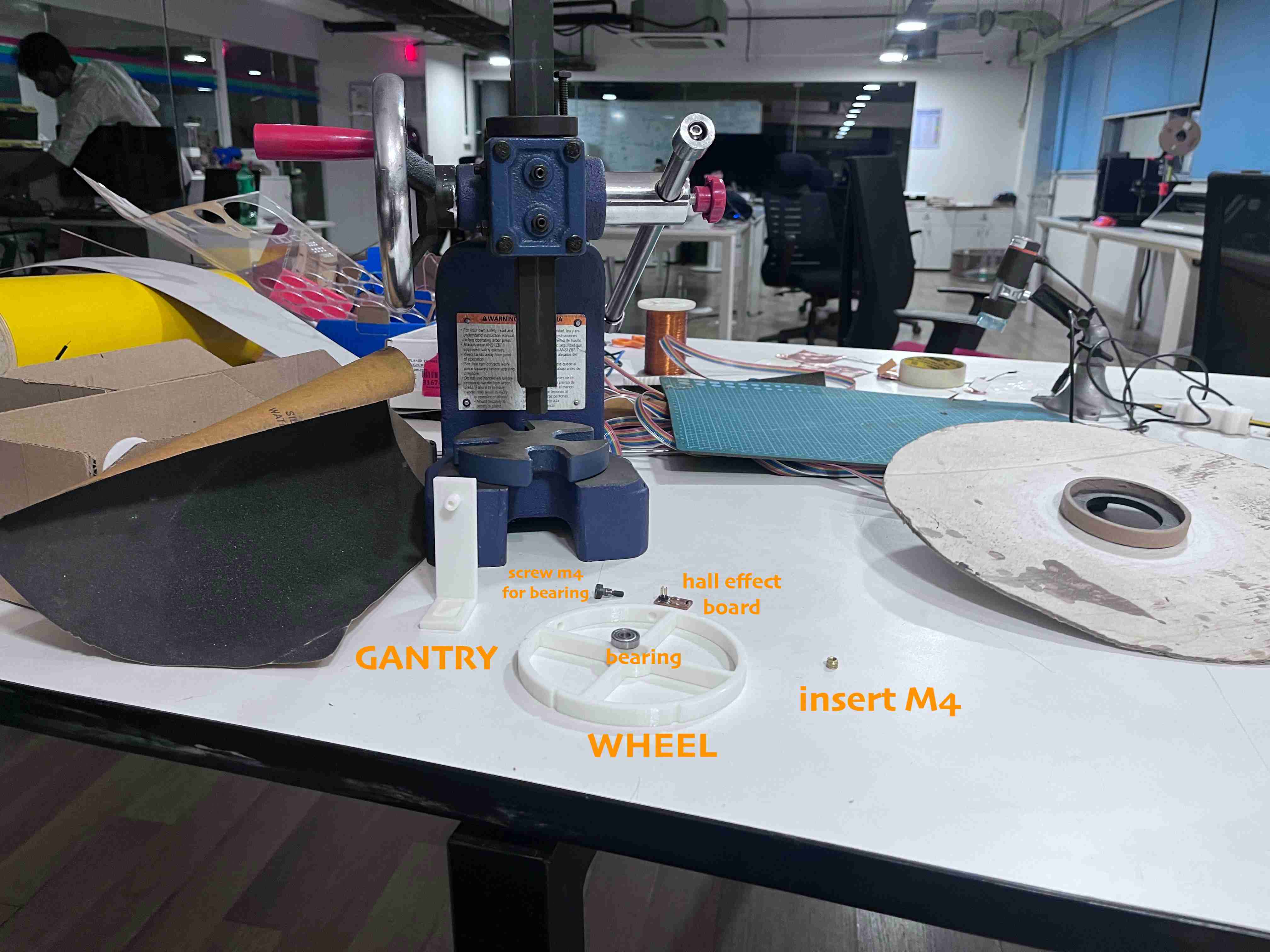
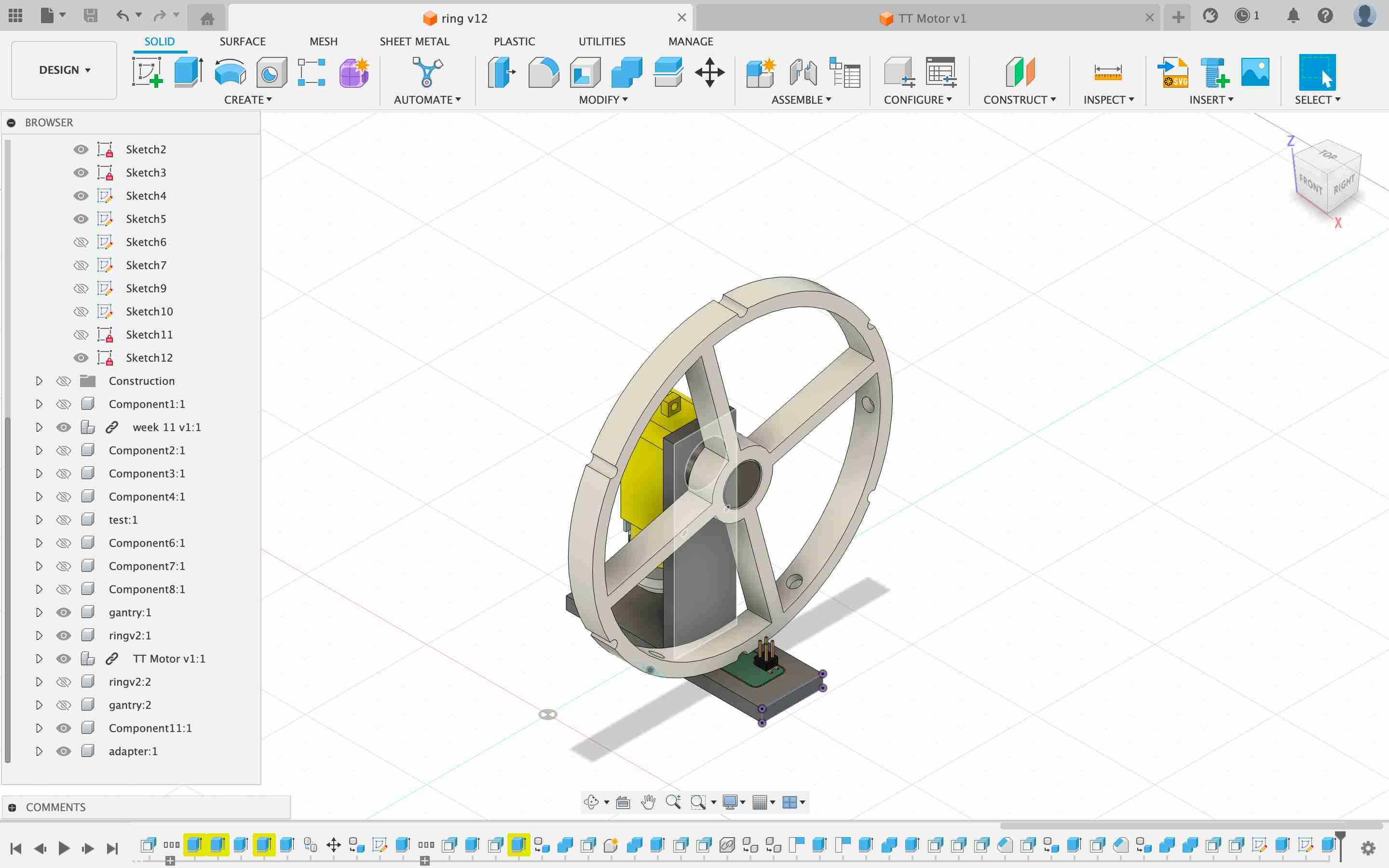
WHEEL DESIGN
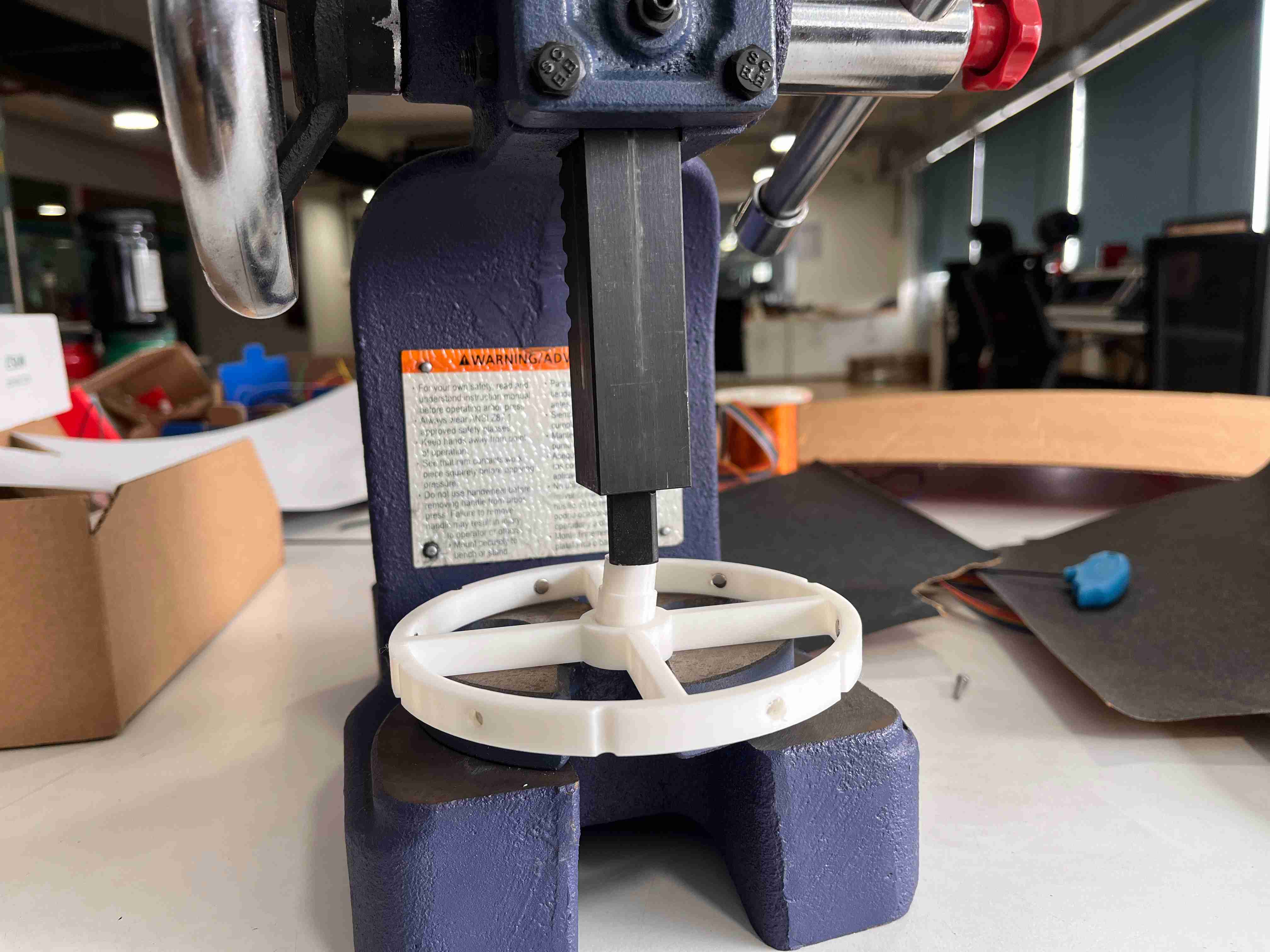
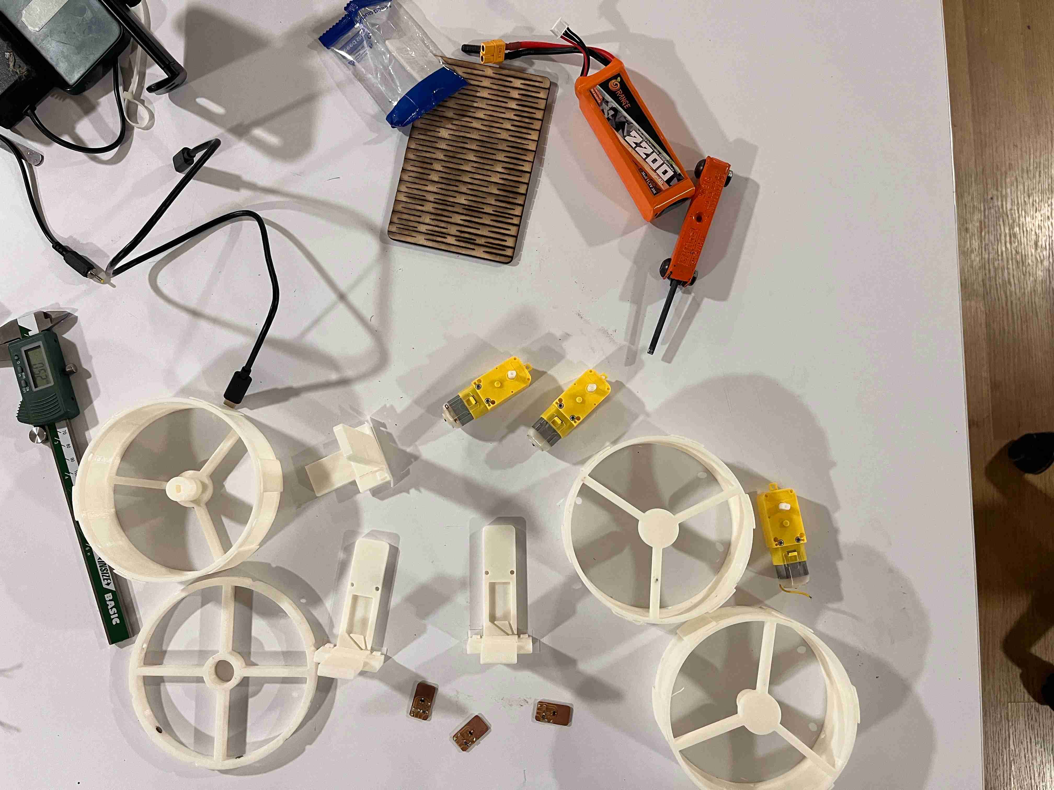
I need to design a single wheel first. However, for testing purposes, I will not print the entire wheel. Instead, I will print a small cross-sectional part of it.
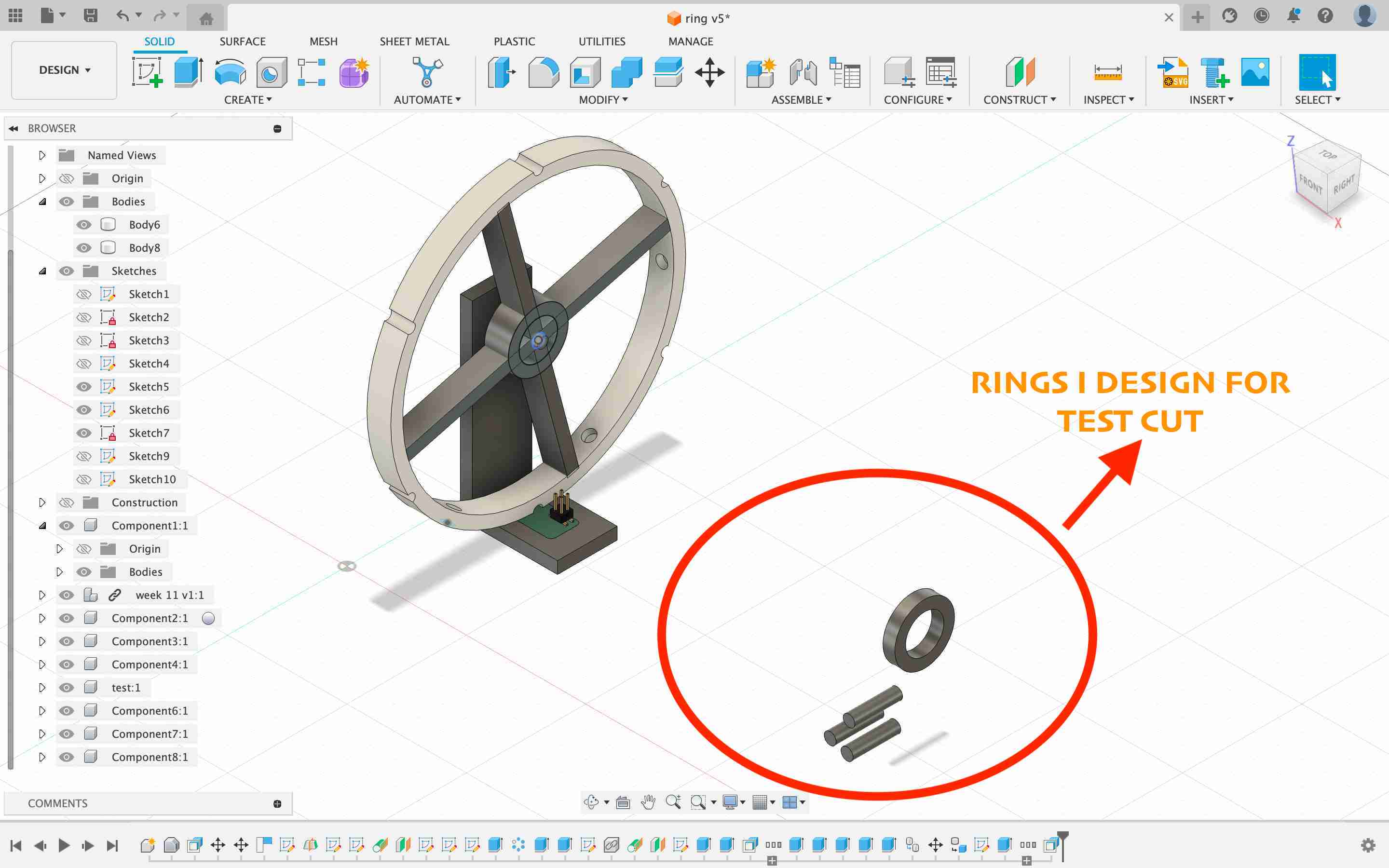
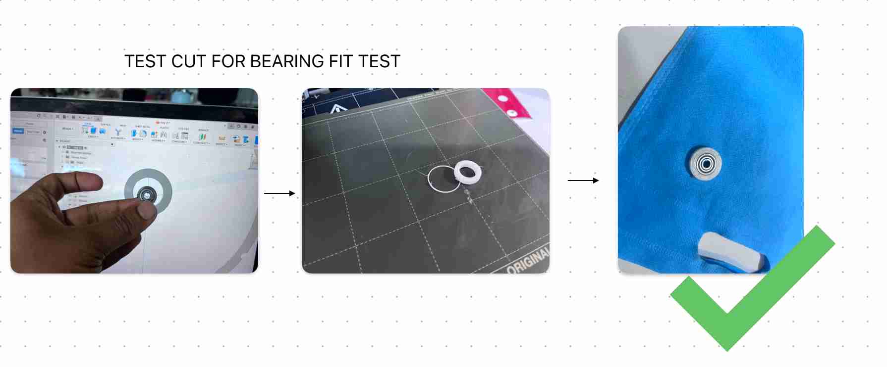
this an area where i need to check whether the bearingfits correct. so instead of printing the whole wheel i just printed a ring with same proportions and checked the fit
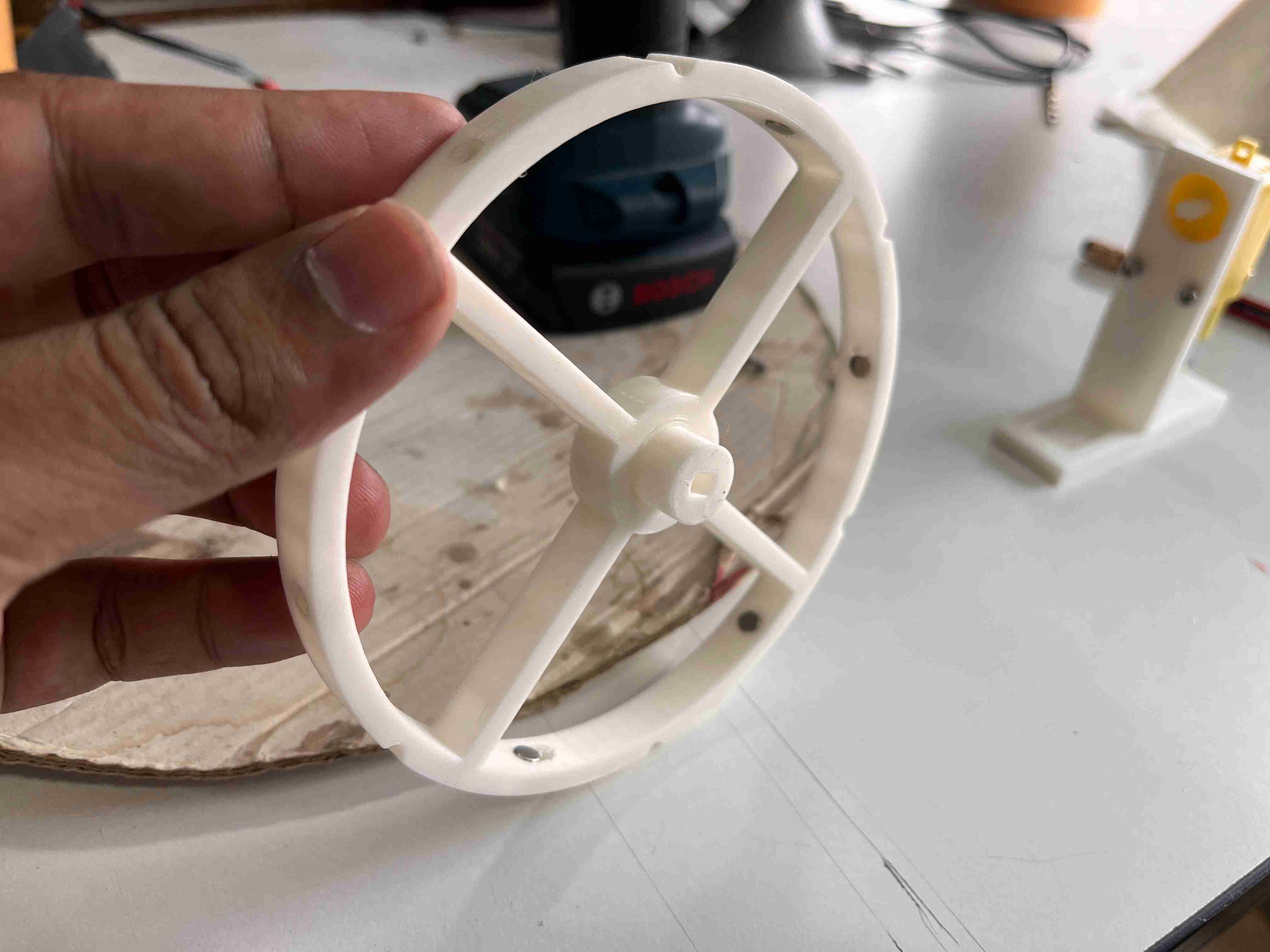
assebling the first version of wheel
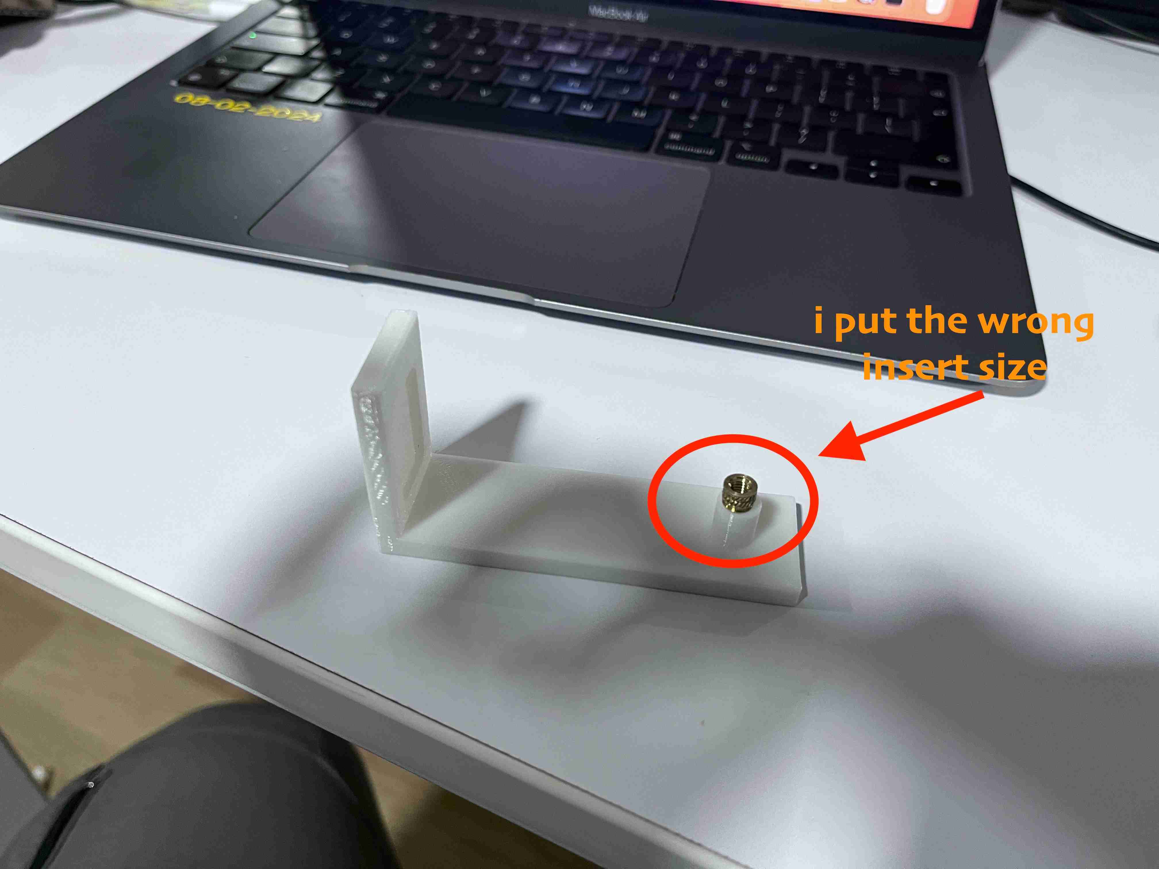
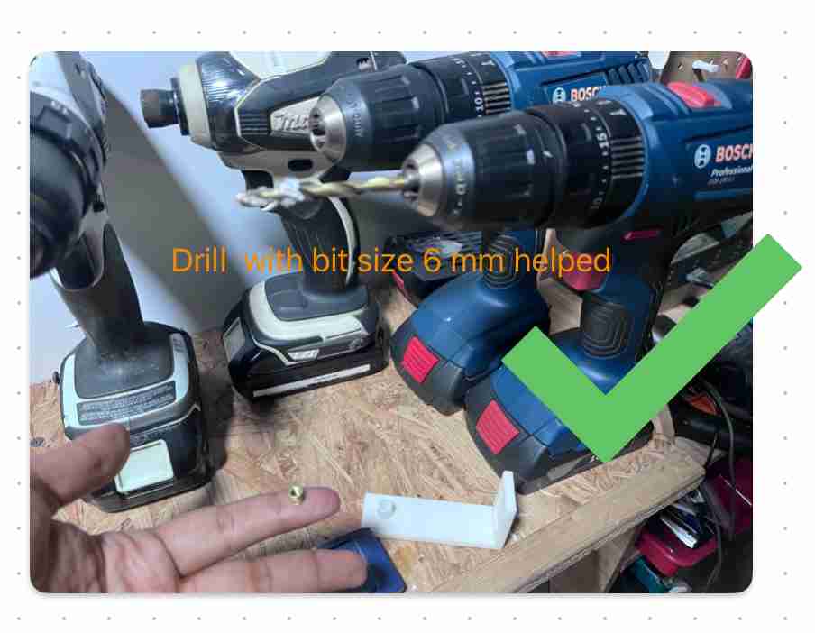
the insert was not fitting properly . so i used a drill widen the hole.
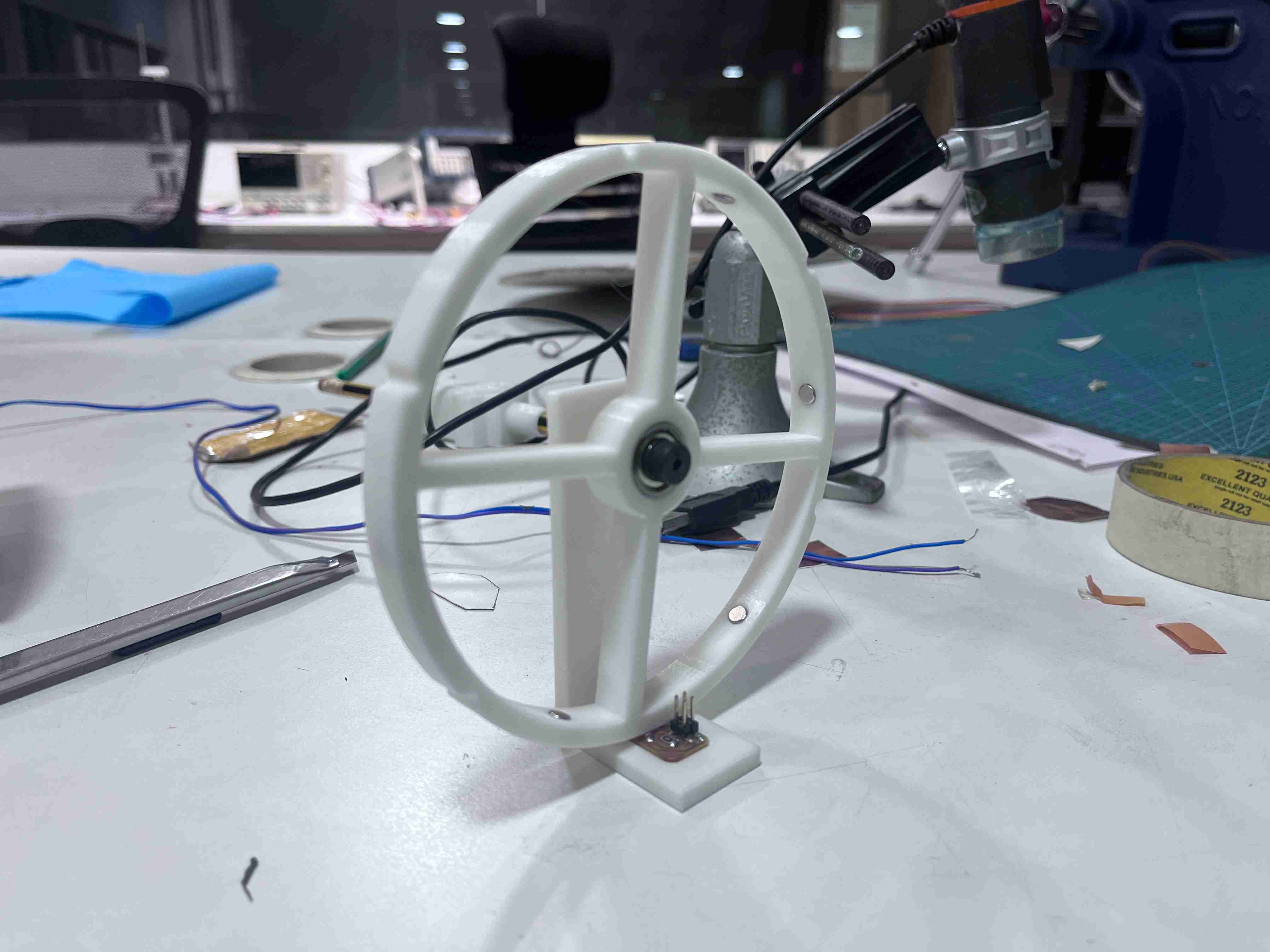
initial version of wheel is ASSEMBLED
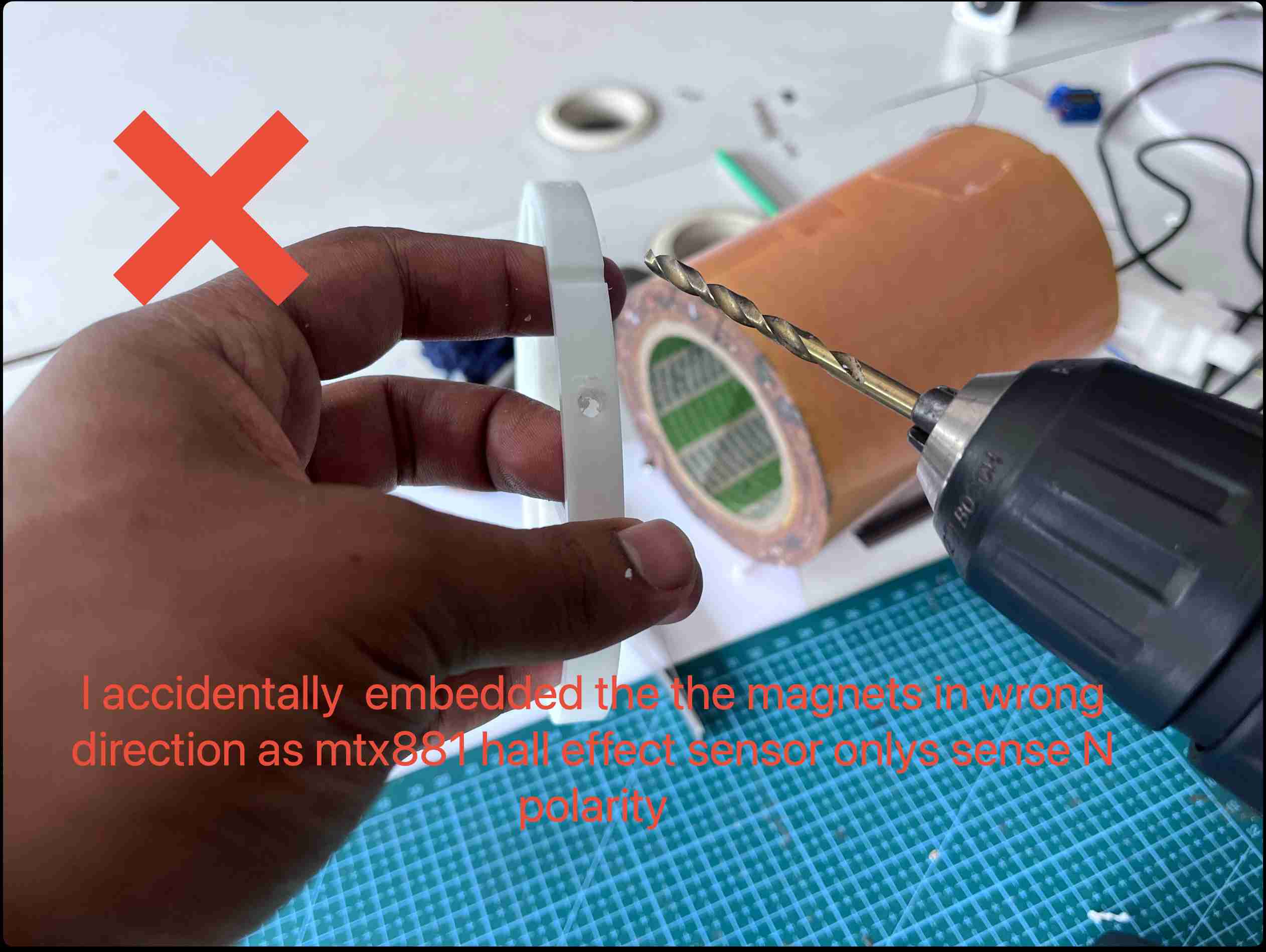
so i have to drill the magnets out and refill it.
in systems design, a fail-fast system is one that immediately reports at its interface any condition that is likely to indicate a failure. Fail-fast systems are usually designed to stop normal operation rather than attempt to continue a possibly flawed process.Wikipedia
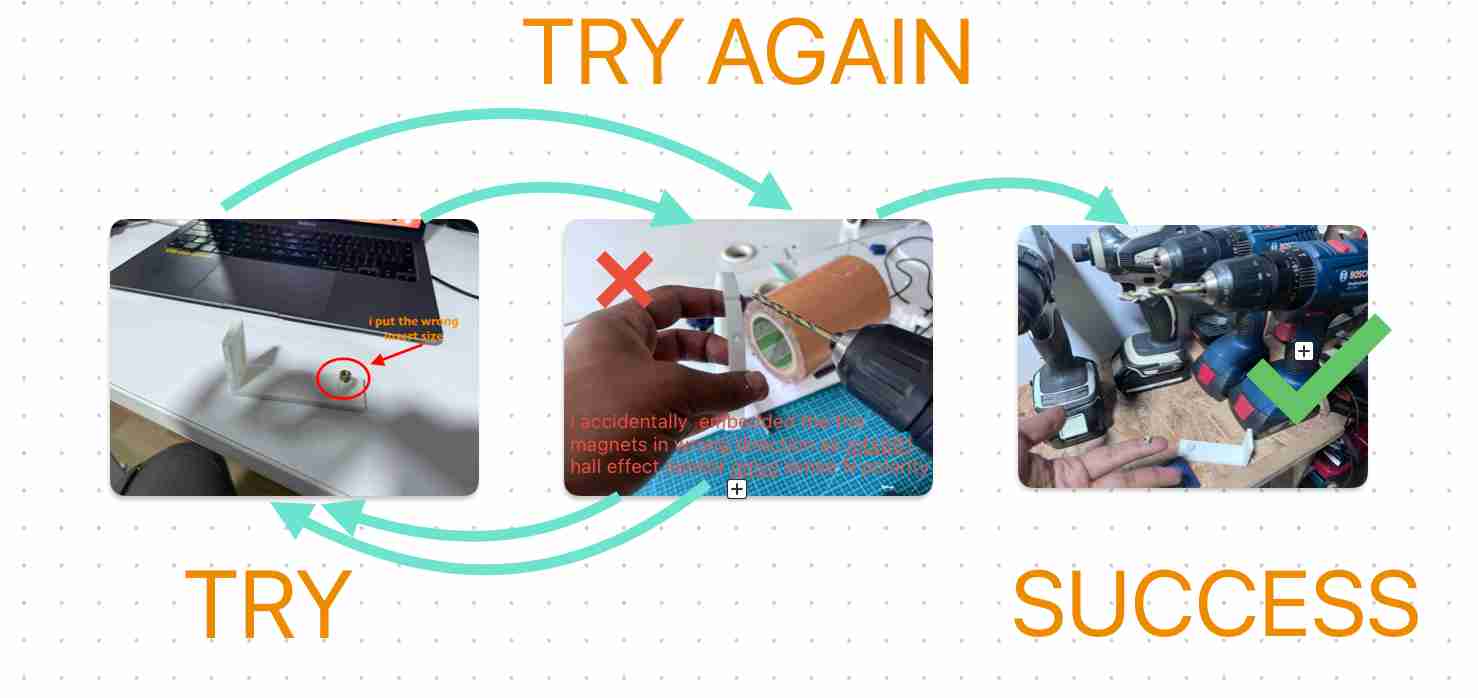
a fail fast situation during working where i failed, iterated and succeeded finally.
programming an encoder
After setting up the first version of the wheel, I am testing how the encoder works. If this test is successful, it means my sensor setup is complete. This will allow the wheel to be referenced easily, enabling it to stop at a specific position and trigger the LED strip, piezo buzzer, etc.
// Define the pin for the hall effect sensor
const int hallEffectPin = 31;
// Variable to store the count of magnet detections
int magnetCount = 0;
// Flag to track whether the sensor was already triggered
bool sensorTriggered = false;
void setup() {
// Initialize serial communication
Serial.begin(9600);
// Set the hall effect sensor pin as input
pinMode(hallEffectPin, INPUT);
}
void loop() {
// Read the state of the hall effect sensor
int sensorState = digitalRead(hallEffectPin);
// If the sensor detects a magnet (LOW state) and it wasn't triggered before
if (sensorState == LOW && !sensorTriggered) {
// Increment the magnet count
magnetCount++;
// Print the current magnet count
Serial.print("Magnet detected! Count: ");
Serial.println(magnetCount);
// Set the sensor triggered flag to true
sensorTriggered = true;
}
// If the sensor is not detecting a magnet (HIGH state)
// reset the sensor triggered flag to false
if (sensorState == HIGH) {
sensorTriggered = false;
}
// // A short delay to prevent rapid counting due to sensor noise
// delay(100);
}
the code
This is done during the input week. You can refer to the WEEK 11 - INPUT DEVICES documentation for more details.
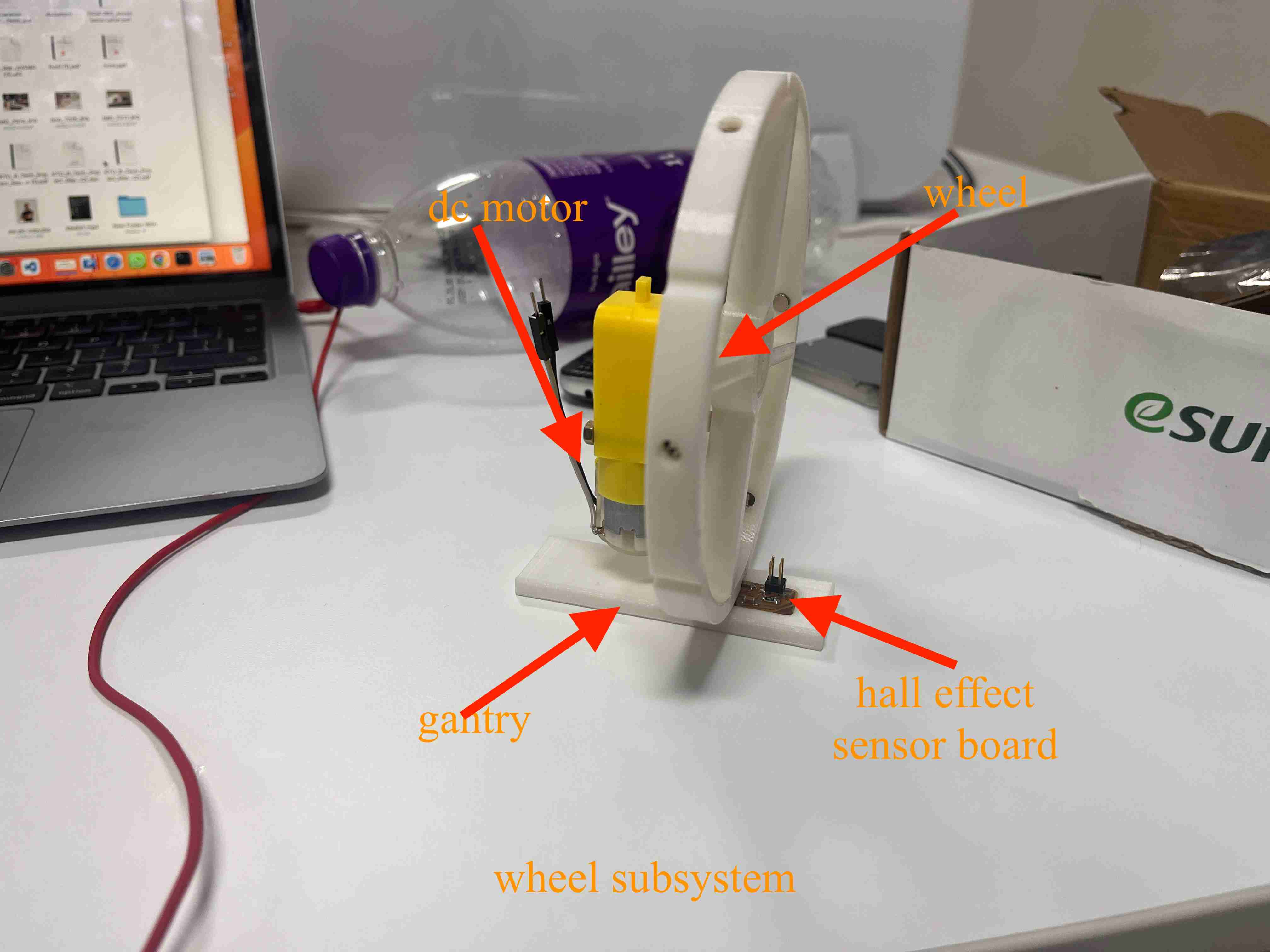
encoder + dc Motor
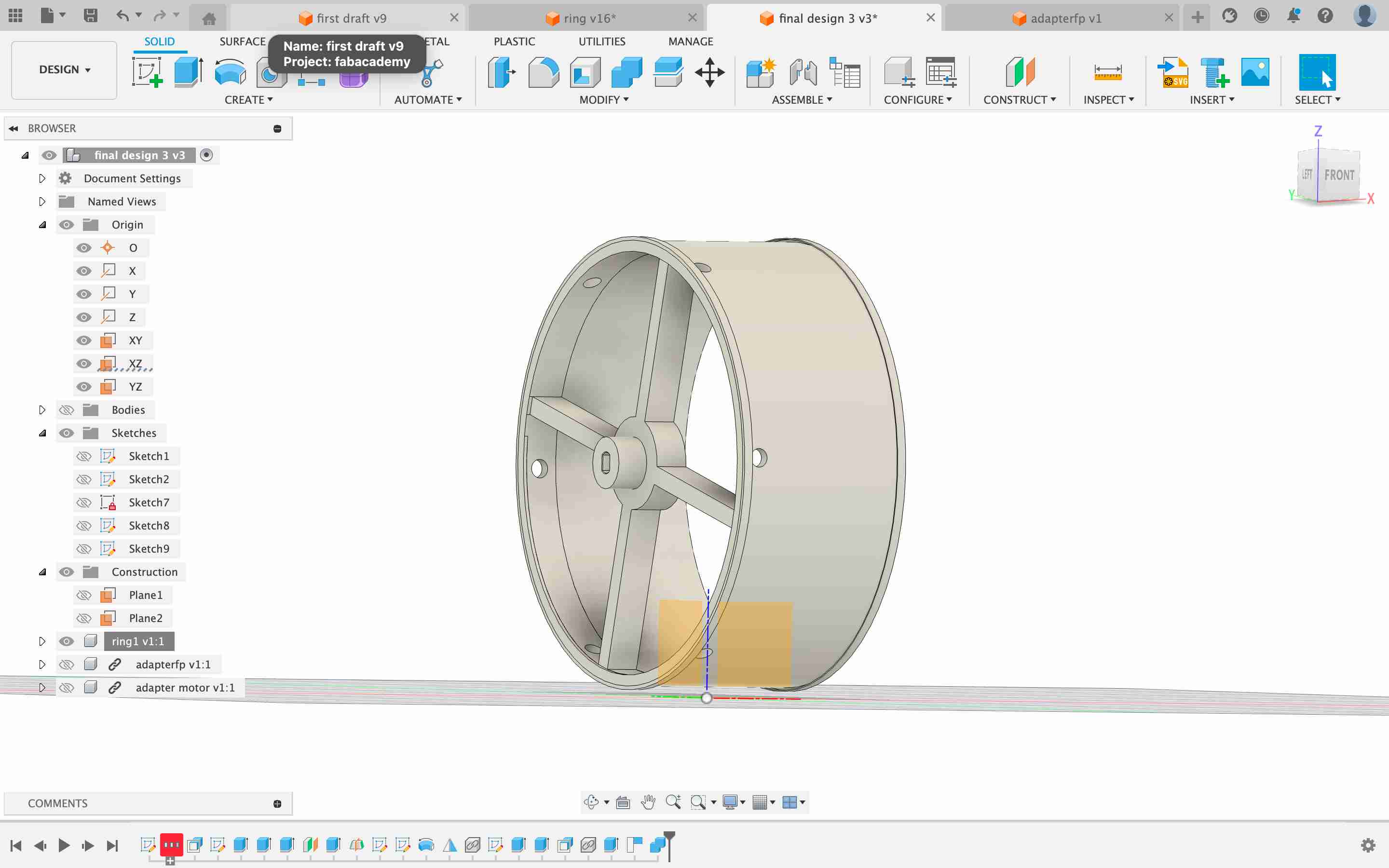
I took a single DC motor and attached it to the wheel setup. I made some changes to the design to accommodate the DC motor. Now, we will turn the motor and get feedback from the wheel through the Hall effect sensor, which will be displayed in the Arduino's serial monitor.
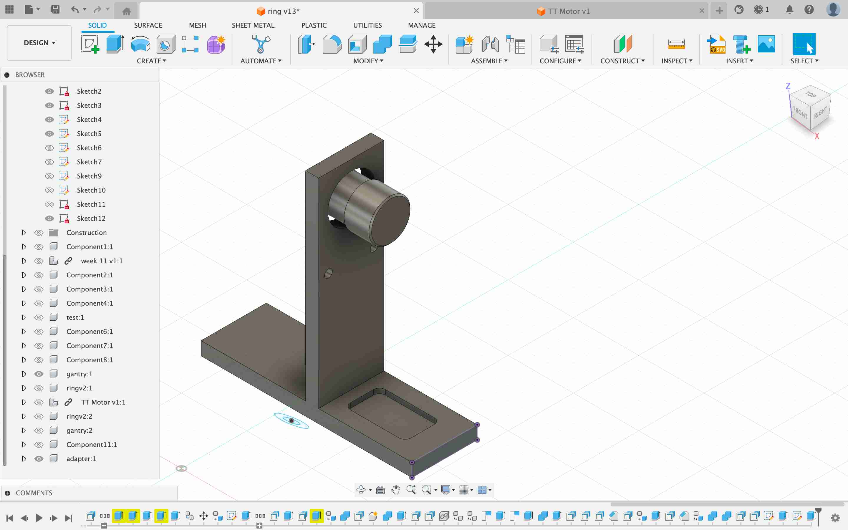
version of wheel setup to accmodate the the motor usign an adapter- reduce wastage of 3dd print

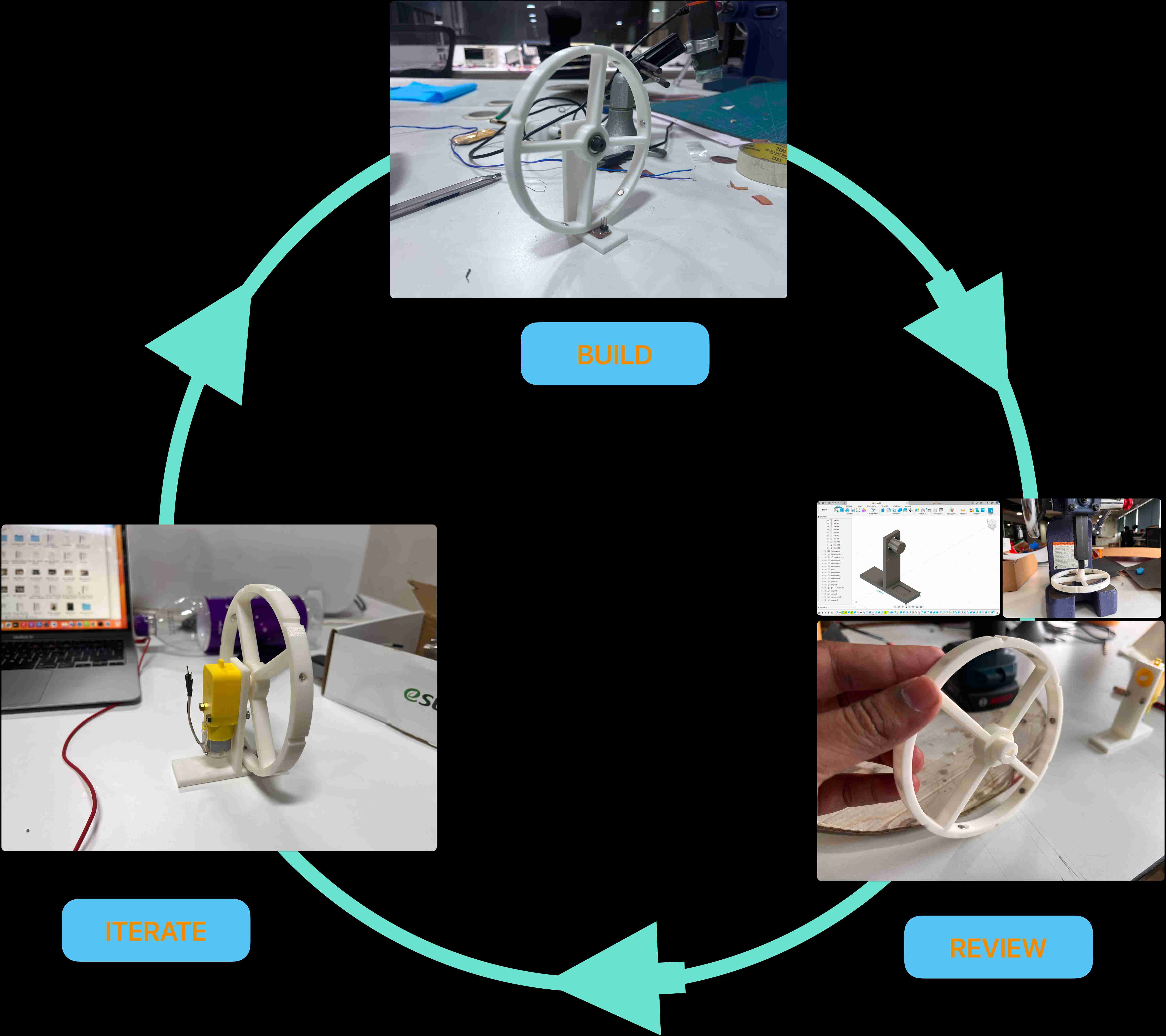
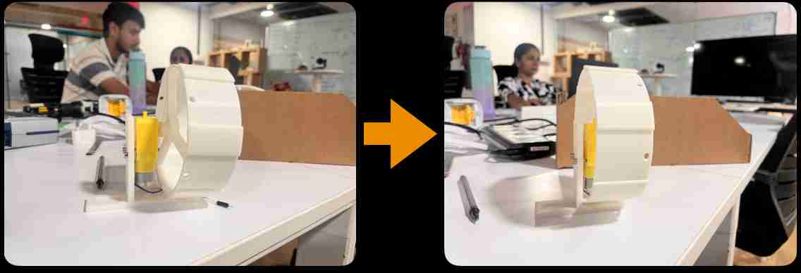
rapid prototyping process
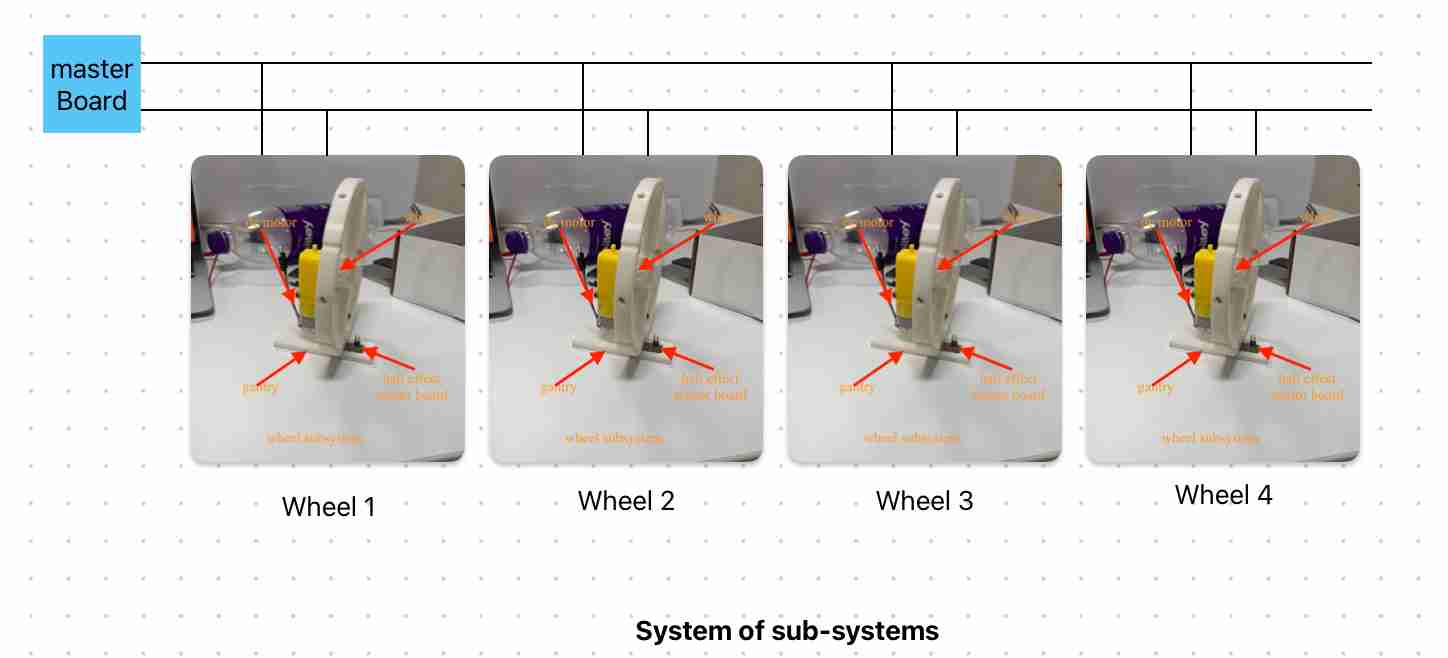
i have this gantry wheel setup to test my dc motor + hall effect sensor encoder which is the main subsystem of my project. if this work i can control my wheel to any position i believe my PROJECT is 50% done. so what i have done is, i made this minimum wheel in the iWEEK 11 - INPUT DEVICES week to test the setup.
basically if i have done one wheel my whole project is copying it four times and integrating it with a master board.
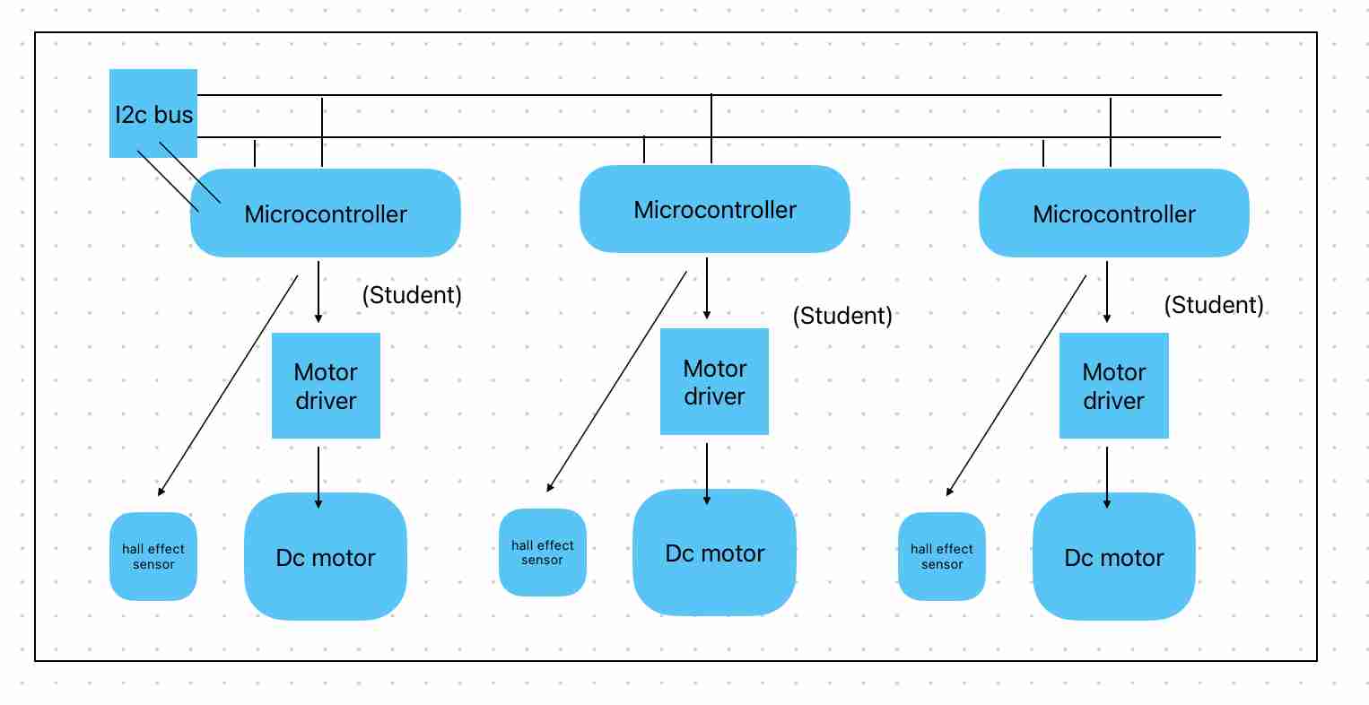
detailed flow cahrt of my elctronic setup
i
i am testing the motor wheel setup using board made in WEEK 13 - NETWORKING AND COMMUNICATIONS
// Define the pin for the MOSFET gate
const int motorPin = 4;
void setup() {
// Set the motor pin as an output
pinMode(motorPin, OUTPUT);
}
void loop() {
// Ramp up the speed from 0 to 255 (full speed) smoothly
for (int speed = 0; speed <= 255; speed++) {
analogWrite(motorPin, speed);
delay(10); // Adjust the delay for smoother or faster ramp-up
}
delay(1000); // Run at full speed for 1 second
// Ramp down the speed from 255 to 0 smoothly
for (int speed = 255; speed >= 0; speed--) {
analogWrite(motorPin, speed);
delay(10); // Adjust the delay for smoother or faster ramp-down
}
delay(1000); // Stay off for 1 second
}
Testing with ramping down the motor was a bit difficult. It took some time to finalize the code for ramping the motor up and down.
Issue on 24/05/2024: Debugging the motor not working with the following code:
// Define the pin for the hall effect sensor
const int hallEffectPin = 2;
// Define the pin for the motor
const int motorPin = 4;
// Variable to store the count of magnet detections
int magnetCount = 0;
// Flag to track whether the sensor was already triggered
bool sensorTriggered = false;
// Flag to indicate ramp-down process
bool rampingDown = false;
void setup() {
// Initialize serial communication
Serial.begin(9600);
// Set the hall effect sensor pin as input
pinMode(hallEffectPin, INPUT);
// Set the motor pin as an output and default it to high
pinMode(motorPin, OUTPUT);
digitalWrite(motorPin, HIGH);
}
void loop() {
// Read the state of the hall effect sensor
int sensorState = digitalRead(hallEffectPin);
// If the sensor detects a magnet (LOW state) and it wasn't triggered before
if (sensorState == LOW && !sensorTriggered) {
// Increment the magnet count
magnetCount++;
// Print the current magnet count
Serial.print("Magnet detected! Count: ");
Serial.println(magnetCount);
// Set the sensor triggered flag to true
sensorTriggered = true;
// Check if the magnet count is the trigger count
if (magnetCount == 1) {
// Start the ramp-down process
rampingDown = true;
}
}
// If the sensor is not detecting a magnet (HIGH state)
// reset the sensor triggered flag to false
if (sensorState == HIGH) {
sensorTriggered = false;
}
// Check if the motor is ramping down
if (rampingDown) {
// Ramp down the motor
rampDownMotor();
}
// A short delay to prevent rapid counting due to sensor noise
delay(10);
}
// Function to ramp down the motor smoothly
void rampDownMotor() {
static int motorSpeed = 255; // Initial motor speed
motorSpeed -= 5; // Decrease motor speed gradually
analogWrite(motorPin, max(0, motorSpeed)); // Update motor speed
// Check if motor speed has reached 0
if (motorSpeed <= 0) {
// Stop the motor
digitalWrite(motorPin, LOW);
Serial.println("Motor ramped down and stopped.");
// Reset flags and variables for next cycle
rampingDown = false;
magnetCount = 0; // Reset magnet count
}
}
//issue
Motor ramped down and stopped.
Magnet detected! Count: 1
Motor ramped down and stopped.
Magnet detected! Count: 1
Motor ramped down and stopped.
Magnet detected! Count: 1
Motor ramped down and stopped.
the magnet count is reset after each ramp down . so the motor is not running visually.
motor ramping down and up - debugged - still ahve some issues
piezo buzzer
I planned to incorporate a piezo buzzer to create audio animations that go with the motor movement. Here is my test of the piezo buzzer creating different music
#define NOTE_B0 31
#define NOTE_C1 33
#define NOTE_CS1 35
#define NOTE_D1 37
#define NOTE_DS1 39
#define NOTE_E1 41
#define NOTE_F1 44
#define NOTE_FS1 46
#define NOTE_G1 49
#define NOTE_GS1 52
#define NOTE_A1 55
#define NOTE_AS1 58
#define NOTE_B1 62
#define NOTE_C2 65
#define NOTE_CS2 69
#define NOTE_D2 73
#define NOTE_DS2 78
#define NOTE_E2 82
#define NOTE_F2 87
#define NOTE_FS2 93
#define NOTE_G2 98
#define NOTE_GS2 104
#define NOTE_A2 110
#define NOTE_AS2 117
#define NOTE_B2 123
#define NOTE_C3 131
#define NOTE_CS3 139
#define NOTE_D3 147
#define NOTE_DS3 156
#define NOTE_E3 165
#define NOTE_F3 175
#define NOTE_FS3 185
#define NOTE_G3 196
#define NOTE_GS3 208
#define NOTE_A3 220
#define NOTE_AS3 233
#define NOTE_B3 247
#define NOTE_C4 262
#define NOTE_CS4 277
#define NOTE_D4 294
#define NOTE_DS4 311
#define NOTE_E4 330
#define NOTE_F4 349
#define NOTE_FS4 370
#define NOTE_G4 392
#define NOTE_GS4 415
#define NOTE_A4 440
#define NOTE_AS4 466
#define NOTE_B4 494
#define NOTE_C5 523
#define NOTE_CS5 554
#define NOTE_D5 587
#define NOTE_DS5 622
#define NOTE_E5 659
#define NOTE_F5 698
#define NOTE_FS5 740
#define NOTE_G5 784
#define NOTE_GS5 831
#define NOTE_A5 880
#define NOTE_AS5 932
#define NOTE_B5 988
#define NOTE_C6 1047
#define NOTE_CS6 1109
#define NOTE_D6 1175
#define NOTE_DS6 1245
#define NOTE_E6 1319
#define NOTE_F6 1397
#define NOTE_FS6 1480
#define NOTE_G6 1568
#define NOTE_GS6 1661
#define NOTE_A6 1760
#define NOTE_AS6 1865
#define NOTE_B6 1976
#define NOTE_C7 2093
#define NOTE_CS7 2217
#define NOTE_D7 2349
#define NOTE_DS7 2489
#define NOTE_E7 2637
#define NOTE_F7 2794
#define NOTE_FS7 2960
#define NOTE_G7 3136
#define NOTE_GS7 3322
#define NOTE_A7 3520
#define NOTE_AS7 3729
#define NOTE_B7 3951
#define NOTE_C8 4186
#define NOTE_CS8 4435
#define NOTE_D8 4699
#define NOTE_DS8 4978
pitches.h
#include "pitches.h"
const int buzzerPin = 9;
// Notes of "Für Elise" melody and their durations
int melody[] = {
NOTE_E5, NOTE_DS5, NOTE_E5, NOTE_DS5, NOTE_E5, NOTE_B4, NOTE_D5, NOTE_C5,
NOTE_A4, 0, NOTE_C4, NOTE_E4, NOTE_A4, NOTE_B4, 0, NOTE_E4, NOTE_GS4, NOTE_B4,
NOTE_C5, 0, NOTE_E4, NOTE_E5, NOTE_DS5, NOTE_E5, NOTE_DS5, NOTE_E5, NOTE_B4,
NOTE_D5, NOTE_C5, NOTE_A4, 0, NOTE_C4, NOTE_E4, NOTE_A4, NOTE_B4, 0, NOTE_E4,
NOTE_C5, NOTE_B4, NOTE_A4
};
int noteDurations[] = {
8, 8, 8, 8, 8, 8, 8, 8,
4, 8, 8, 8, 8, 4, 8, 8,
8, 8, 8, 4, 8, 8, 8, 8,
8, 8, 8, 8, 8, 4, 8, 8,
8, 8, 4, 8, 8, 8, 4
};
void setup() {
// No setup code needed for this example
}
void loop() {
for (int thisNote = 0; thisNote < sizeof(melody) / sizeof(int); thisNote++) {
int noteDuration = 1000 / noteDurations[thisNote];
tone(buzzerPin, melody[thisNote], noteDuration);
int pauseBetweenNotes = noteDuration * 1.30;
delay(pauseBetweenNotes);
noTone(buzzerPin);
}
delay(2000); // Wait for 2 seconds before repeating the melody
}
the code
testing piezo buzzer
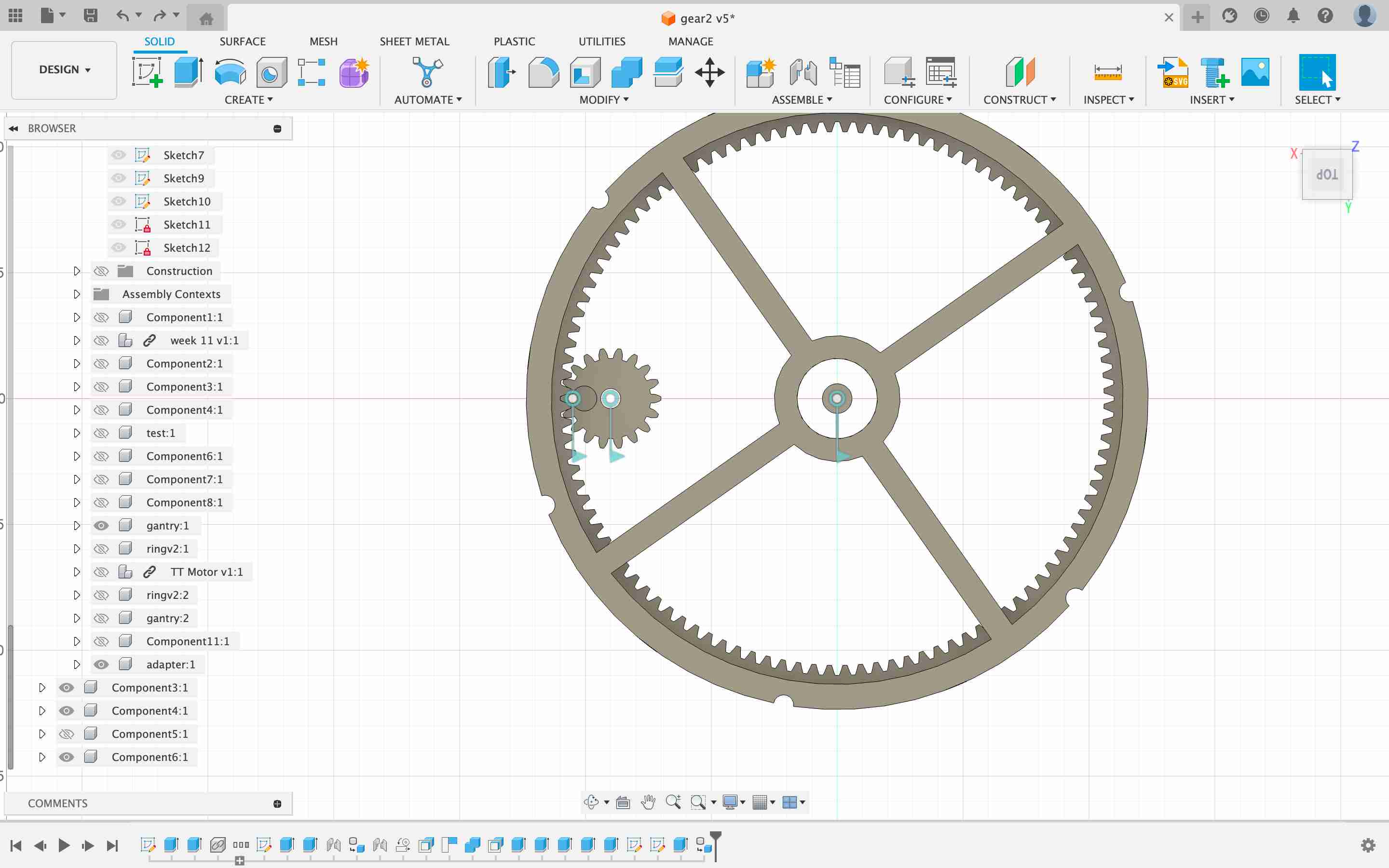
problem with gear reduction
To reduce the number of magnets needed for the four wheels, I introduced gears where a single magnet is attached to the smaller gear. The gears have a 1:6 ratio, meaning for every full rotation of the wheel, the magnet triggers six times.
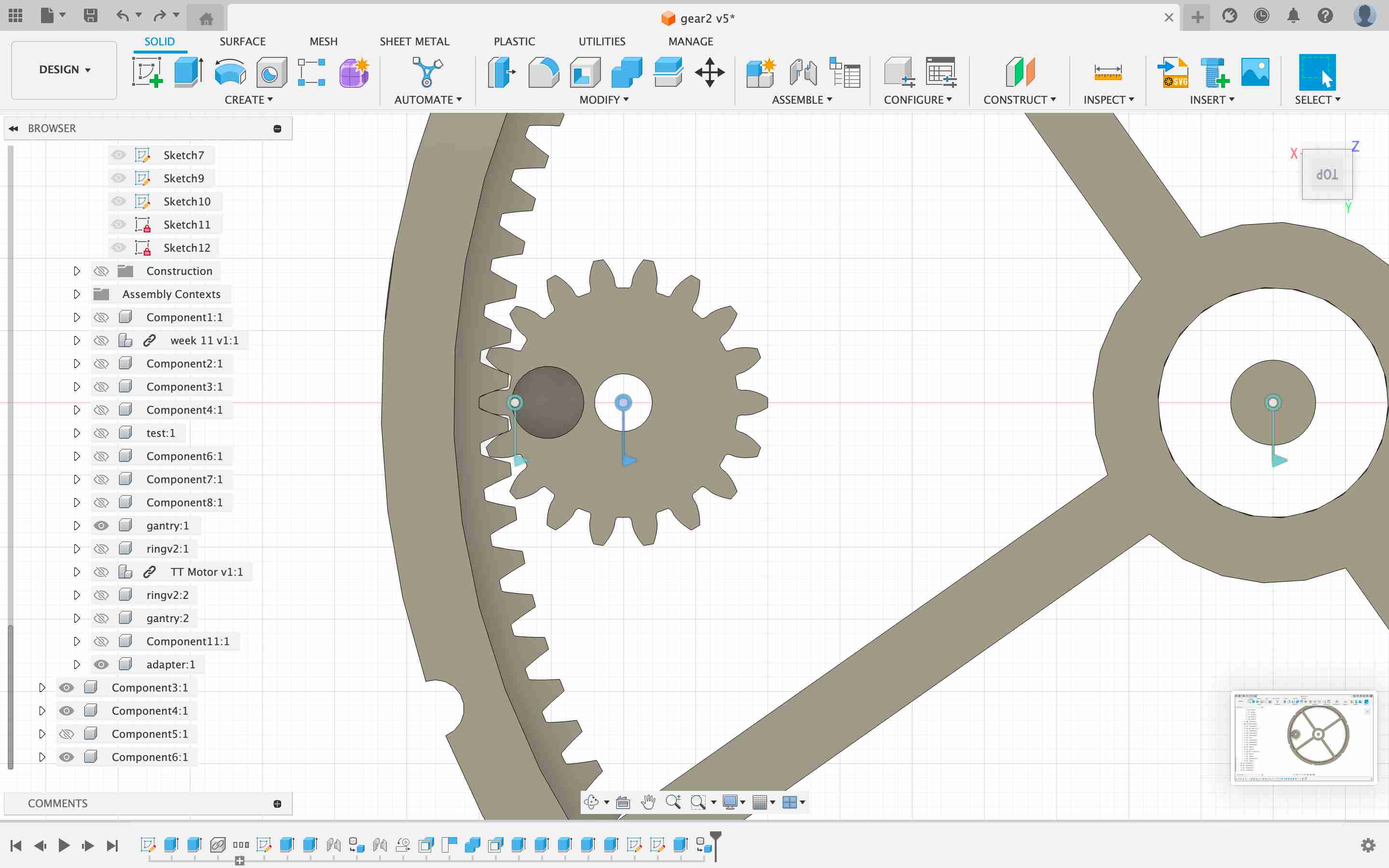
I found that this approach is complicating things, and with time running out, I need to focus on completing the remaining important tasks.
progress wheel
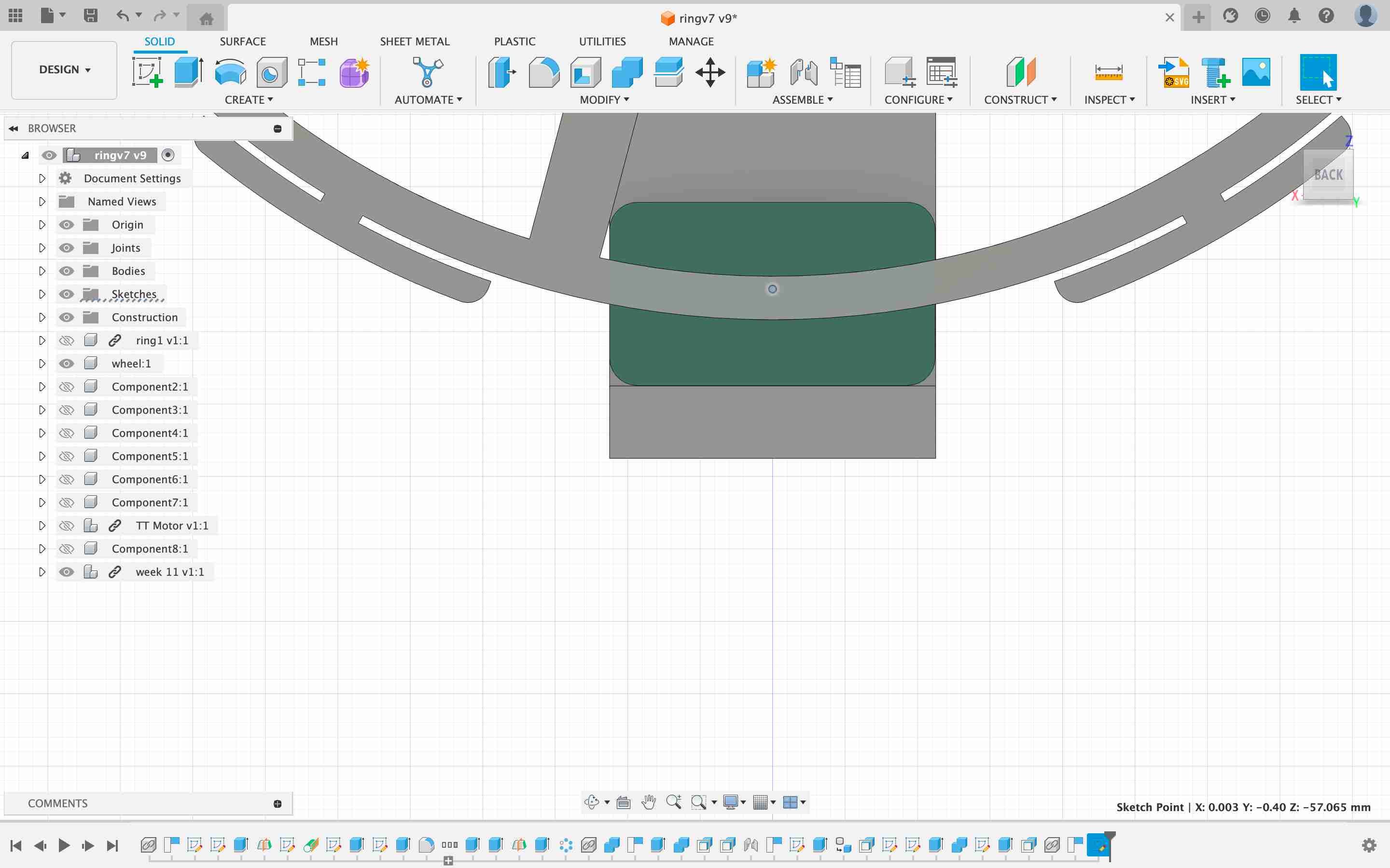
After printing the complete layout, I realised I could make the design more compact and modular by inverting the wheel. This was a moment of insight
after making the design of the wheel better by just flipping it
electronics breakout
Then I had the idea of integrating a Hall effect board with the motor MOSFET. This would reduce the total number of wires from one wheel module to four. I felt this approach would be more streamlined and proceeded with it.
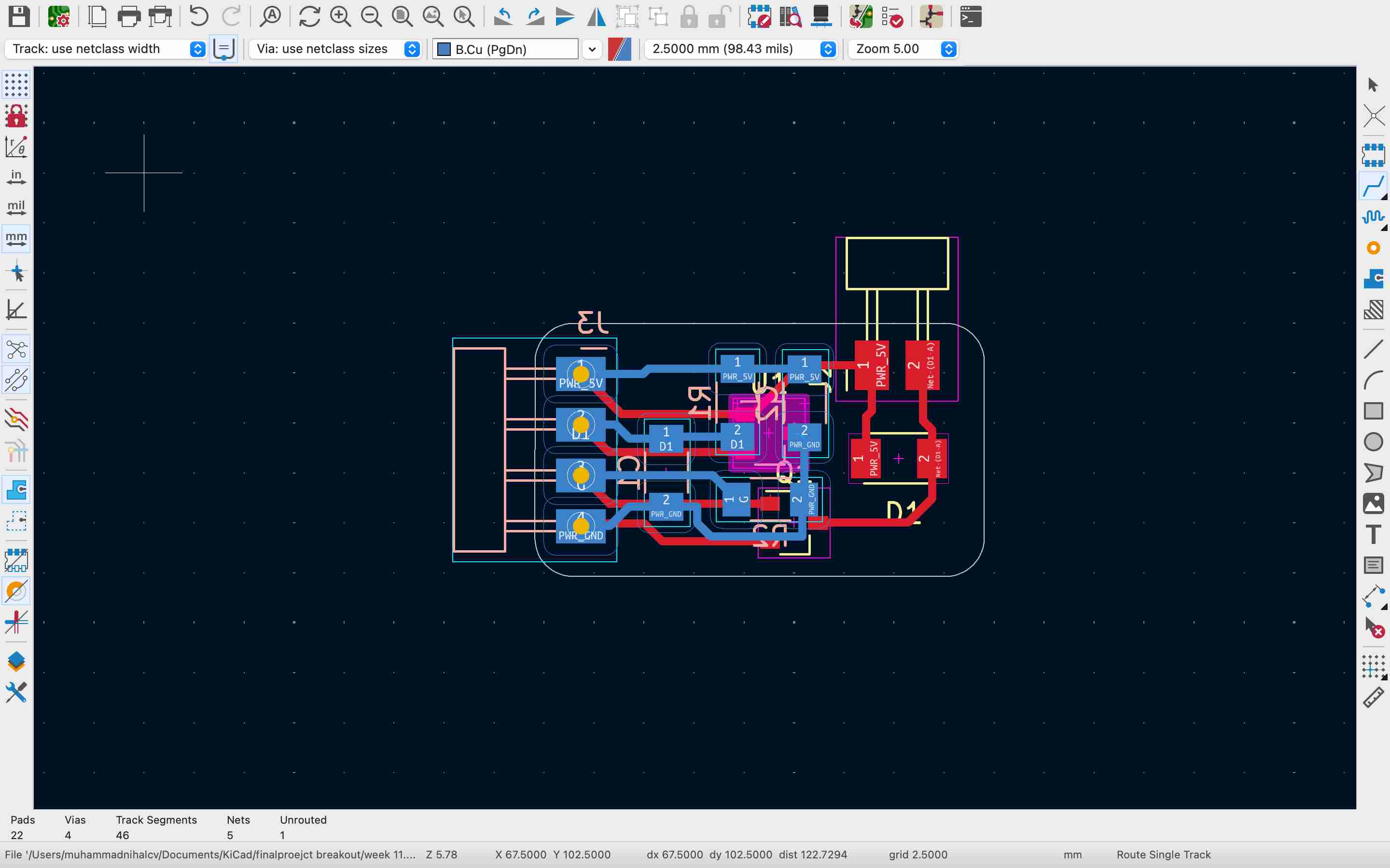
I ran into a problem where the board wasn't functioning correctly. When powering both the Hall effect sensors and motors, the Hall effect sensor gave false triggers and the motor behaved erratically. This attempt ultimately failed.
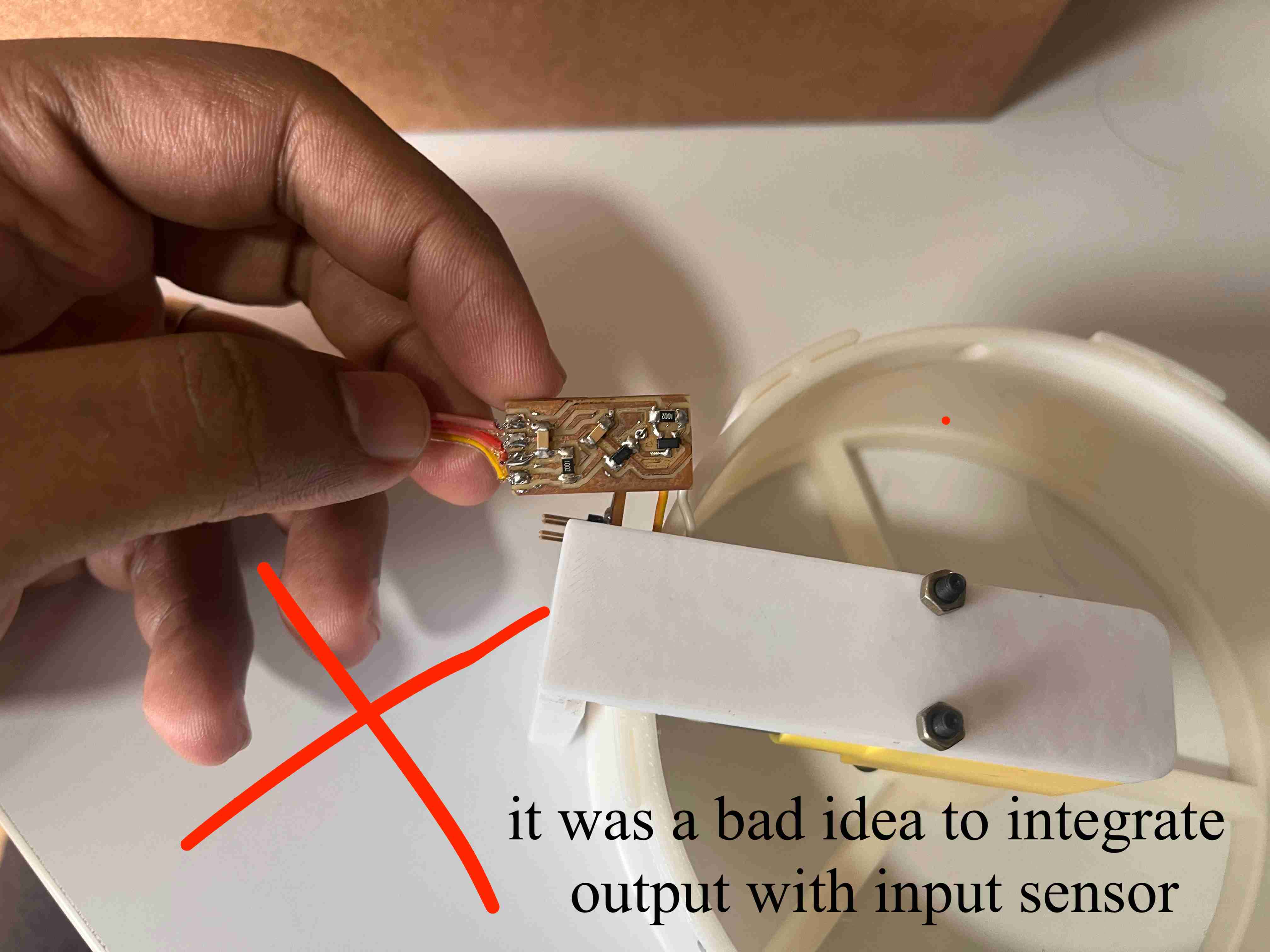
failed move
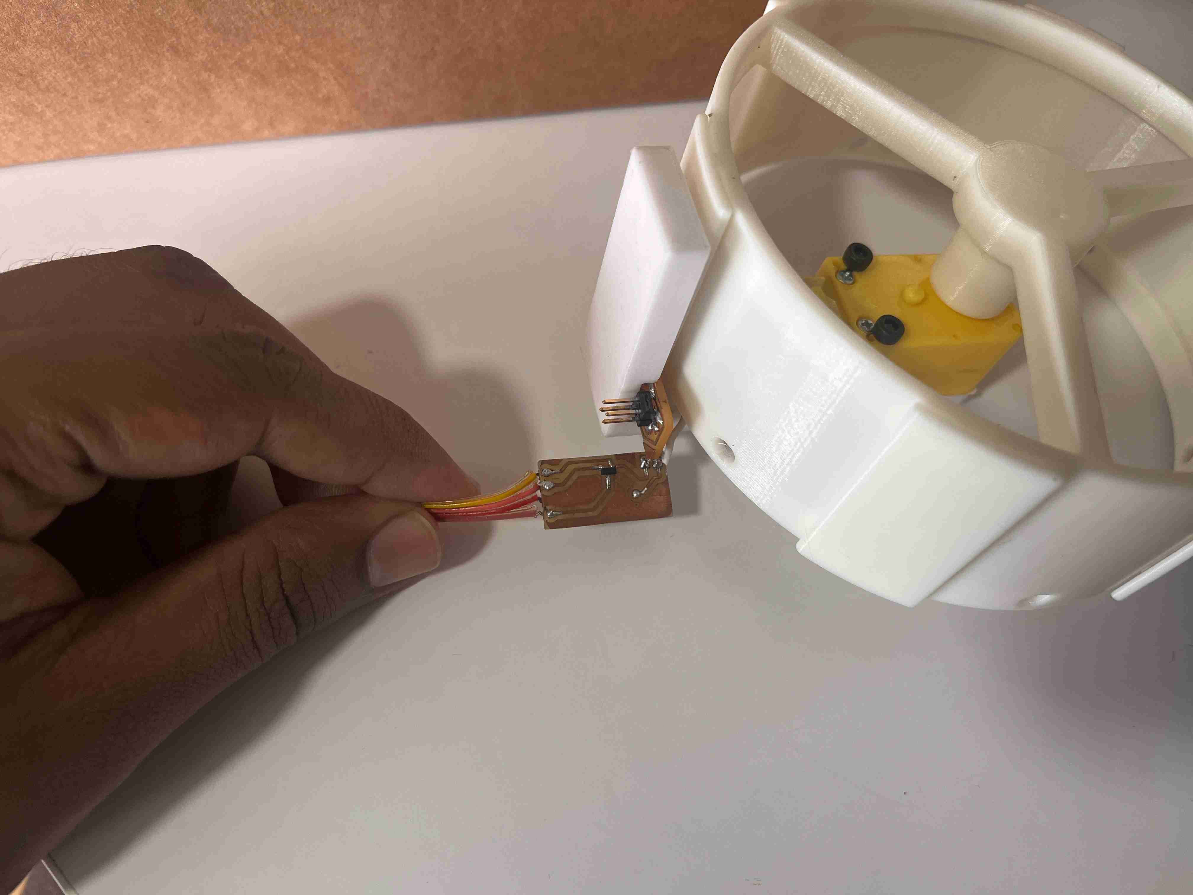
I then opted for the WEEK 11 - INPUT DEVICES using separate Hall effect sensors and made modifications to ensure they were properly attached to the new gantry setup.
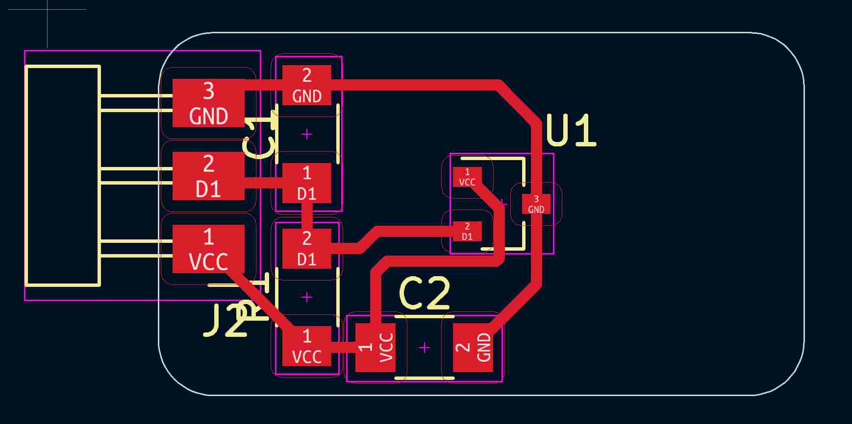
final routing of the hall effect board - final project
routing the base
To ensure a strong base, I routed the base from 18 mm plywood after designing it in Fusion 360, including pockets for all four gantries and wheel accommodations. The routing was done on a Zund machine, and it turned out nicely.
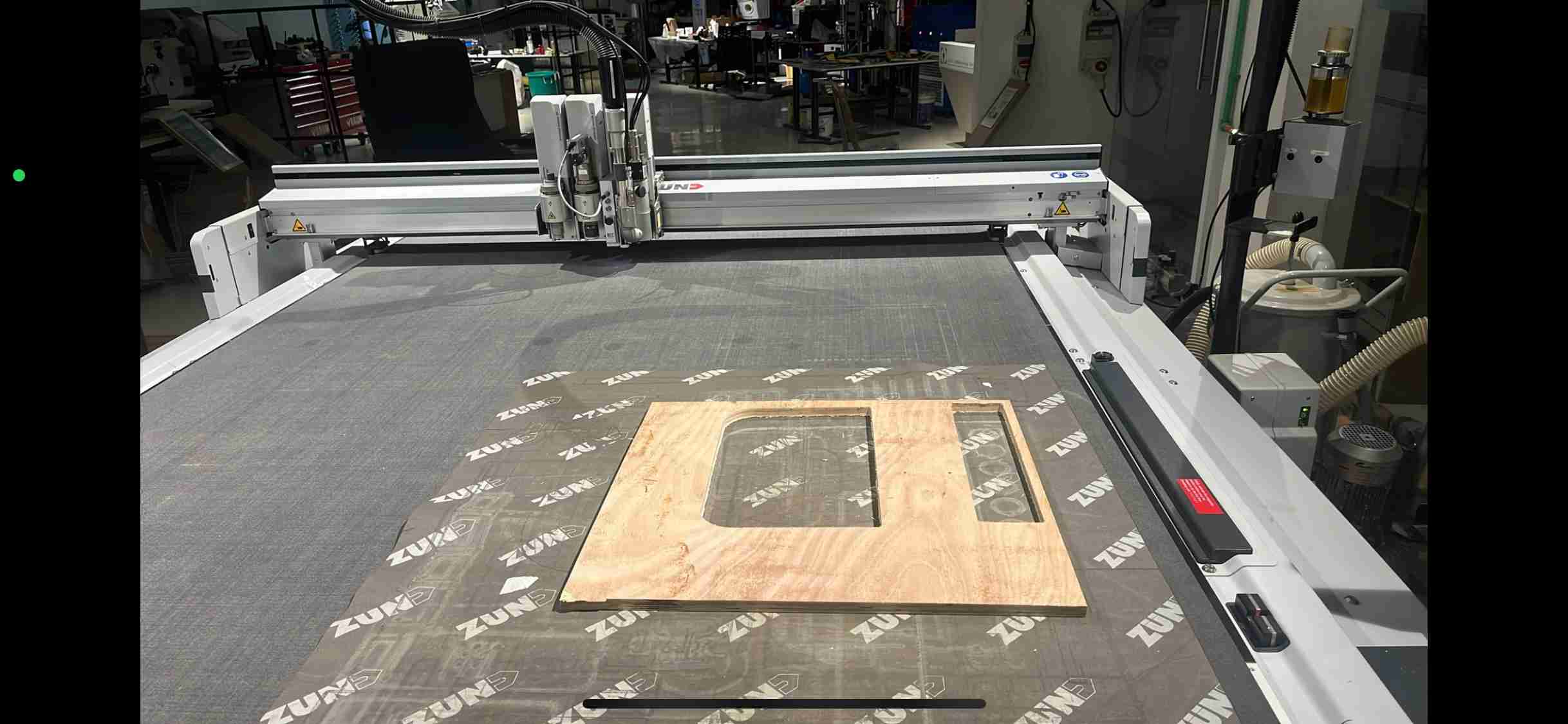
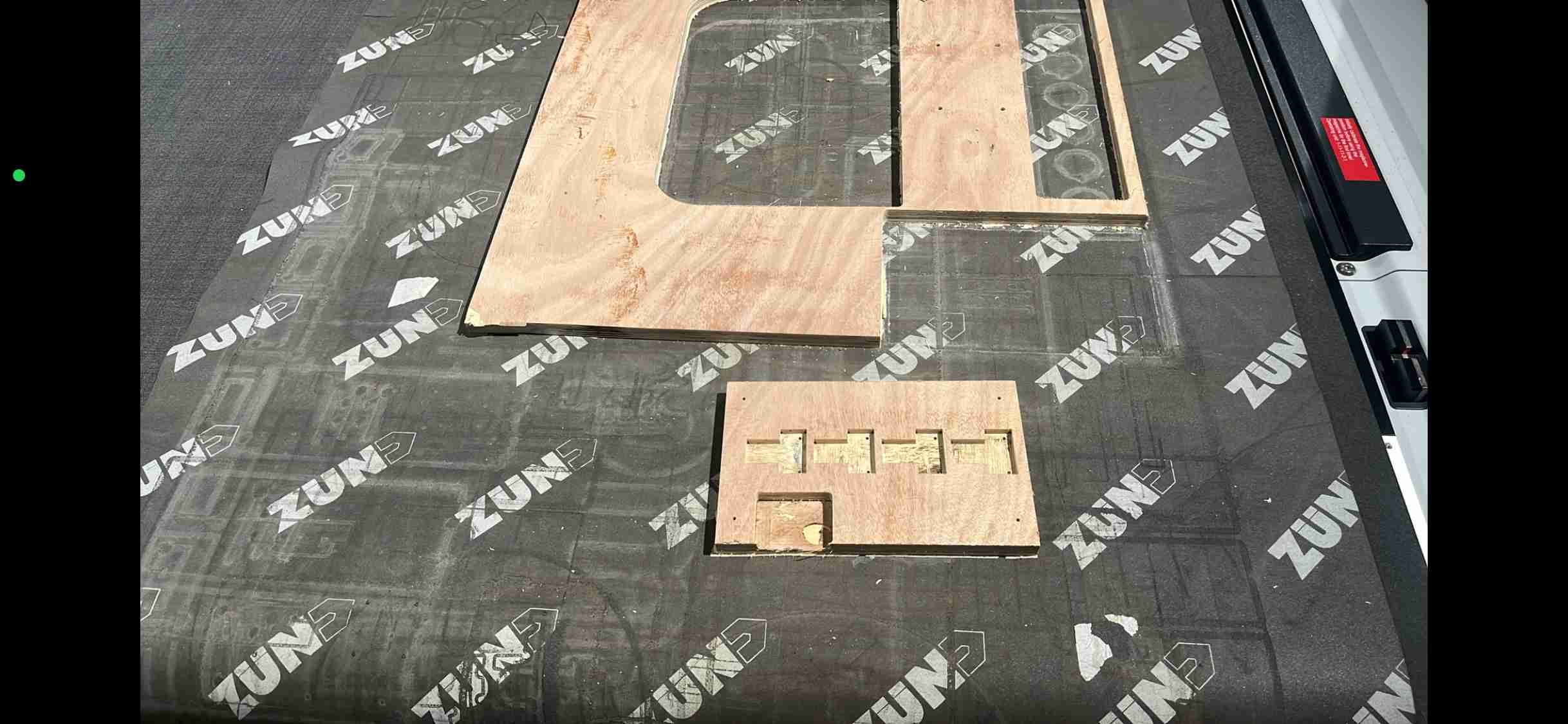
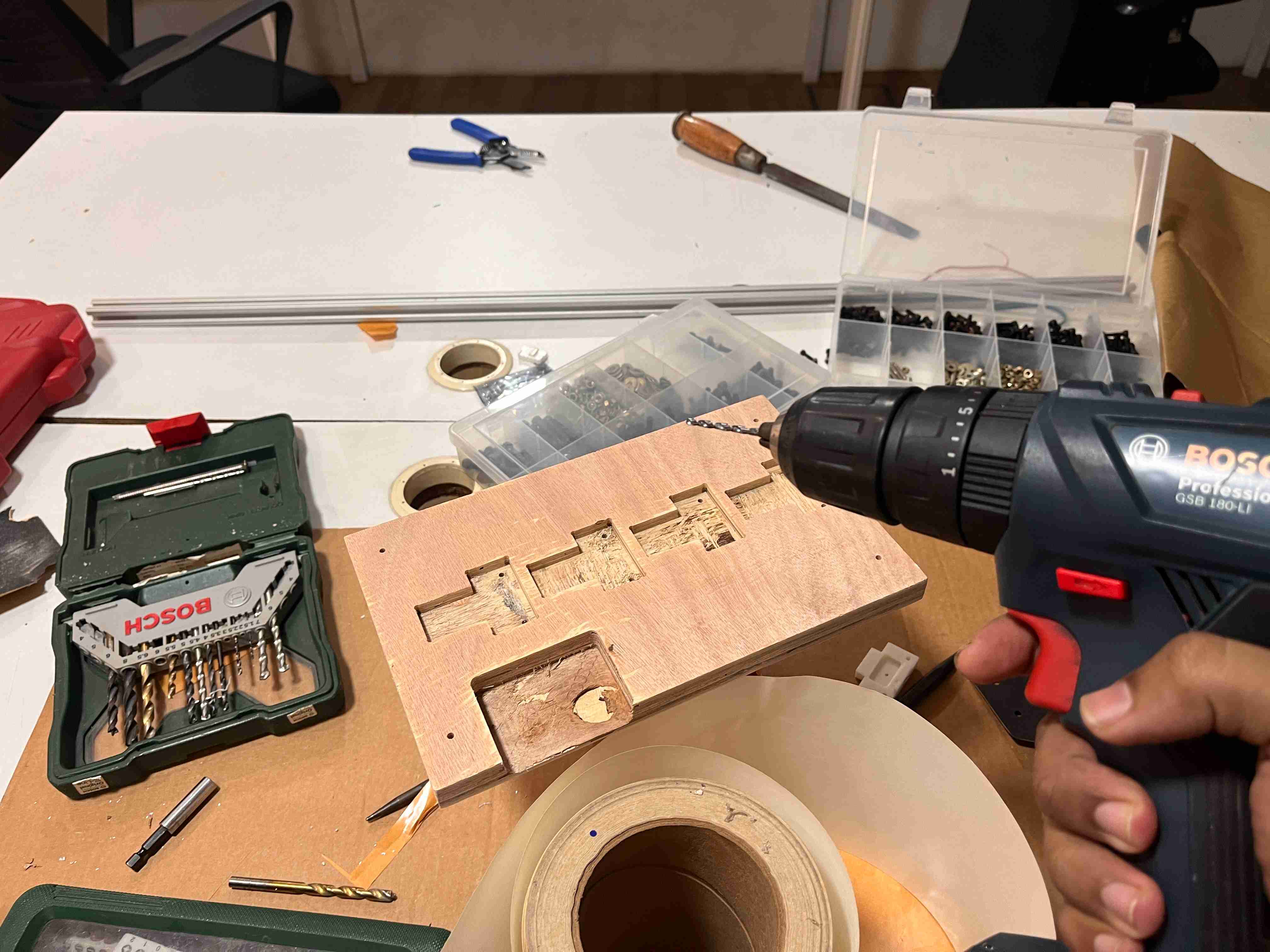
The Zund machine couldn't drill 18 mm holes with a 3 mm bit due to the bit's length. So, I manually drilled the holes using references from the gantry I printed out.
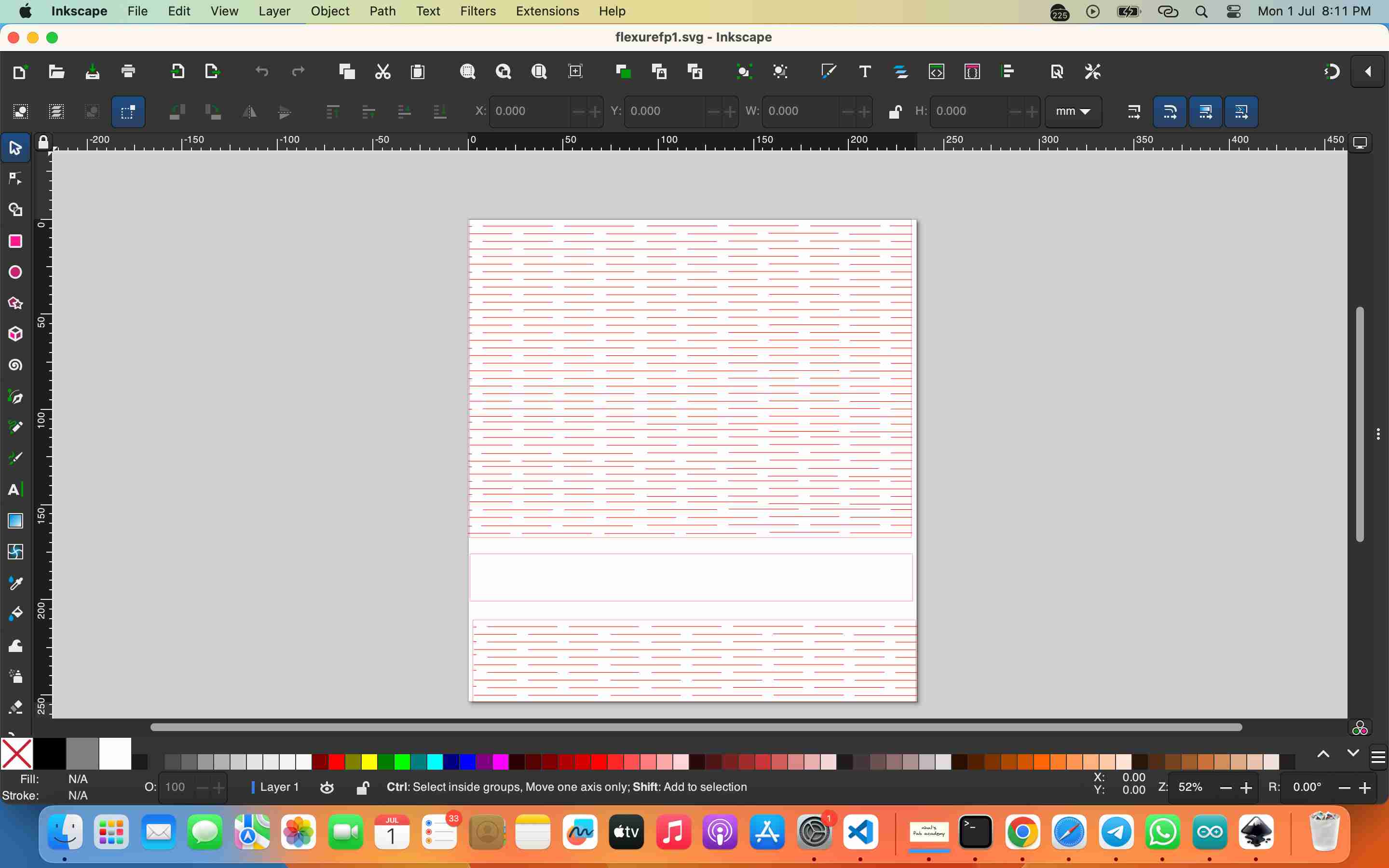
making flexures / living hinges
My design features a curved back for aesthetics, so I chose to use living hinges and flexures for the covering. I designed these in Inkscape and laser cut them. For the cutting, I used the wood settings with birch on the Trotec machine, using 3 passes at 90% power and reduced speed to achieve the desired cut.
Even though there were a lot of burn marks, it might be because the wood was very old, a leftover piece I found in the lab.
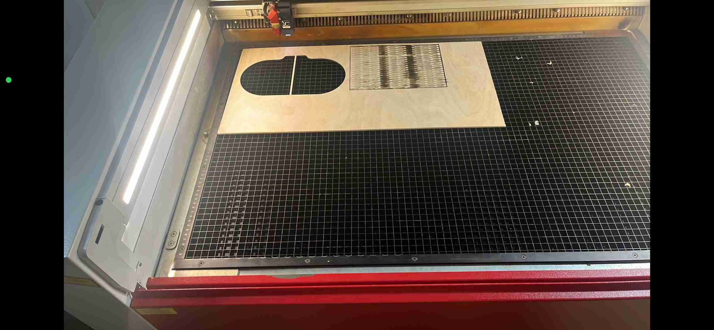
piece in the laser cutter
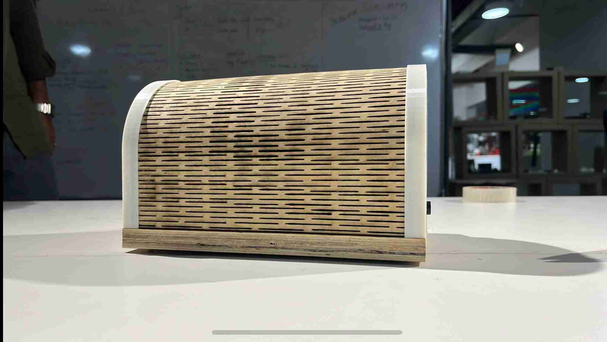
fit and aesthetic came SIMILAR to what i imagined
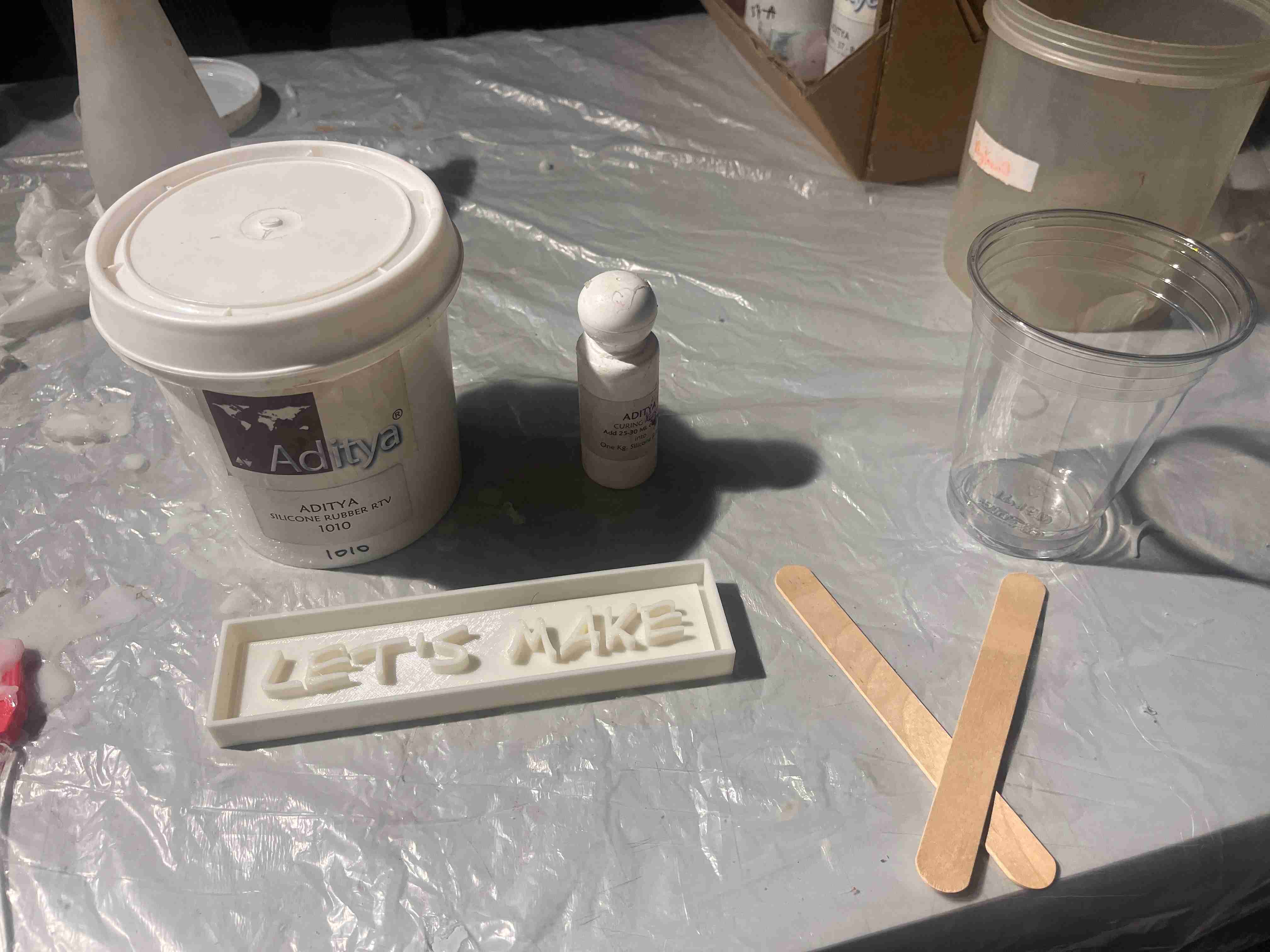
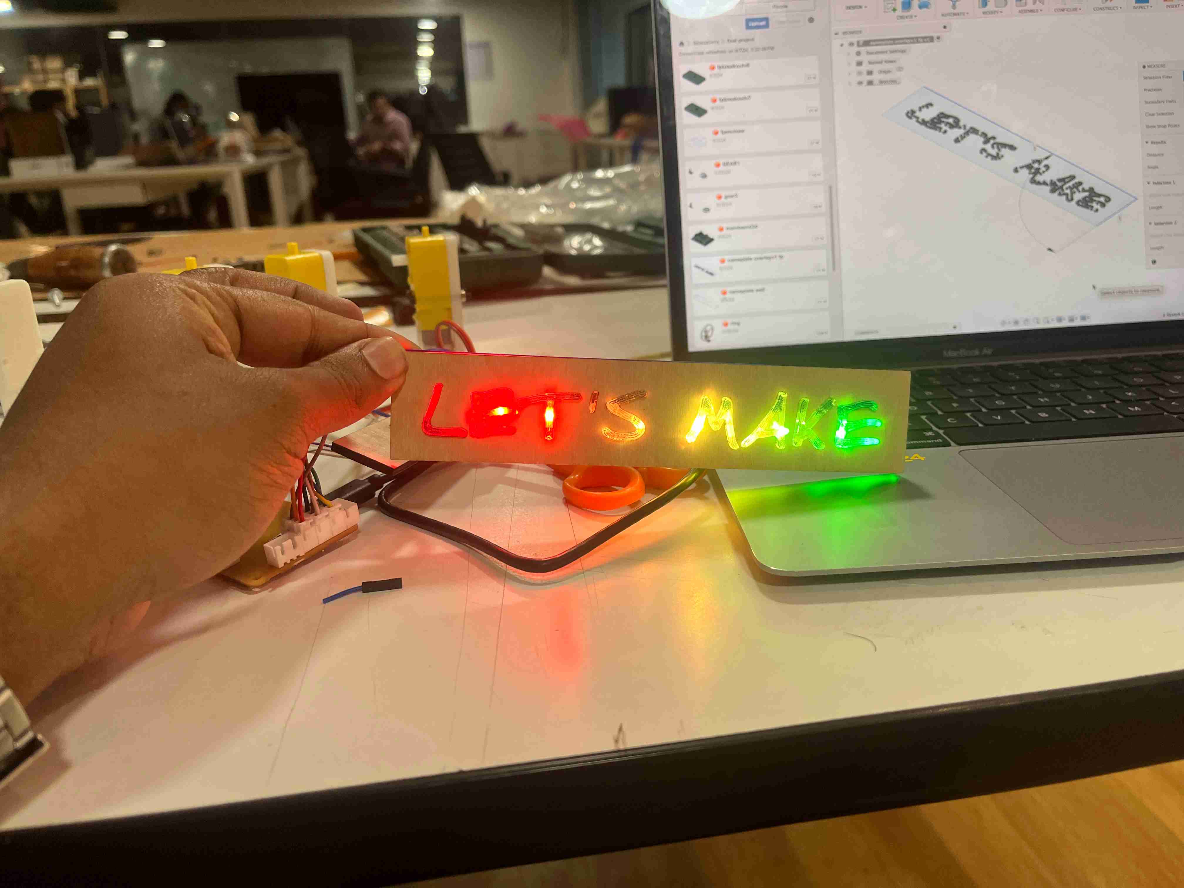
moulding the nameplate
My idea is to have a NeoPixel-embedded resin-cast nameplate at the front of the machine. I resin-cast a nameplate saying 'let's make.' First, I 3D printed the positive using FDM, then made a silicone mold. After it set, I resin-cast it, embedding the NeoPixel strip. molding ans casting is detialy documneted in WEEK 12 - Molding and Casting week.
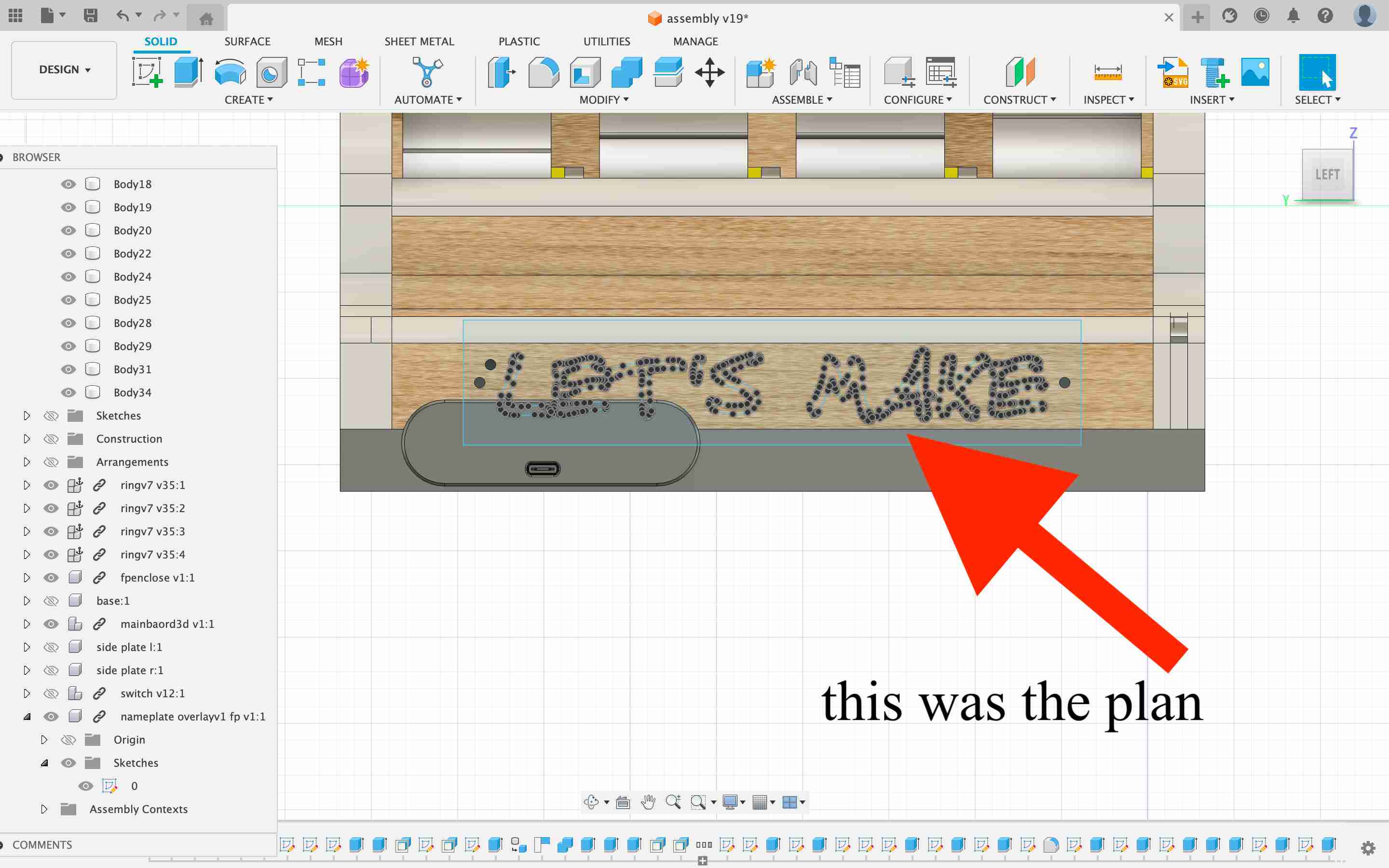
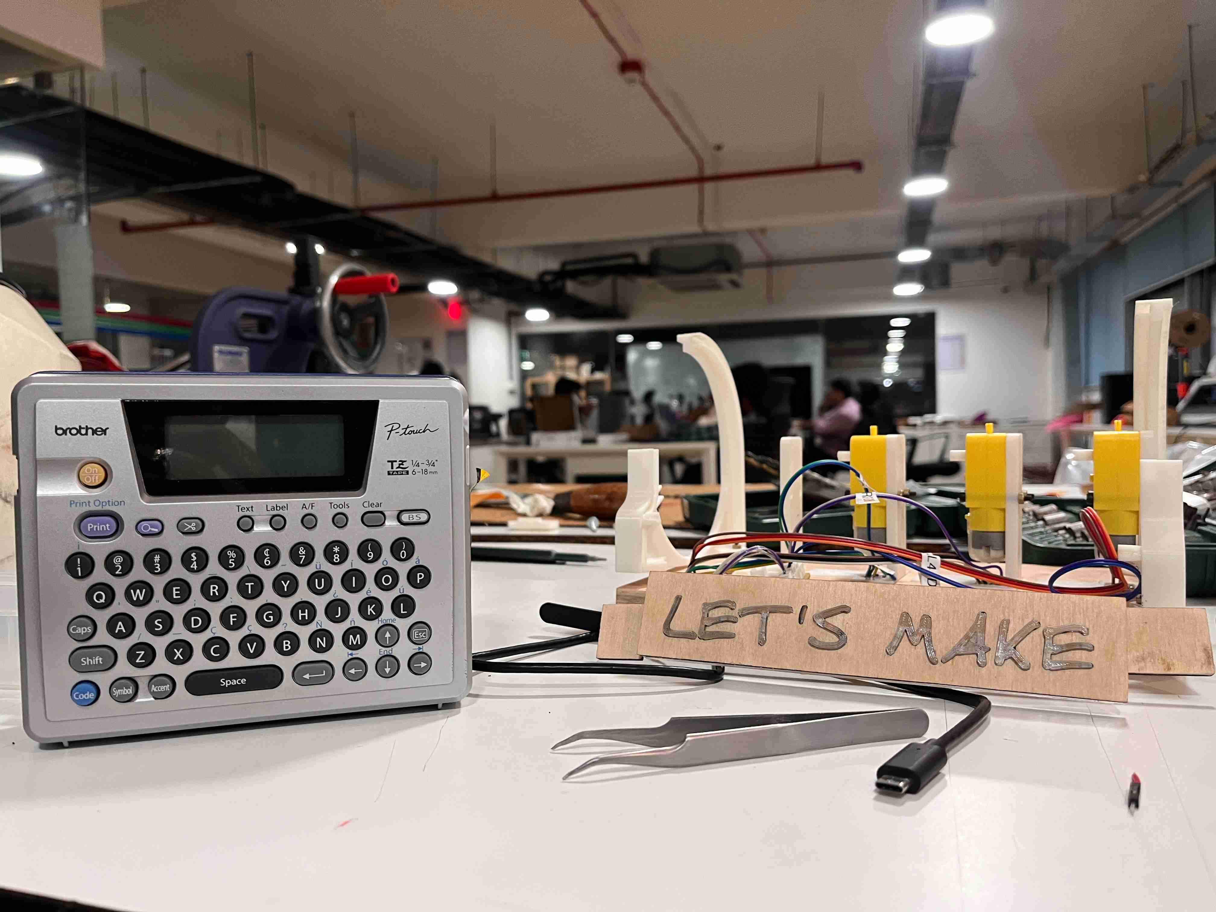
buti cameto no use as it was not fitting inside due to sapce issue . emedding it out side seem so mispalce . it was 3 days hardwork then also i removed it from final .let kae use of it anywher else
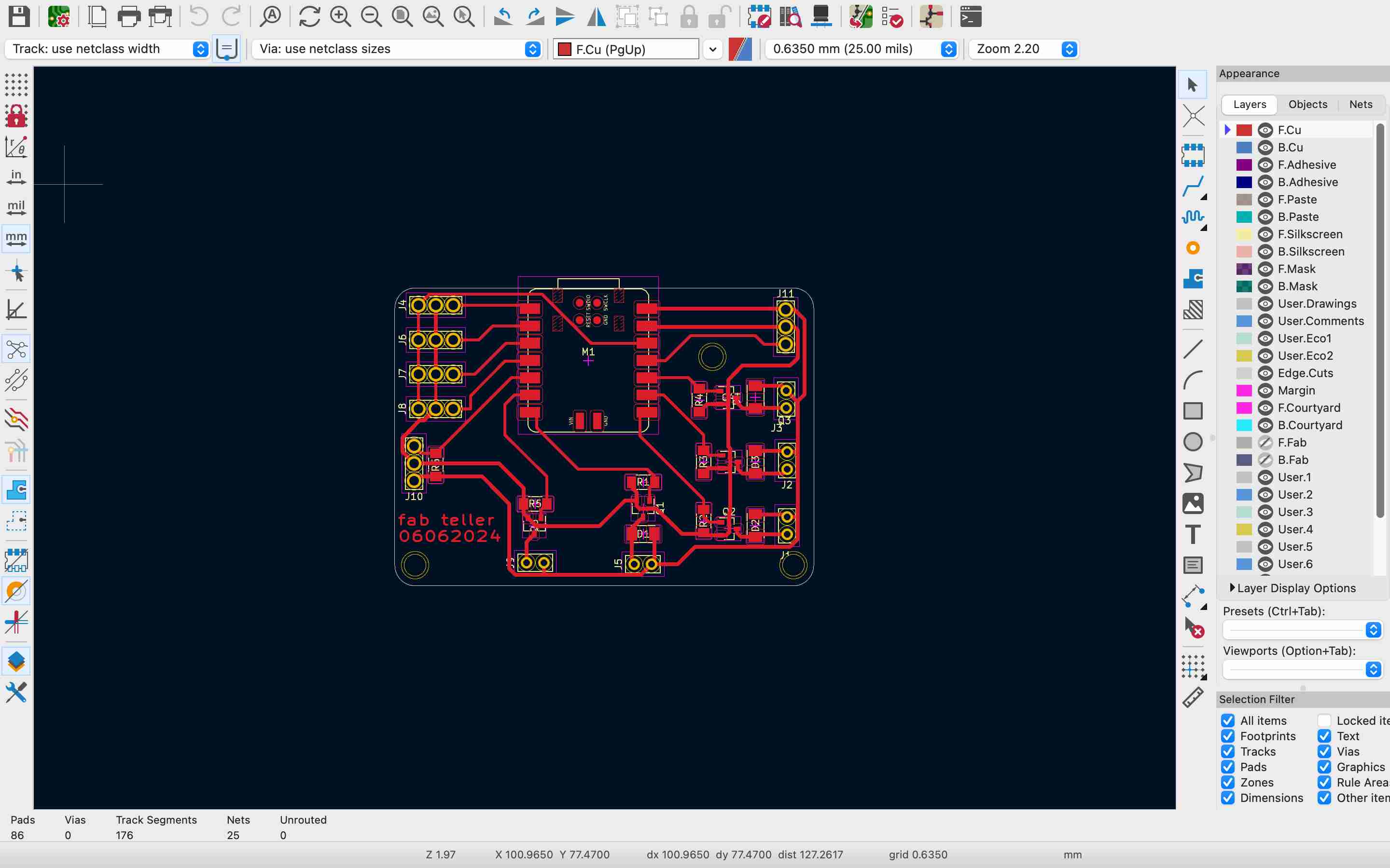
main board
When designing the main board, my initial plan was to incorporate I2C for communication between different wheel modules. However, I discovered that the Xiao board has exactly the same number of pins I needed, so I proceeded with using Xiao. I am using JST connectors to connect wires. Essentially, this board includes MOSFETs for motors, a piezo element, and necessary resistors and capacitors.
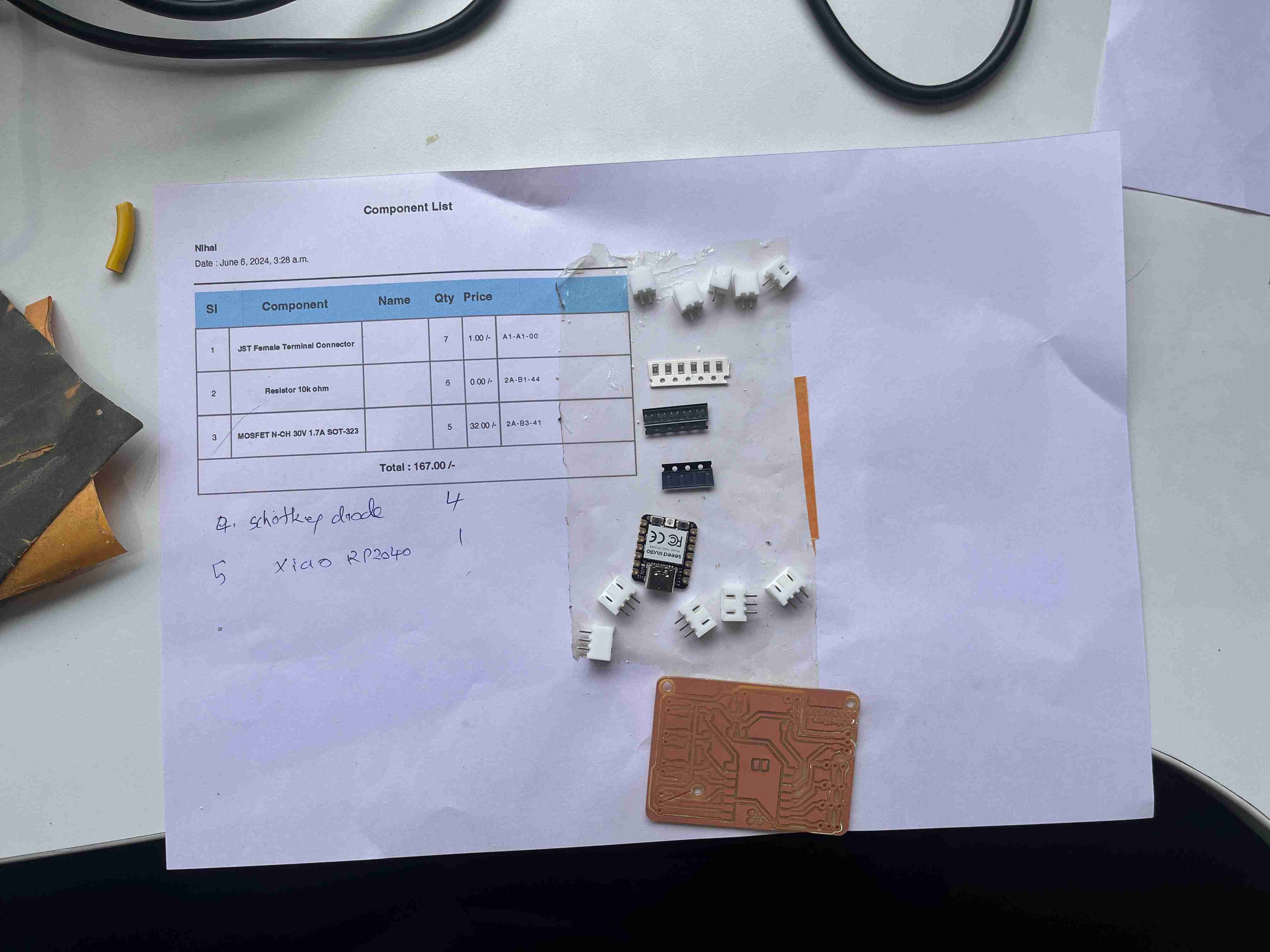
components list
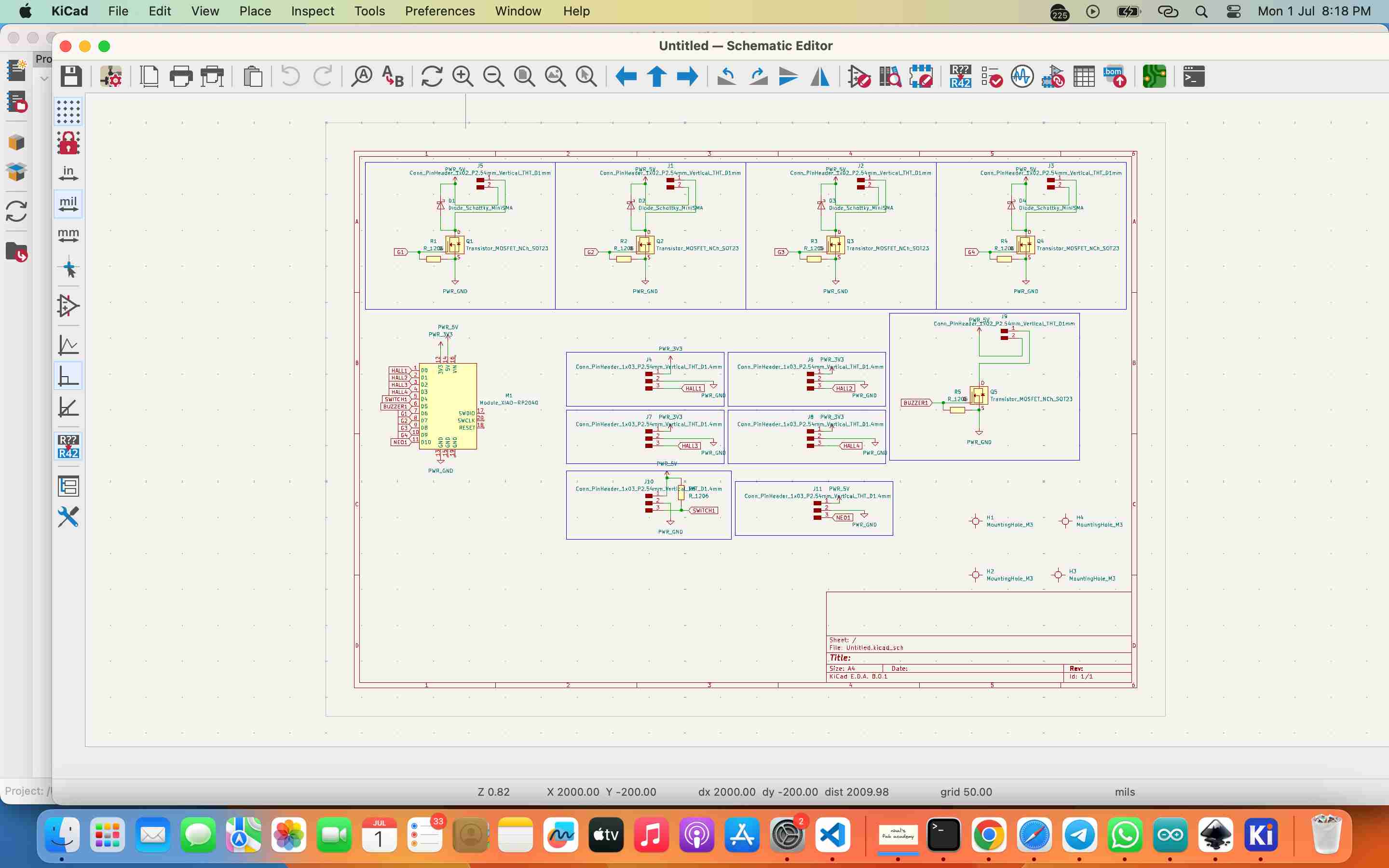
schematic diagram
pcb design and milling is DETAIL DOCUMENTED in WEEK 4 - ELECTRONICS PRODUCTION and WEEK 8 - ELECTRONICS DESIGN weeks. you can refer there
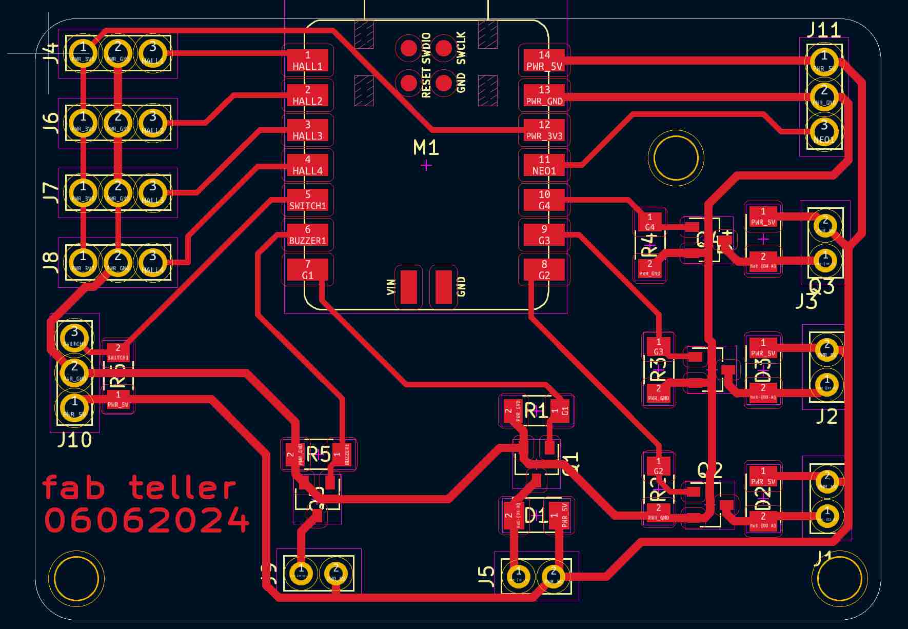
final pcb routing
xiao made the job easeri can code and power with sAME CABLE.....
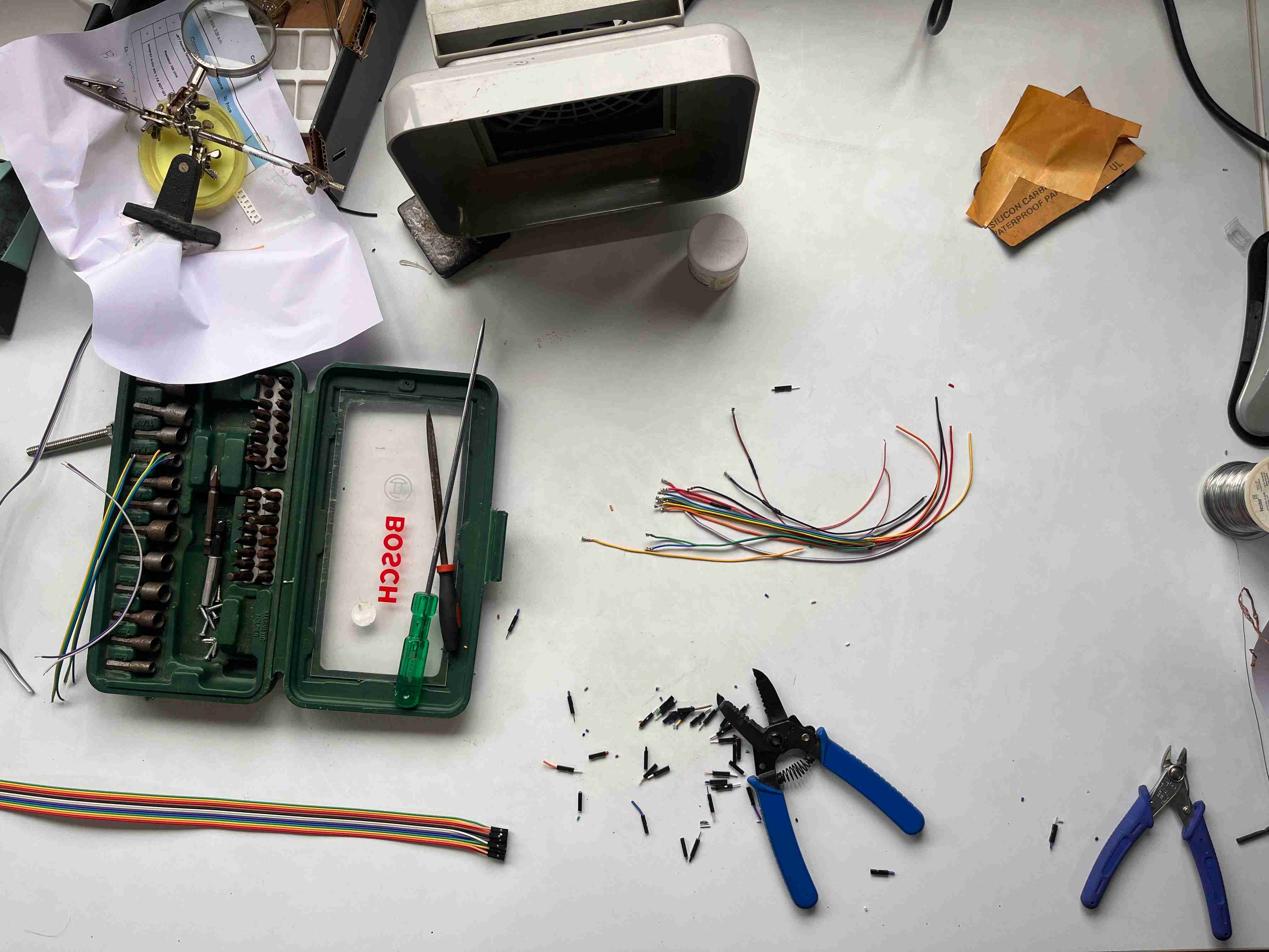
Crimping JST connectors was really a tedious task. We finally got a JST crimper, and Ryan helped me crimp all 30-plus wires.
making the cards
I explored various options for making the cards, including 3D printing and embossing. Eventually, I settled on printing the cards on photopaper available in the Fab inventory and cutting them with the help of the Zund machine. The cards and wheels are designed to be interchangeable, allowing the Fab Teller to be used for other purposes, such as casino games.
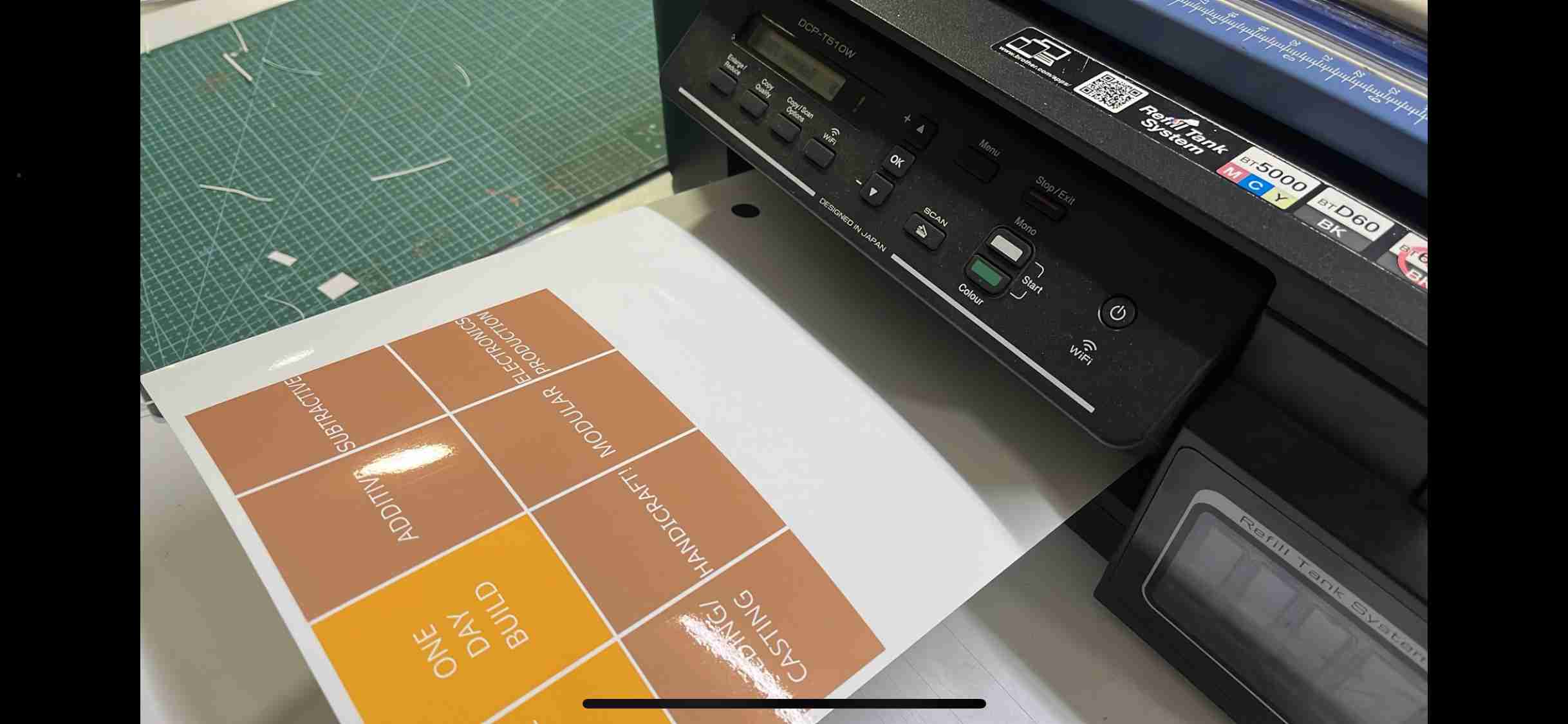
printing usign inktank printer avaialble in fab lab- designed using inkscape - glossy paper settings for printer
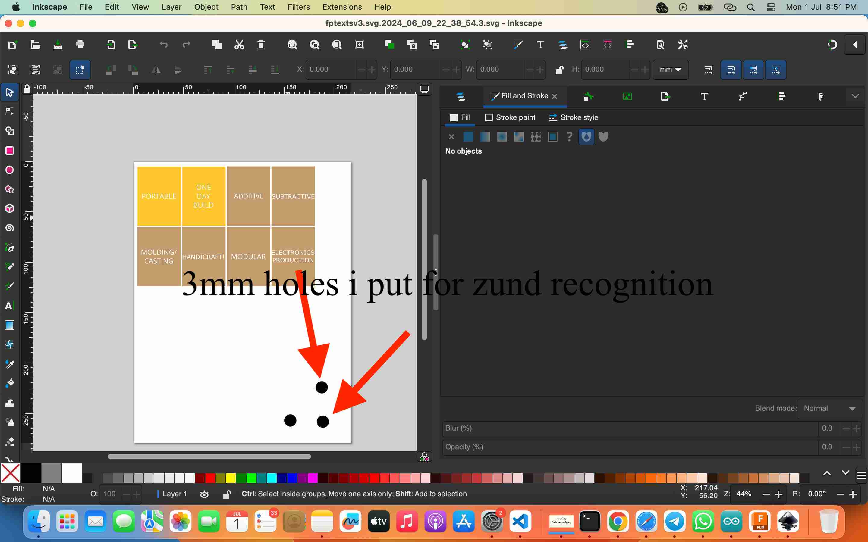
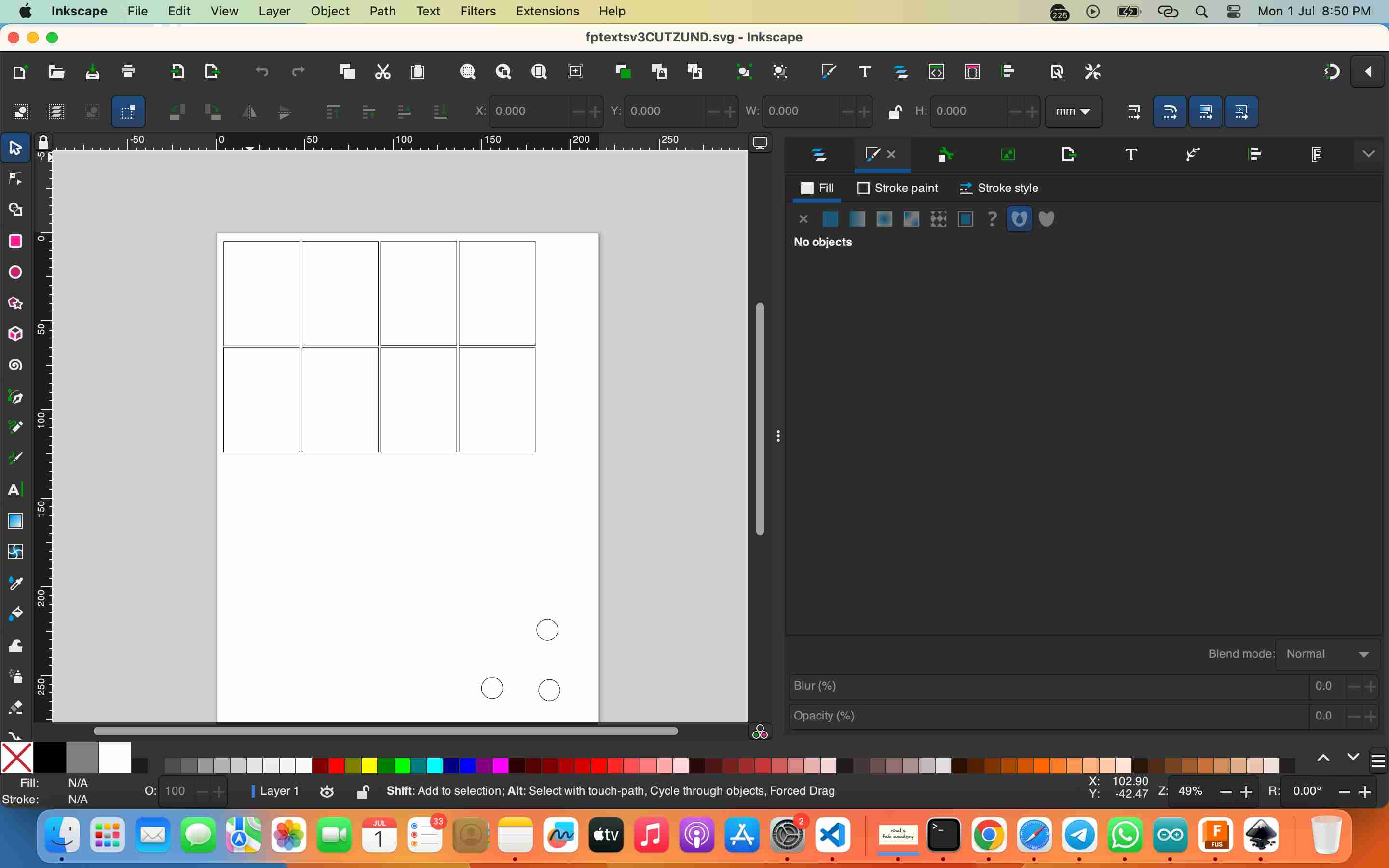
this file is the feeded to zund and 3 holes are alligned to cut prefectly
stop motion video of zund cutting
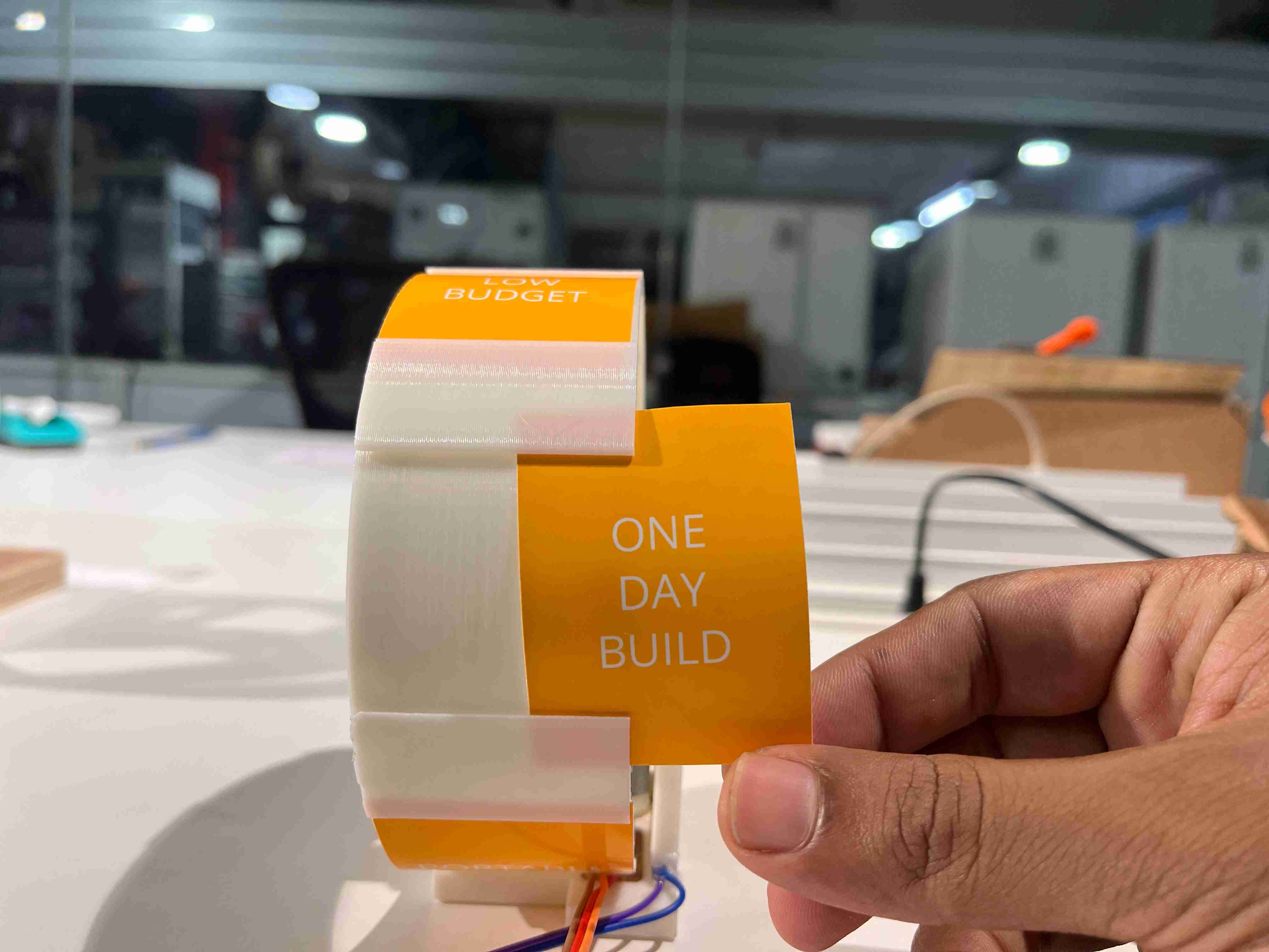
swappable cards - making the machine parametric
final prints
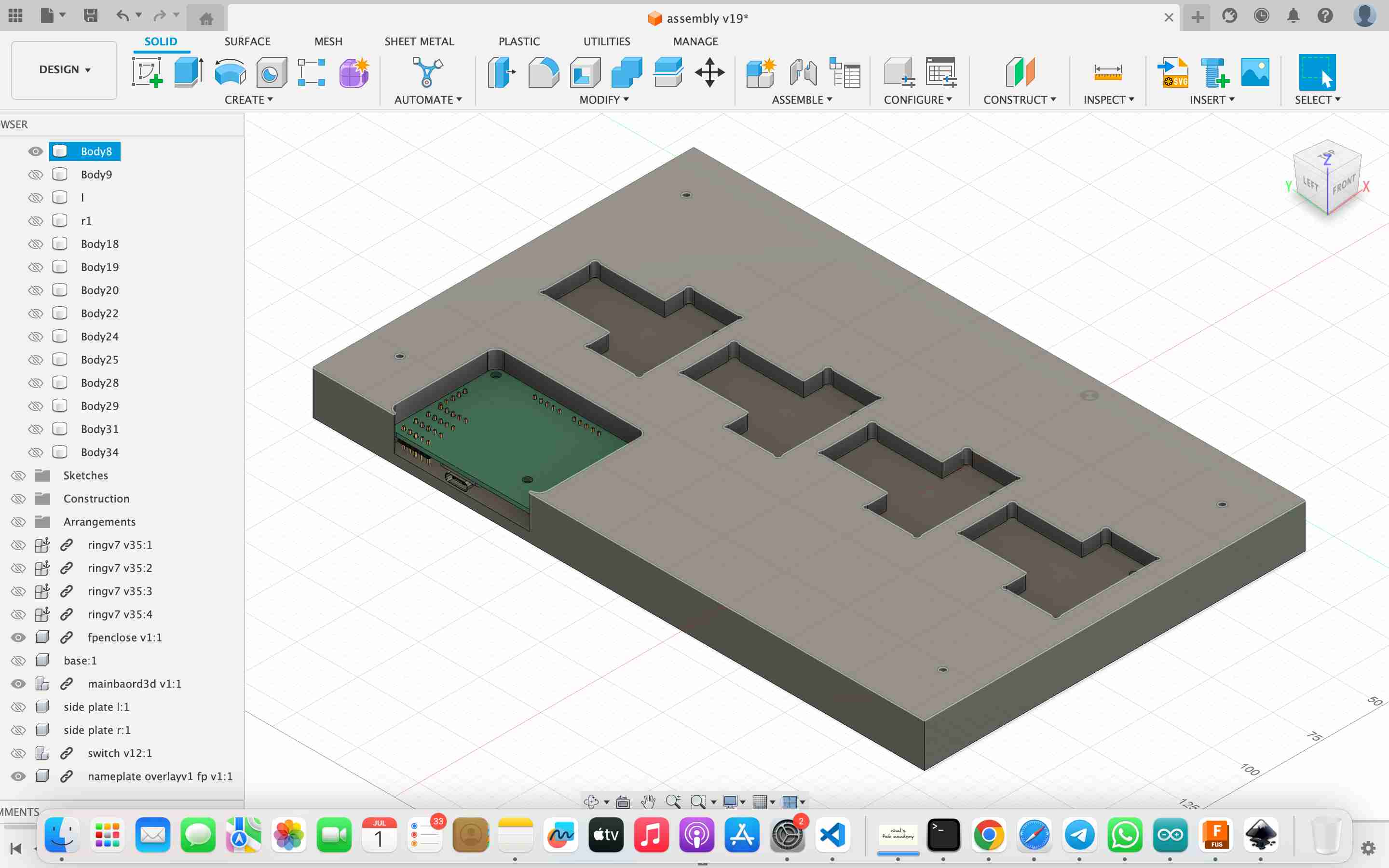
After completing the design in Fusion 360, I began printing all the parts. This followed numerous test cuts and verifications. Now, we are progressing towards the assembly stage.
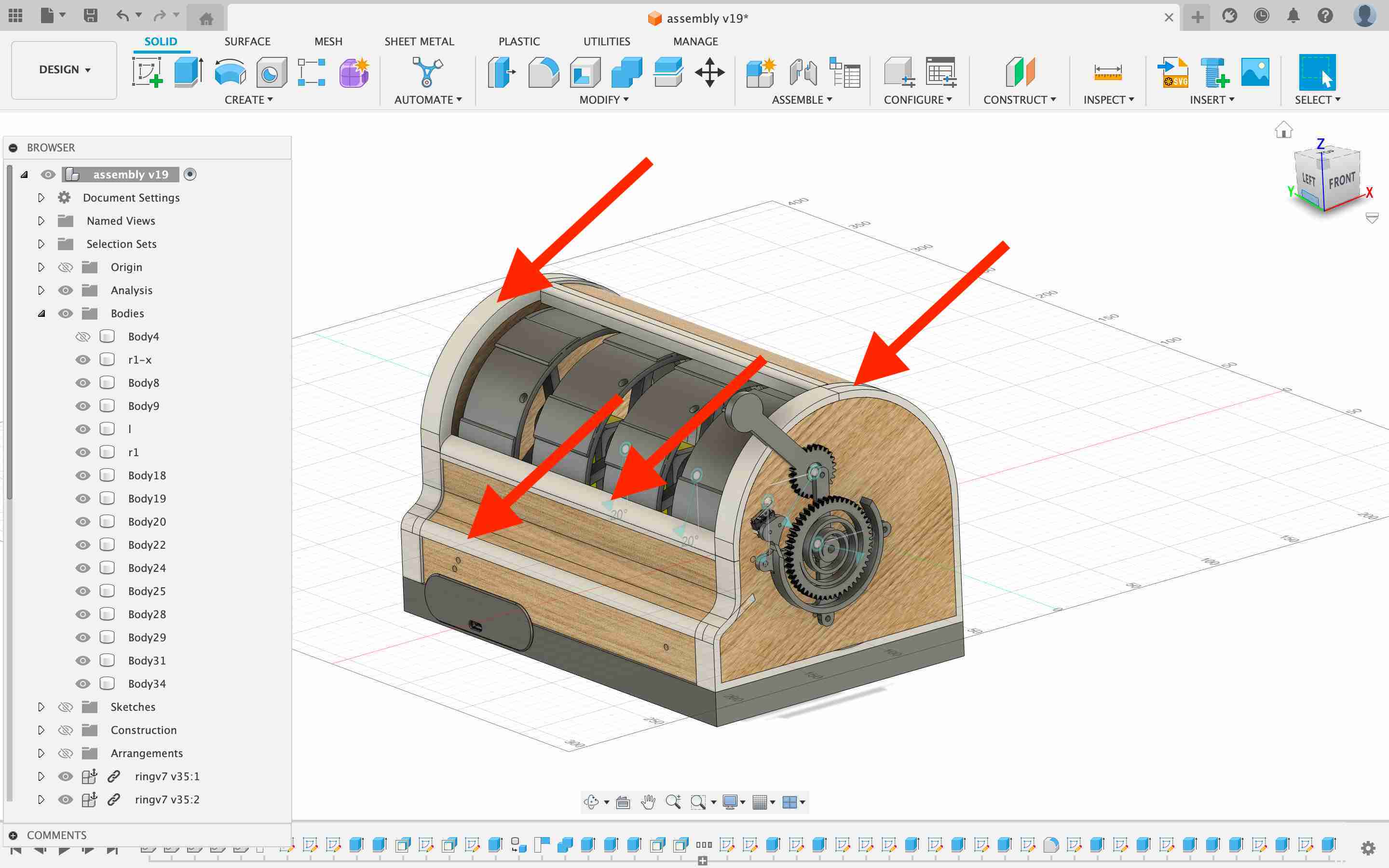
*additional parts includes all this CLADDINGS.
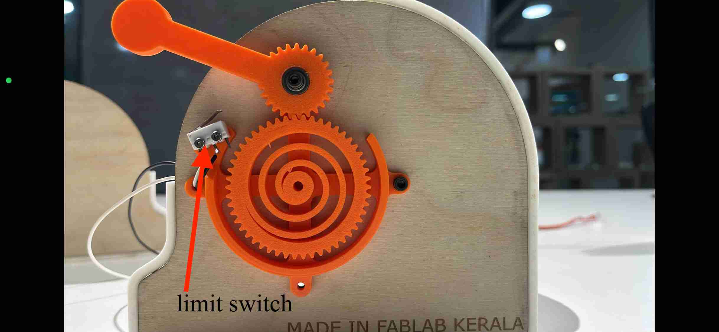
which also includes the complaint mechanism for lever attached with limit switch
final design EMBEDDED link - fusion
assembly
I started the final assembly only after completing thorough testing of each section. Alongside assembly, I made a stop-motion video, which was later embedded in the final video. Assembly went smoothly since every part had been tested and iterated upon several times beforehand.
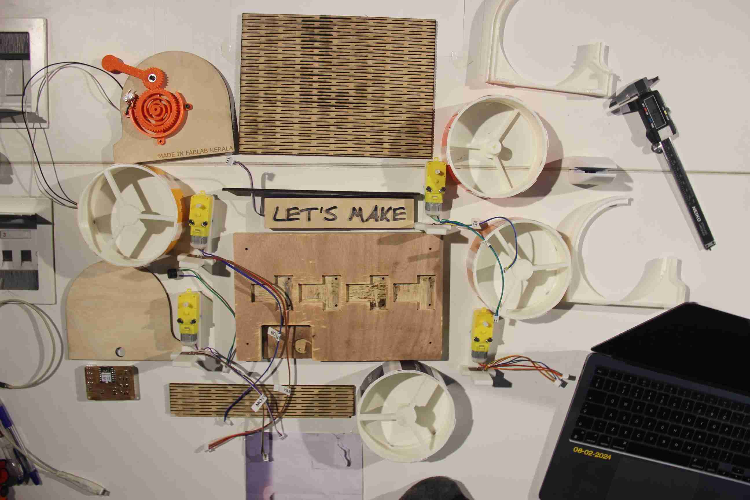
before final assembly
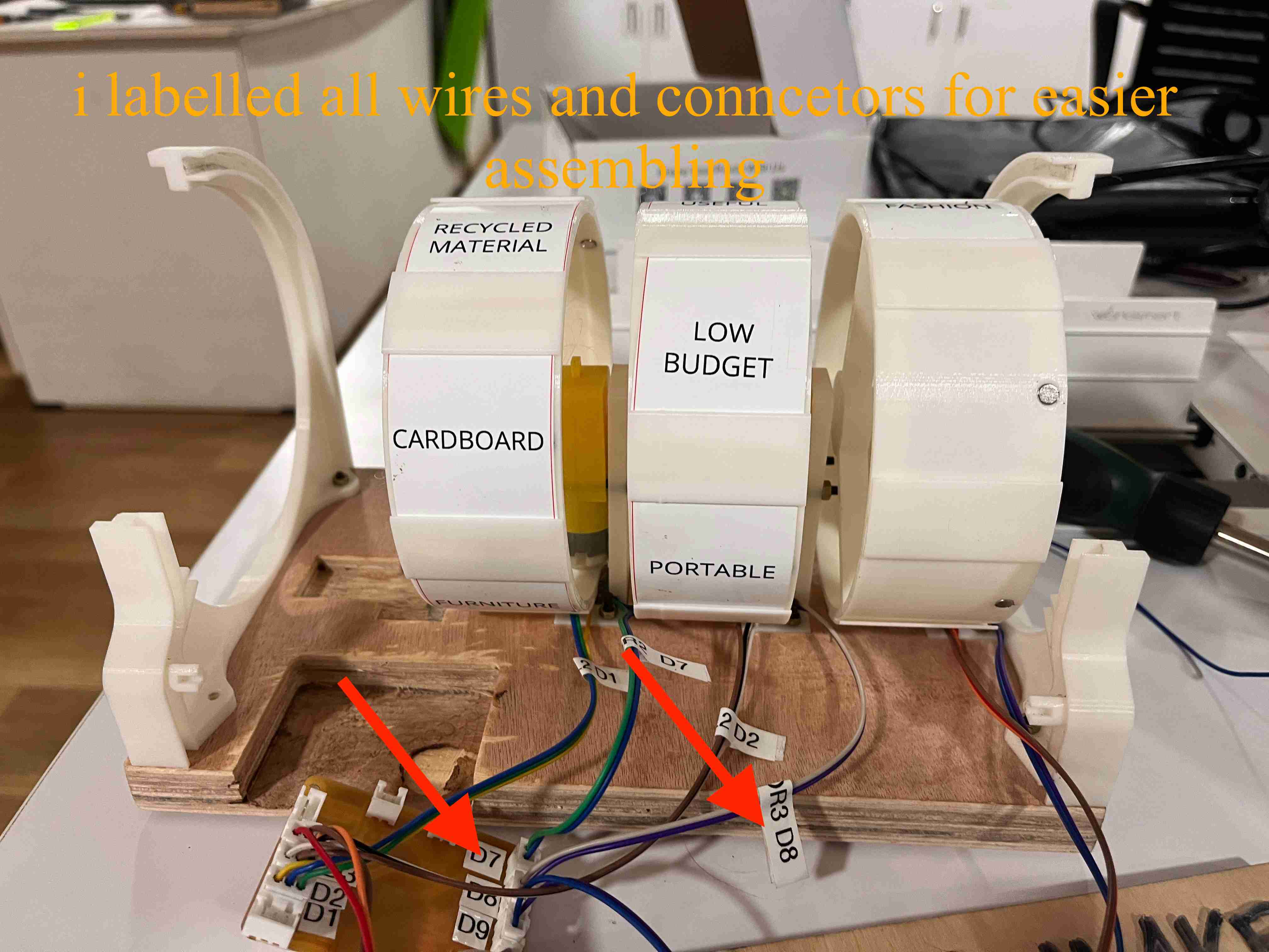
i labelled all wires and conncetors for easier assembling

me assebling the fab teller
final coding and testing
#include <Arduino.h>
// Define the pins for the hall effect sensors
const int hallEffectPins[] = {D0, D1, D2, D3};
// Define the pins for the motors
const int motorPins[] = {D6, D7, D8, D9};
// Define the pin for the switch
const int switchPin = D4;
// Number of motors and sensors
const int numMotors = 4;
// Array to store the count of magnet detections for each sensor
int magnetCounts[numMotors] = {0, 0, 0, 0};
// Array to store random stop counts for each sensor
int stopCounts[numMotors] = {0, 0, 0, 0};
// Array to track whether each sensor was already triggered
bool sensorTriggered[numMotors] = {false, false, false, false};
// Array to track whether each motor should stop
bool motorShouldStop[numMotors] = {false, false, false, false};
// Flag to indicate if the motors should start
bool startMotors = false;
// Function to initialize random stop counts for each motor
void initializeStopCounts() {
for (int i = 0; i < numMotors; i++) {
stopCounts[i] = random(1, 10); // Random stop count between 1 and 10
}
}
// Function to check if all motors have stopped
bool allMotorsStopped() {
for (int i = 0; i < numMotors; i++) {
if (!motorShouldStop[i]) {
return false;
}
}
return true;
}
void setup() {
// Initialize serial communication
Serial.begin(9600);
// Set the hall effect sensor pins as input
for (int i = 0; i < numMotors; i++) {
pinMode(hallEffectPins[i], INPUT);
}
// Set the motor pins as output and turn off the motors
for (int i = 0; i < numMotors; i++) {
pinMode(motorPins[i], OUTPUT);
digitalWrite(motorPins[i], LOW); // Stop the motors initially
}
// Set the switch pin as input with internal pull-up resistor
pinMode(switchPin, INPUT_PULLUP);
// Initialize random seed
randomSeed(analogRead(A0));
// Initialize random stop counts for each motor
initializeStopCounts();
}
void loop() {
// Check if switch is activated (LOW state) and motors are not yet started
if (digitalRead(switchPin) == LOW && !startMotors) {
// Start all motors
for (int i = 0; i < numMotors; i++) {
digitalWrite(motorPins[i], HIGH);
motorShouldStop[i] = false; // Reset the stop flags
magnetCounts[i] = 0; // Reset the magnet counts
}
Serial.println("Motors started!");
startMotors = true;
}
// If motors are running, check for magnet detection and stop conditions
if (startMotors) {
// Loop through each sensor
for (int i = 0; i < numMotors; i++) {
// Read the state of the hall effect sensor
int sensorState = digitalRead(hallEffectPins[i]);
// If the sensor detects a magnet (LOW state) and it wasn't triggered before
if (sensorState == LOW && !sensorTriggered[i]) {
// Increment the magnet count for the corresponding sensor
magnetCounts[i]++;
// Print the current magnet count for the corresponding sensor
Serial.print("Magnet detected on sensor ");
Serial.print(i + 1);
Serial.print("! Count: ");
Serial.println(magnetCounts[i]);
// Check if the magnet count has reached the random stop count
if (magnetCounts[i] >= stopCounts[i]) {
// Stop the corresponding motor
Serial.print("Stopping motor ");
Serial.print(i + 1);
Serial.print(" at magnet count ");
Serial.println(magnetCounts[i]);
digitalWrite(motorPins[i], LOW);
motorShouldStop[i] = true;
Serial.print("Motor ");
Serial.print(i + 1);
Serial.println(" stopped!");
}
// Set the sensor triggered flag to true for the corresponding sensor
sensorTriggered[i] = true;
}
// If the sensor is not detecting a magnet (HIGH state)
// reset the sensor triggered flag to false for the corresponding sensor
if (sensorState == HIGH) {
sensorTriggered[i] = false;
}
}
// Check if all motors have stopped
if (allMotorsStopped()) {
Serial.println("All motors stopped. Waiting for next switch activation...");
// Reset startMotors flag
startMotors = false;
// Re-initialize random stop counts for the next round
initializeStopCounts();
}
}
// A short delay to prevent rapid counting due to sensor noise
delay(100);
}
code testing
-
Constants and Variables Initialisation:
hallEffectPins[]: Defines pins connected to Hall effect sensors for detecting magnets.motorPins[]: Pins connected to motors for control.switchPin: Pin for an external switch to start the motors.- Arrays and flags (
magnetCounts[],stopCounts[],sensorTriggered[],motorShouldStop[],startMotors): Used for tracking magnet detections, random stop counts, sensor triggers, motor stop conditions, and motor start status.
-
Setup Function (
setup()):- Initialises serial communication for debugging.
- Configures sensor pins as inputs, motor pins as outputs, and initialises motors as stopped.
- Sets up the switch pin with an internal pull-up resistor.
- Initialises the random seed for generating stop counts.
-
Loop Function (
loop()):- Checks if the switch is activated (
LOWstate) and motors are not started (startMotorsisfalse). If true, starts all motors and resets necessary variables. - When motors are started (
startMotorsistrue):- Iterates through each sensor to check for magnet detection (
LOWstate). - Increments
magnetCounts[]for detected magnets and prints the count. - Compares
magnetCounts[]withstopCounts[]to stop motors when the count reaches the random stop count for each motor. - Sets flags (
sensorTriggered[]) to manage multiple detections. - Checks if all motors have stopped (
allMotorsStopped()function). - Resets
startMotorstofalseand initialises new random stop counts for the next cycle.
- Iterates through each sensor to check for magnet detection (
- Checks if the switch is activated (
-
Functions (
initializeStopCounts(),allMotorsStopped()):initializeStopCounts(): Initialises random stop counts for each motor.allMotorsStopped(): Checks if all motors have stopped based onmotorShouldStop[]flags.
-
Serial Communication:
- Outputs status messages and debugging information via Serial Monitor for monitoring sensor detections, motor stops, and system states.
I modified the code several times using different combinations to improve its functionality. However, further refinement is still needed to optimize its performance.
code testing limit switch in action
result
The final code was completed with assistance from Jogin, as I encountered difficulties with smooth ramping up and down of motor speeds and stopping precisely at exact positions. Although it still requires further refinement due to time constraints for the presentation, we decided to proceed with it.
// Define motor control pins (PWM-capable)
const int motor1Pin = 3; // Ensure these are PWM-capable pins
const int motor2Pin = 5;
const int motor3Pin = 6;
const int motor4Pin = 9;
// Define Hall effect sensor pins
const int hallSensor1Pin = 6;
const int hallSensor2Pin = 7;
const int hallSensor3Pin = 8;
const int hallSensor4Pin = 9;
// Define switch pin
const int switchPin = 10;
// Define magnet counts for each motor
const unsigned long motor1Count = 15;
const unsigned long motor2Count = 20;
const unsigned long motor3Count = 10;
const unsigned long motor4Count = 30;
// Variables to store counts
unsigned long count1 = 0;
unsigned long count2 = 0;
unsigned long count3 = 0;
unsigned long count4 = 0;
// Variable to track previous sensor states
int prevSensor1State = LOW;
int prevSensor2State = LOW;
int prevSensor3State = LOW;
int prevSensor4State = LOW;
// Array to store PWM values for motors
int mot_pwm[] = {55, 255, 255, 255}; // Initial PWM values
// Function to rotate motor until the specified magnet count is reached
void rotateMotor(int motorPin, int sensorPin, unsigned long targetCount, unsigned long &count, int &prevSensorState, int pwmValue) {
analogWrite(motorPin, pwmValue); // Set motor speed to specified duty cycle
while (count < targetCount) {
int sensorState = digitalRead(sensorPin);
if (sensorState == HIGH && prevSensorState == LOW) {
count++;
}
prevSensorState = sensorState;
}
analogWrite(motorPin, 0); // Stop the motor
}
void setup() {
// Initialize motor pins as outputs
pinMode(motor1Pin, OUTPUT);
pinMode(motor2Pin, OUTPUT);
pinMode(motor3Pin, OUTPUT);
pinMode(motor4Pin, OUTPUT);
// Initialize Hall effect sensor pins as inputs
pinMode(hallSensor1Pin, INPUT);
pinMode(hallSensor2Pin, INPUT);
pinMode(hallSensor3Pin, INPUT);
pinMode(hallSensor4Pin, INPUT);
// Initialize switch pin as input with pull-up resistor
pinMode(switchPin, INPUT_PULLUP);
// Seed the random number generator
randomSeed(analogRead(0));
}
void loop() {
// Check if the switch is pressed
if (digitalRead(switchPin) == LOW) {
// Reset counts
count1 = 0;
count2 = 0;
count3 = 0;
count4 = 0;
// Array of motor and sensor pins
int motorPins[] = {motor1Pin, motor2Pin, motor3Pin, motor4Pin};
int sensorPins[] = {hallSensor1Pin, hallSensor2Pin, hallSensor3Pin, hallSensor4Pin};
unsigned long targetCounts[] = {motor1Count, motor2Count, motor3Count, motor4Count};
unsigned long *counts[] = {&count1, &count2, &count3, &count4};
int *prevStates[] = {&prevSensor1State, &prevSensor2State, &prevSensor3State, &prevSensor4State};
// Update PWM values as needed
mot_pwm[0] = 55;
mot_pwm[1] = 255;
mot_pwm[2] = 255;
mot_pwm[3] = 255;
// Rotate each motor with the specified PWM value
for (int i = 0; i < 4; i++) {
rotateMotor(motorPins[i], sensorPins[i], targetCounts[i], *counts[i], *prevStates[i], mot_pwm[i]);
}
// Wait until the switch is released
while (digitalRead(switchPin) == LOW);
}
}
// Function to swap two elements
template <typename T>
void swap(T &a, T &b) {
T temp = a;
a = b;
b = temp;
}
the code
- pin Definitions:
- Motor control pins (
motor1Pintomotor4Pin) and corresponding Hall effect sensor pins (hallSensor1PintohallSensor4Pin) are defined. switchPinis set for detecting the activation of a switch to start the motors.
- Motor control pins (
- Constants:
motor1Counttomotor4Countspecify the target magnet counts for each motor to rotate before stopping.- Initial counts (
count1tocount4) and previous sensor states (prevSensor1StatetoprevSensor4State) are initialized.
- PWM Values:
mot_pwm[]holds initial PWM values for each motor.
- Functions:
rotateMotor(): Controls motor rotation until the specified magnet count (targetCount) is reached. It adjusts motor speed with PWM (pwmValue) and tracks sensor states to count magnets.swap(): A generic function to swap two elements, though it appears unused in the provided code.
- Setup Function (
setup()):- Configures motor and sensor pins as outputs and inputs respectively.
- Sets up the switch pin with a pull-up resistor for detecting low state (pressed switch).
- Loop Function (
loop()):- Checks if the switch is pressed (
LOWstate). - If pressed, resets counts and initiates motor rotation using
rotateMotor()for each motor. Each motor runs until it reaches its designated magnet count. - Updates PWM values (
mot_pwm[]) as needed based on conditions. - Waits until the switch is released (
HIGHstate) before repeating the process.
- Checks if the switch is pressed (
final result
design files
i am all files required to replicate this project as zip
bill of materials
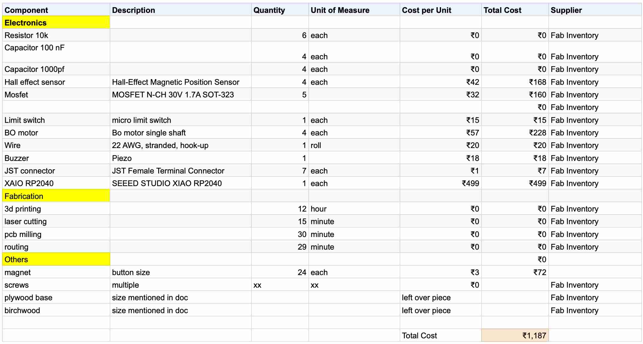
my bOM IS 1187 INDIAN RUPEE WHICH IS APPROX 14 DOLLARS.
This project demonstrates that it's possible to build a functional and innovative solution within a tight budget.

license
fab teller © 2024 by muhammad nihal chettiyam veettil is licensed under CC BY 4.0. To view a copy of this license, visit https://creativecommons.org/licenses/by/4.0/