Mechanical Design & Machine Design
Objectives for Week 10
- Group Assignment:
- Design a machine that includes mechanism + actuation + automation + application
- Build the mechanical parts and operate it manually
- Actuate and automate the machine
- Document individual contribution
For this week, the assignment is to build a machine. Since, the total strength of this year's class is 10, we were divided into two groups containing 5 members each. We started planning on what to make almost a week ahead. And it also took us the same time to finalize on the idea.
Our idea is to create a machine that can cut a cake into instructed number of pieces of equal quantity. This idea arose when we had a birthday celebration here at FabLab and the cake was cut into random sizes and everyone was disatisfied with their share. So having a cake cutter gives a proper need and creating such a machine could add in to the fun.
This week I will be documenting all the work I have done during the process.
On the first day we had a meeting to understand all the works that will be involved and on how to split the job. I led the designing part of the project. There are two main design features: Cutting Mechanism and Turn Table Mechanism. I took up the cutting mechanism.
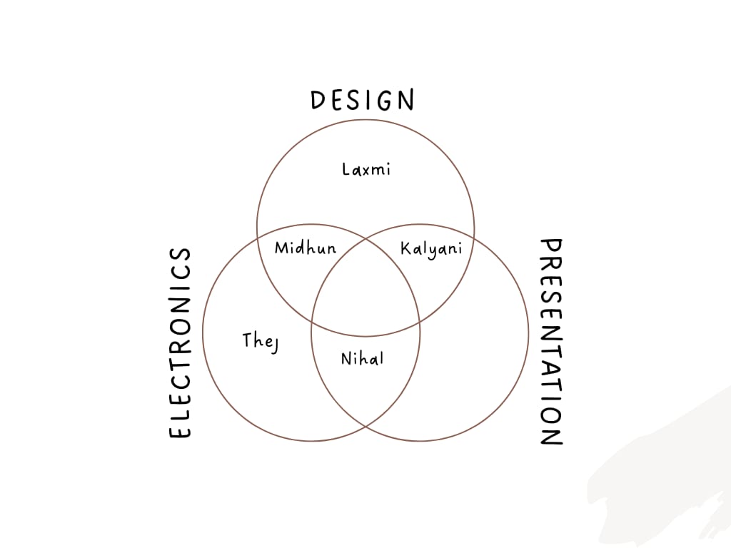
• Refer Nihal's documentation for details on Project Management.
• Refer Midhun's documentation for details on Turn Table Design.
• Refer Kalyani's documentation for details on Concept sketch and Poster.
• Refer Thej's documentation for details on Programming and Interface.
At first, we wanted to incorporate conventional link mechanism for the cutting. I was introduced to MotionGen by our instructor, Mufeed. MotionGen is an online platform where the creator can design, animate and prototype any mechanisms.
I gave a simple path on how the blade should move and synthesized the links. I received almost 30 different link placements but I realized a problem. MotionGen only gives movements in organic shapes instead of producing sharp movements and this was not the case we require. Soon, I dropped the idea.
There were some parameters I had to consider while designing.
- The length of the blade should be half so that it cuts the cake right to its centre. The reason being, we will be able to cut odd number of slices from the cake.
- The mechanism should be able to cut a cake with maximum height of 15cm.
- The bed size was fixed to 25cm, hence, the length of the knife should be accordingly.
Design 1
Before moving directly to designing, I first researched on different cutting mechanisms applicable for cake cutting and I came across an interesting method of using slider-crank mechanism for cutting. Click on the link to watch the video.
Cake Cutting MechanismInspired by the video, I created a similar mechanism.
Here's a structure that I designed in fusion to show the working mechanism. But the issue was that the diameter of the circle will increase as the linear distance that should be covered by the blade, therefore, the design may look so bulky.
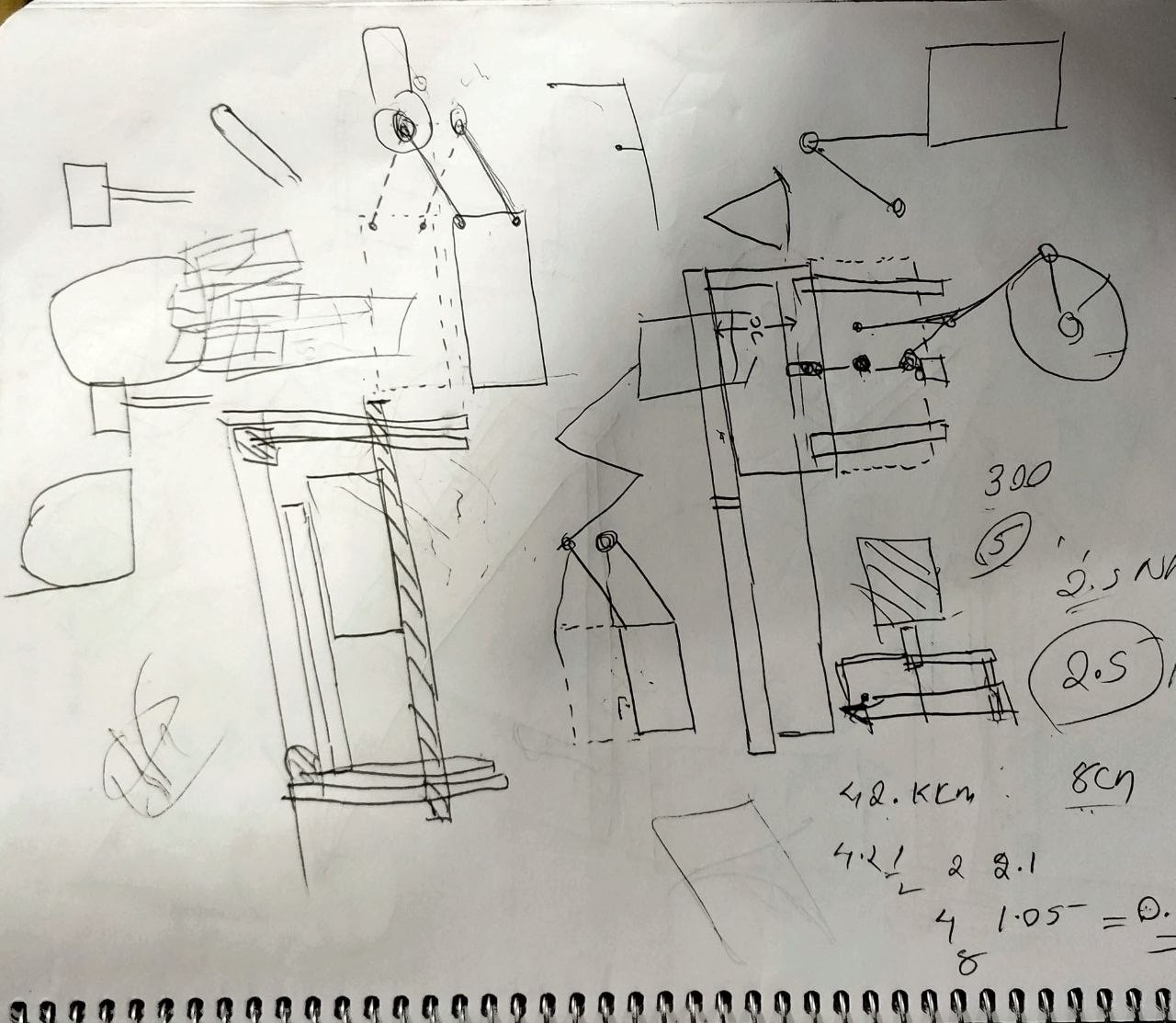
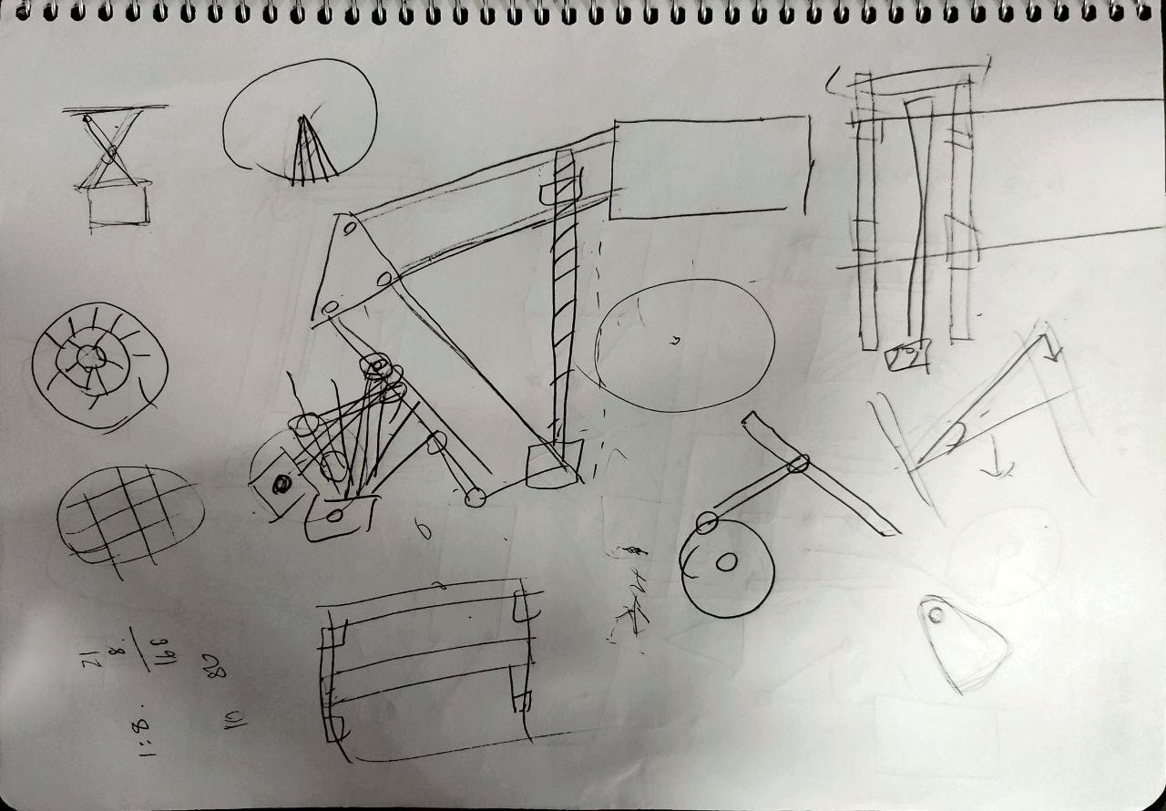
After contemplating and discussing with Jogin, our instructor, and my teammates, I chose to use lead screw for the linear cutting movement. From the below images you could see how far we have taken the design mechanisms 😪.
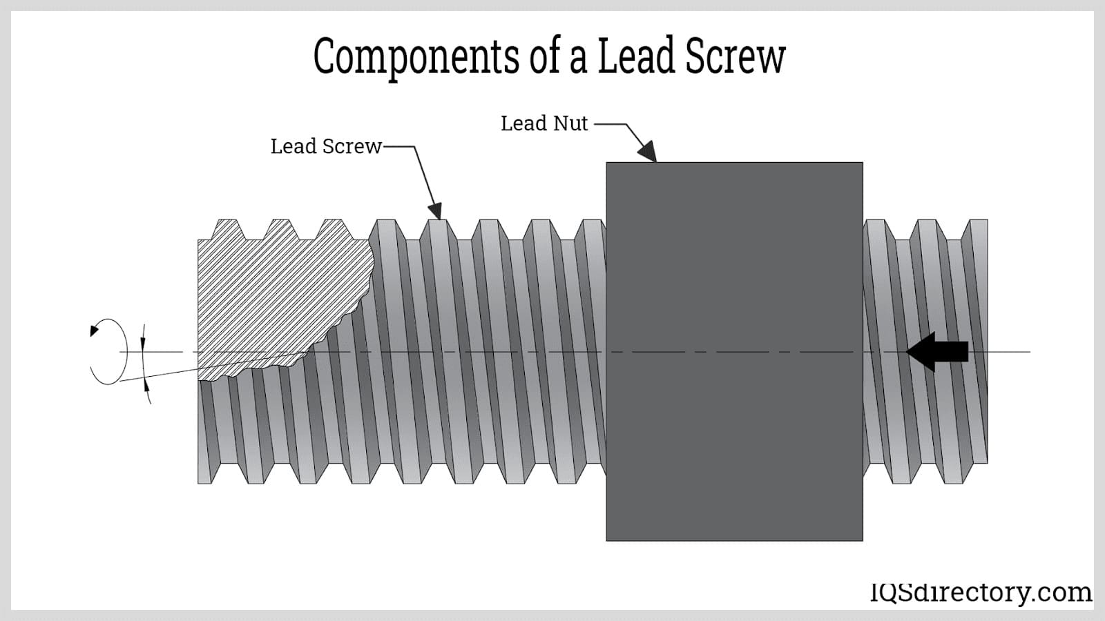
Lead Screw
Lead screw is a mechanical linear actuator that converts rotational motion into linear motion.
Components of Lead Screw
- Screw Shaft: The screw shaft is a cylindrical rod that has a single or series of grooves running helically around its length.
- Thread: The thread is the structure responsible for converting rotational motion into linear motion as the screw shaft and the nut slide with each other.
- Nut: The lead screw nut is a cylindrical section that has an internal thread that matches the external thread of the screw shaft.
Thread Starts
The number of starts refers to the number of independent threads running around the length of the thread. The lead of a screw is determined by multiplying the number of independent threads by the pitch.
Lead: The lead is the linear distance traveled by the screw shaft or nut along its axis in one complete revolution. As the lead increases, the linear speed also increases, but the load capacity of the lead screw decreases.
Pitch: The pitch is the axial distance between two adjacent threads measured parallel to the axis. It is equivalent to 1/number of threads per inch.
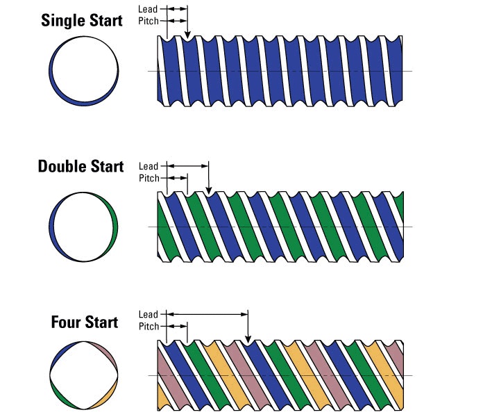
A single-start lead screw has a lead that is equivalent to its pitch. Multiple-start lead screws are used when higher speeds and higher load capacities are desired. The higher the number of starts, the longer the linear distance traveled for a single rotation. In double start lead screws, for example, the lead is equivalent to twice its pitch, which means that the axial distance covered by one rotation is two-pitch units, whereas, for four start lead screws, the axial distance covered by one rotation is four-pitch units.
For our case, I'm using four start lead screw as the aim of the mechanism is to cover the desired length in minimum time.
Design 2
For the lead screw mechanism, I designed a system where there is a blade module which can be mounted on to the lead screw tower with the help of dovetails.
Here, there were multiple problems faced.
- The module altogether looks bulky.
- The height of the blade has to be larger than the height of the cake or else, the top portion connecting the blade to the module may touch the cake, thereby, ruining the cut.
- Unnecessary distance between the tower and the blade.
I conveyed the issues with my instructor and he suggested I try a more sleek design by placing knife parallel to the lead screw tower which will eradicate all the issues I have faced during the previous design.
Design 3 (which made it to its final destination🥳)
Designing the parts were much more simpler than before. My instructor, Jogin, helped through the process to make the design more sleek and minimal.
Components incorporated in the design
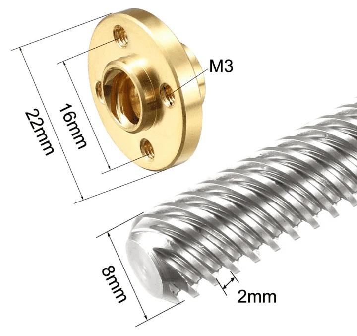
- Lead Screw: 8mm lead screw with 4 threads with a 2 mm pitch which yields 8mm of linear travel of lead screw nut for each rotation of lead screw.
- Linear Rods: 2 linear rods of 8mm diameter.
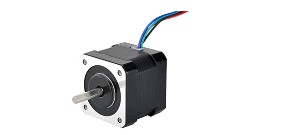
- NEMA 17 Stepper Motor: NEMA 17 has 1.8 degree step angle which translates to 200 steps per revolution with most operating efficiently in the range of 2 to 12 volts.
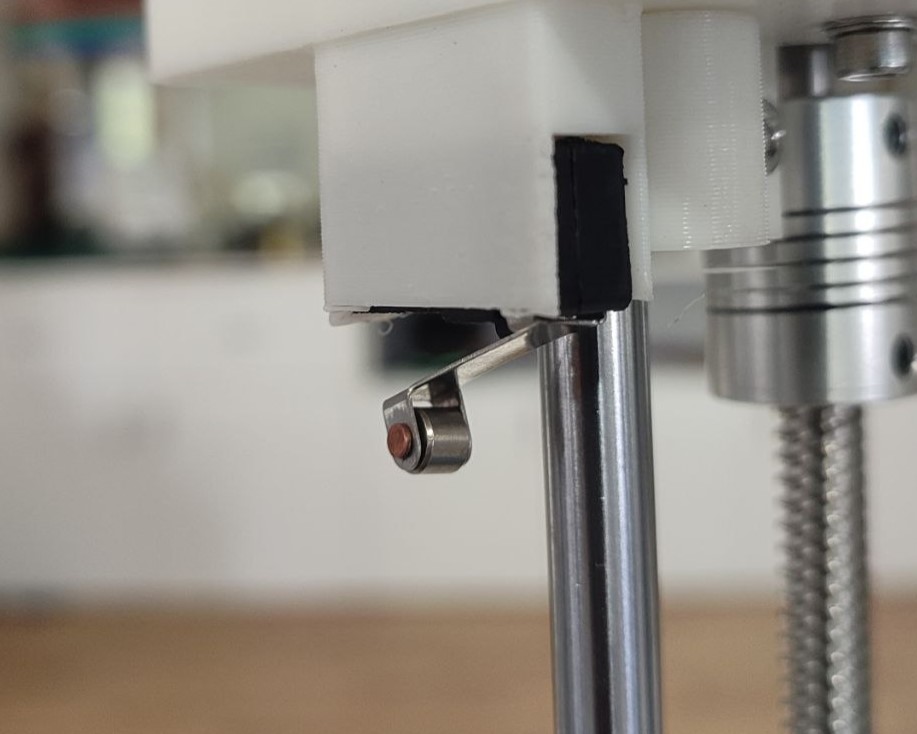
- Limit Switch: Provided at the top position so that the motor stops running as the module touches the switch indicating the top limit of the traverse.
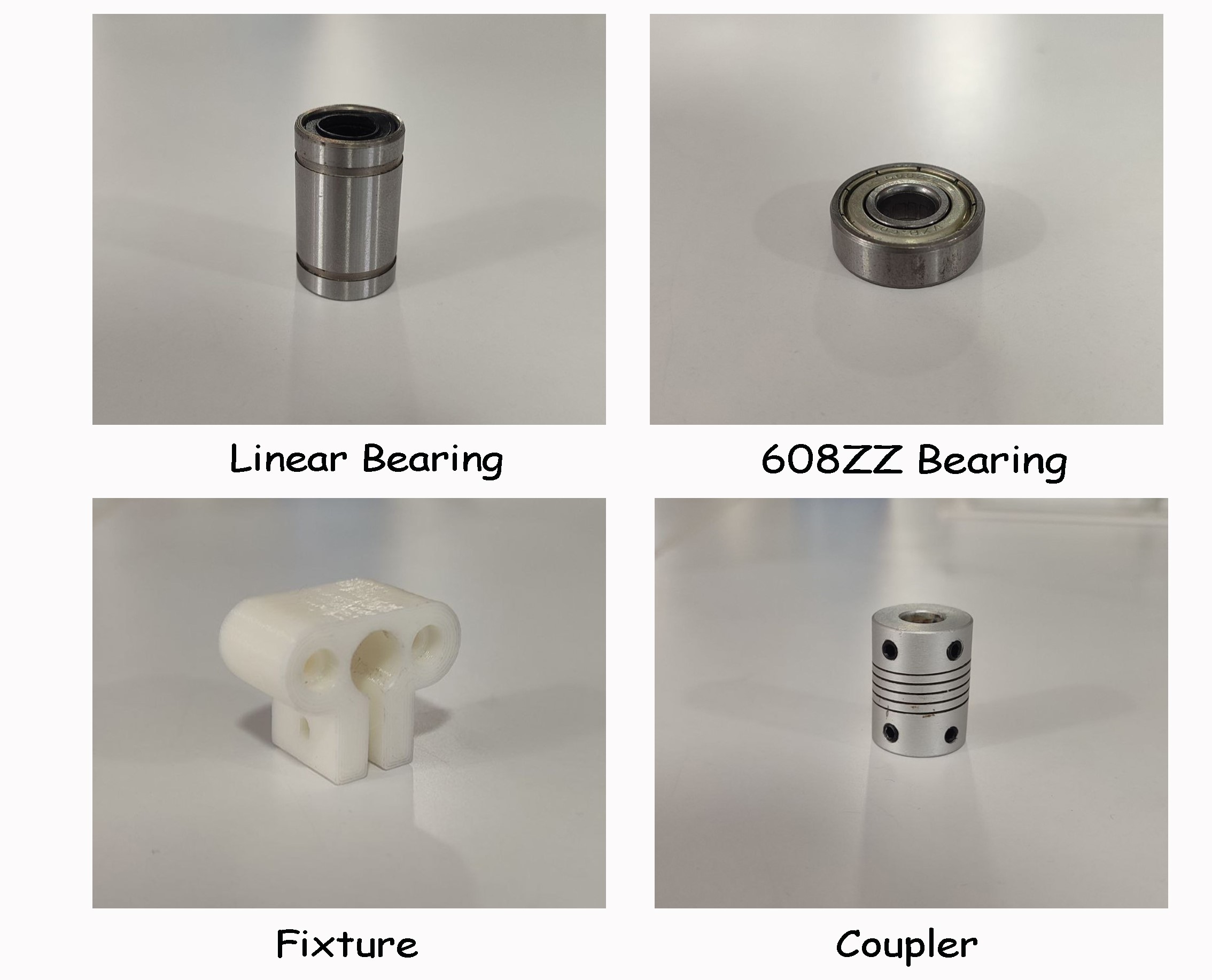
- Linear Bearing: 4 linear bearings (2 at each side) inside the blade module for the smooth movement of module through linear rods.
- Coupler: 5mm to 8mm flexible coupler to connect the motor shaft to the lead screw.
- Fixture: Designed and 3D printed fixture to hold the linear rods tight at to fix it to the base and top mount.
- Bearing: 608ZZ bearing to hold the lead screw as well as to ease the rotational motion of lead screw at the base.
- M3 and M4 screws and nuts: Throughout the designing, we have chosen to use only M3 and M4 screws for joints. Length of the screws were chosen as per the design.
Once designing was completed, I defined the joints to see if its working all good.
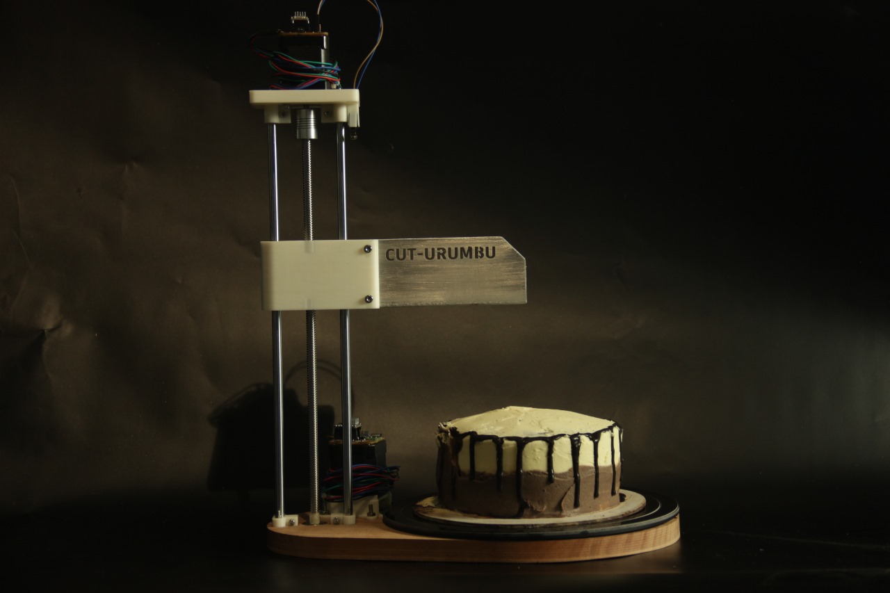
Here's the rendered image.
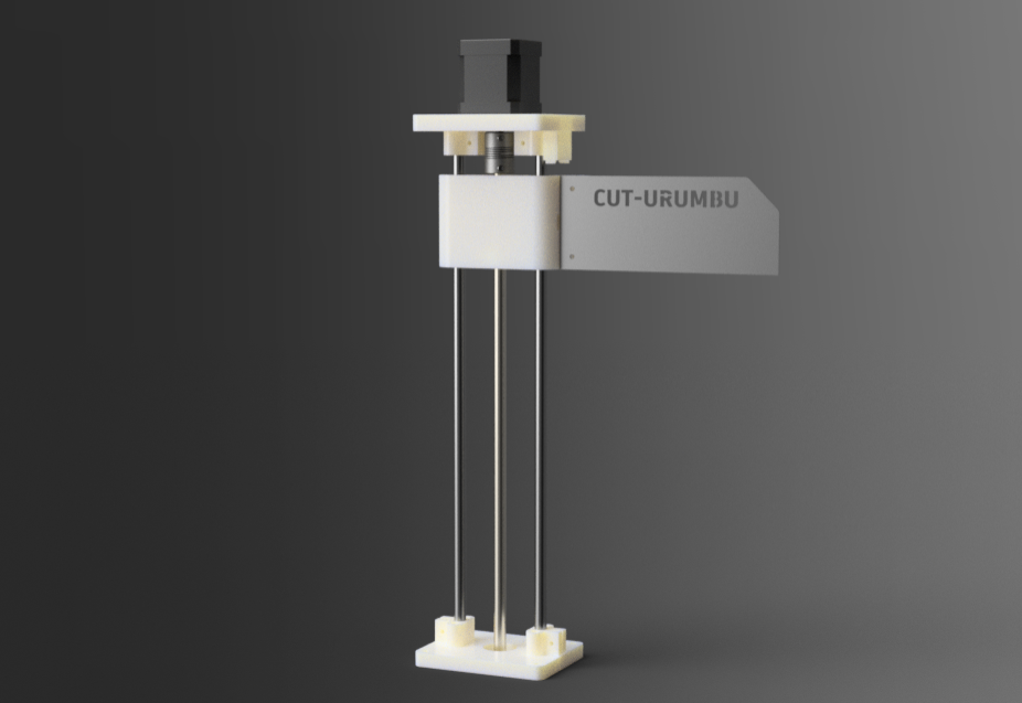
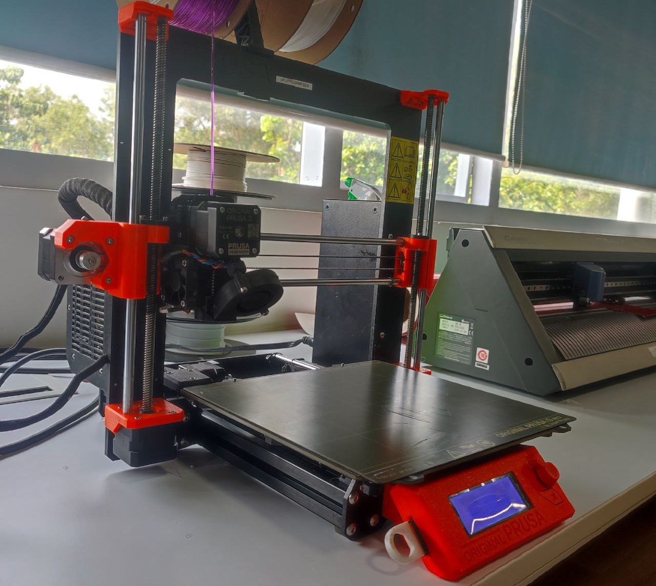
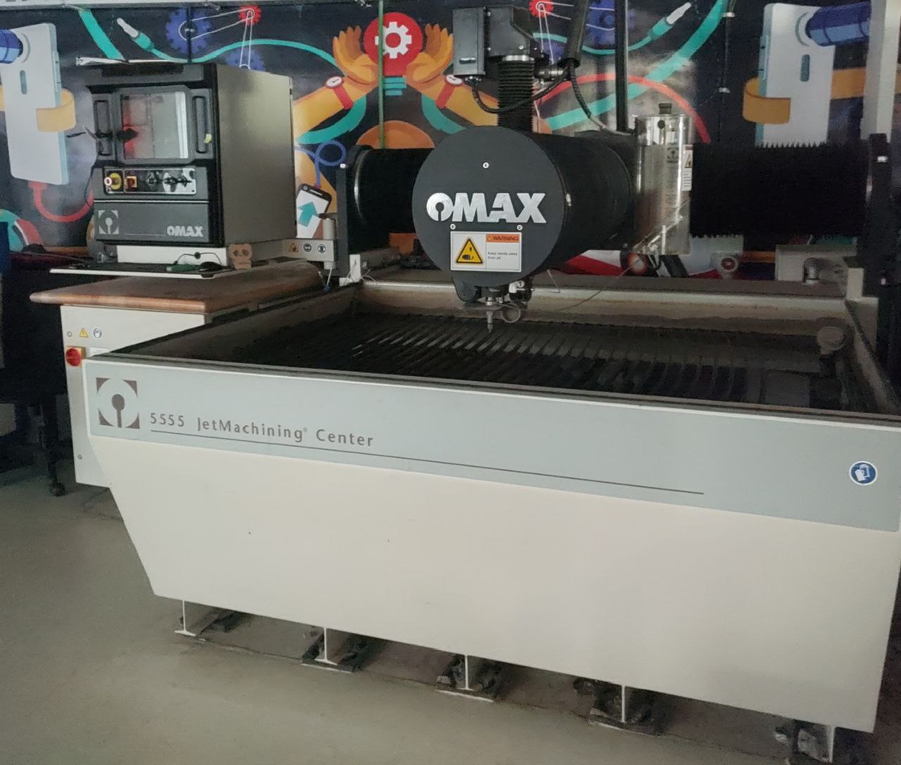
All the designed components were made to be 3D printed and the name "CUT-URUMBU" on the blade was cut using Water Jet. Before 3D printing all together, I did some sample printing for the fixture and the limit switch holder to see if it fits the components.
We used Prusa MK3 for 3D printing and OMAX 5555 Abrasive Water Jet for cutting the blade.
Assembly
The assembly was done as a team. Once completed, it was handed over to Thej for testing the codes. Refer Thej's documentation for electronics part of the project.
Working Video
Visit the page for more details of the machine.
Download Files
• Lead Screw Mechanism Design File