3D Printing & Scanning
Objectives for Week 5
- Design and 3D print an object that could not be made subtractively (small, few cm3)
- 3D scan an object (and optionally print it)
- Group Assignment: Test the design rules for the 3D Printers.
Group Assignment
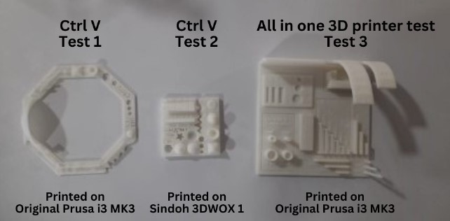
The group assignment for this week was to characterize the design rules for the 3D Printers available at our Fablab. We attempted to print 3 test pieces in Prusa i3 MK3 and Sindoh 3DWOX1. Here's the result:
For more detailed explanation, click on the link below.
Group Assignment-Week 53D Printing
3D Printing or Additive Manufacturing is a process of creating a physical object from a digital file. It can be done by different processes in which the material is deposited, joined and solidifies under computer control, with the material being added layer-by-layer. It has many advantages including:
- Quick and Cost-effective
- Offers design freedom
- Vast material choices
- Different types of processes according to requirement
- Durable
- Easily accessible
Types of 3D Printing Methods
Some of the different types of 3D Printing methods are:
• Vat Polymerization
Vat polymerization, also known as stereolithography (SLA), is an additive manufacturing process that uses a vat of liquid resin and a light source to create 3D objects layer by layer.
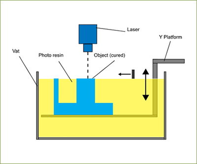
Working Principle of Vat Polymerization (source)
• Material Extrusion
Material extrusion 3D printing, also known as Fused Deposition Modeling (FDM), is a popular and versatile additive manufacturing process that builds objects layer by layer using a continuous filament of thermoplastic material.
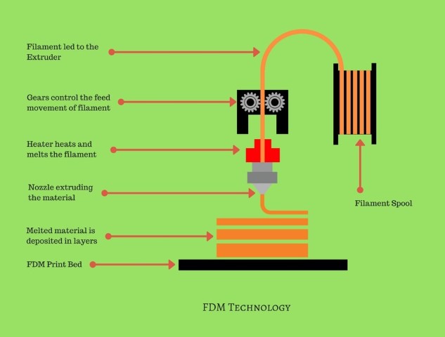
Working Principle of FDM (source)
• Powder Bed Fusion
Powder bed fusion (PBF) is a fascinating and powerful 3D printing technology that builds objects layer by layer using powdered materials.
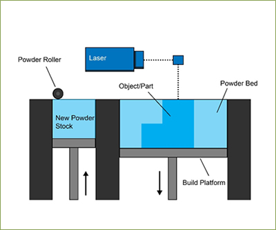
Working Principle of Powder Bed Fusion (source)
• Material Jetting
Material jetting, also known as PolyJet or MultiJet Printing (MJP), is an additive manufacturing technology that creates objects layer-by-layer by jetting droplets of liquid photopolymer material.
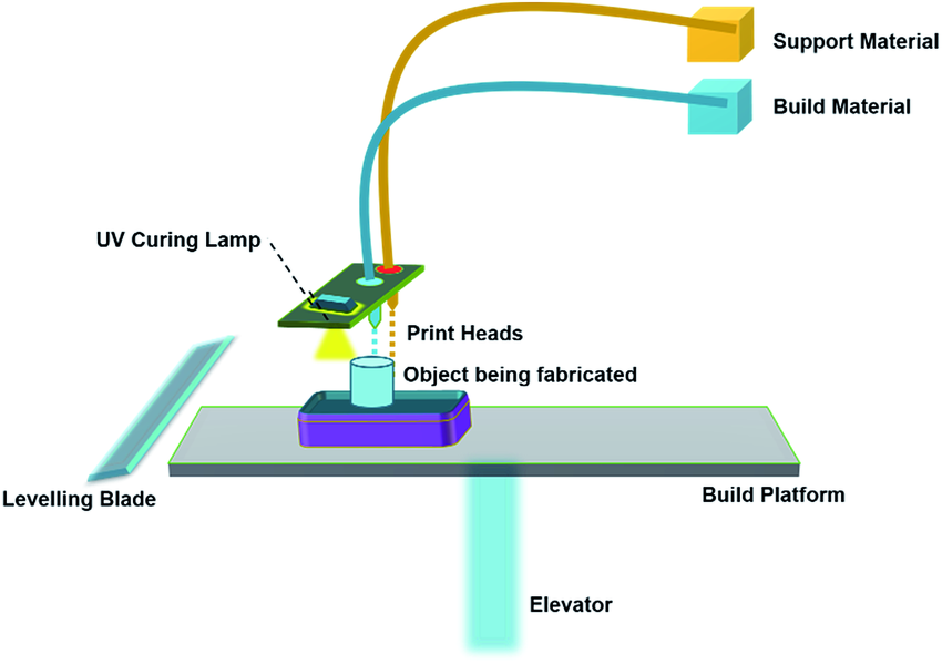
Working Principle of Material Jetting (source)
• Binder Jetting
Binder jetting is a versatile 3D printing technology that uses a combination of powdered materials and a binding agent to create objects layer by layer. It's similar to inkjet printing, but instead of ink on paper, you're building a solid object with various materials like metal, plastic, sand, or even ceramics.
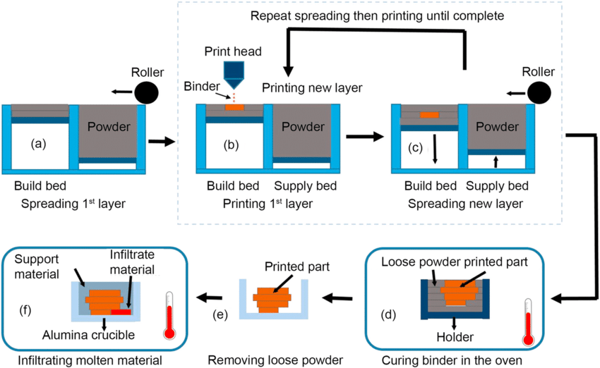
Working Principle of Binder Jetting (source)
• Direct Energy Deposition
Direct Energy Deposition (DED) is a fascinating and versatile additive manufacturing technology that utilizes a focused energy source to melt and fuse material onto a surface, building objects layer by layer.
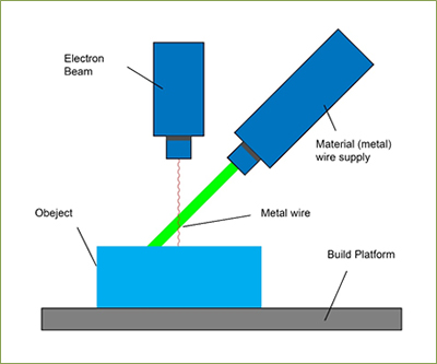
Working Principle of Direct Energy Deposition (source)
• Sheet Lamination
Sheet lamination, also known as Laminated Object Manufacturing (LOM), is an additive manufacturing (3D printing) technology that creates objects layer by layer using thin sheets of material. Unlike other methods that melt or fuse materials, sheet lamination relies on bonding sheets together to build the desired shape.
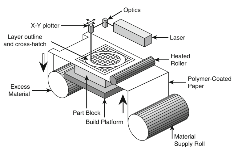
Working Principle of Sheet Lamination (source)
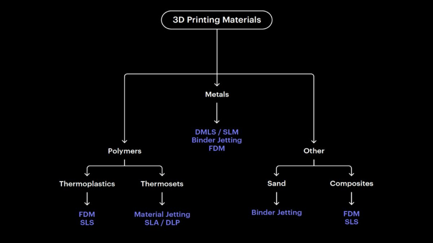
Image sourced from Hubs
Follow the link to know more about 3D Printing: https://www.hubs.com/guides/3d-printing/
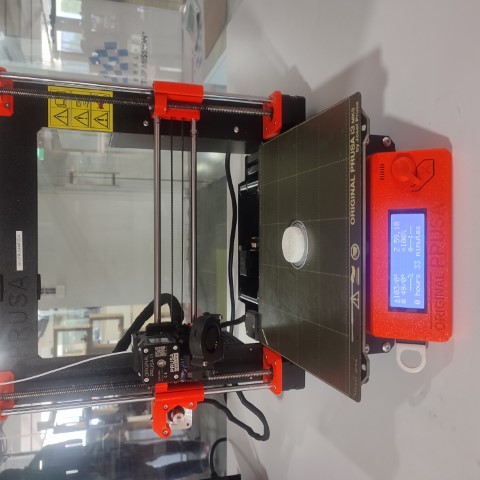
Prusa i3 MK3
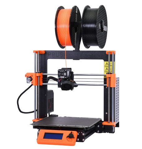
The Prusa i3 is a Fused Deposition Modeling 3D Printer we have here at our Fablab.
Specifications of Prusa i3 MK3:
- Build Volume: 250x210x210mm
- Nozzle: 0.4mm (default), 0.6mm
- Layer Resolution High : 50 microns
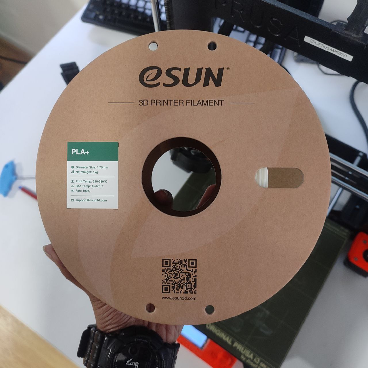
Here are some of the materials that can be used for FDM 3D Printing:
- Acrylonitrile Butadienen Styrene (ABS)
- Polylactic Acid (PLA)
- Polyethylene Terephthalate Glycol (PETG)
- Nylon
- Polycarbonate (PC)
- Thermoplastic Polyurethane (TPU)
- Woodfill (Wood fibers + PLA)
Of all the materials, PLA is the commonly used material. It is a biodegradable and biocompatible material that is easy to print with and produces smooth finishes. I used the same material for my work.
Parameter values set for PLA+ in Prusa:
- Nozzle Temperature: 215°C
- Bed Temperature: 60°C
Design 1 - Ring
The assignment for this week is to 3D print a model that cannot be made by subtractive manufacturing.
First, I tried designing a ring for me. I used Fusion 360 for creating the model. It was not exactly a part of the assignment, I just wanted to see how it turns out and I wanted to be familiar with the steps for 3D Printing. 😌
Once desigining completed, next step is to open it in a Slicer software. For that, I saved the file in .stl format as slicer can only read .stl and .obj formats.
PrusaSlicer-2.7.1
Slicing is a crucial step in the 3D printing process, acting as the bridge between your digital 3D model and the physical object the printer will create. It invloves dividing the 3D model into thin horizontal slice. Each slice represents a cross-section of the object at a specific point in its height. Slicer also provides infill and support structures required for the model.
The final product of slicing is a G-code file, which contains all the instructions for the printer to execute. This file tells the printer exactly where to move, how much and when to extrude material, and other relevant information for each layer.
There are many options of Slicer to choose from. Our instructor, Mufeed, suggested we use PrusaSlicer-2.7.1. Download the slicer from here.
I dragged and dropped the file into the Slicer.
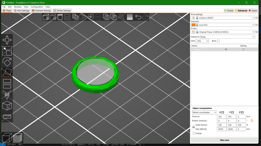
The settings for the filaments and print settings were preloaded and I used the same default values for this model.
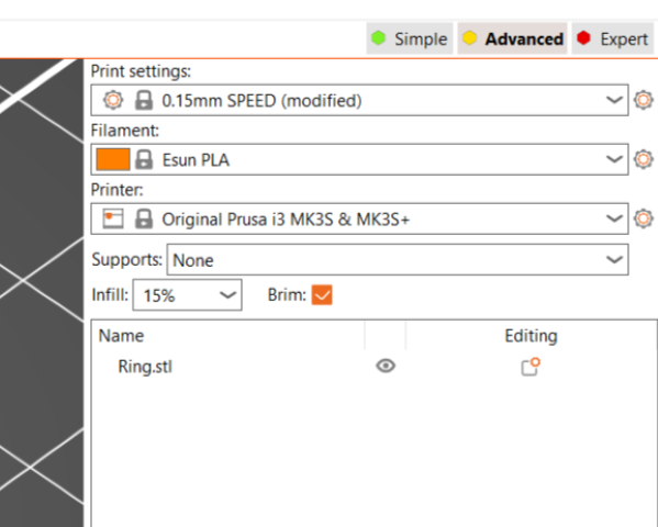
Later, I provided Brim and clicked on Slice now to generate the sliced model.
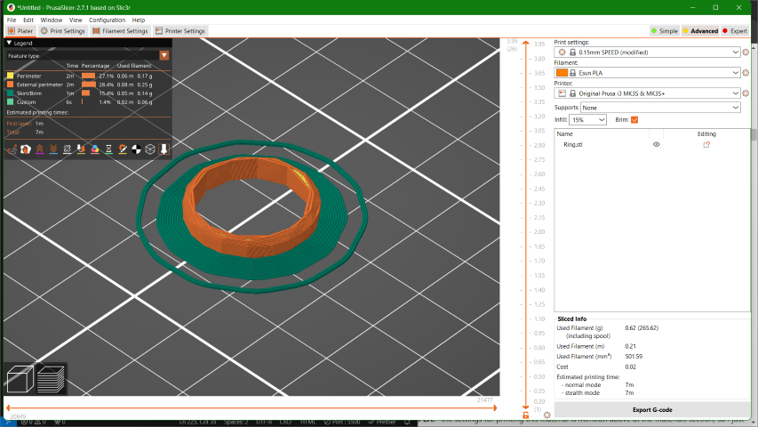
Once completed, you will be able to see the overall time taken for printing and the amount of material that will be used. This ring only takes about 7 minutes to print as shown by the slicer. As I was satisfied with the values, I clicked on Export G-code to extract the g-code gile.
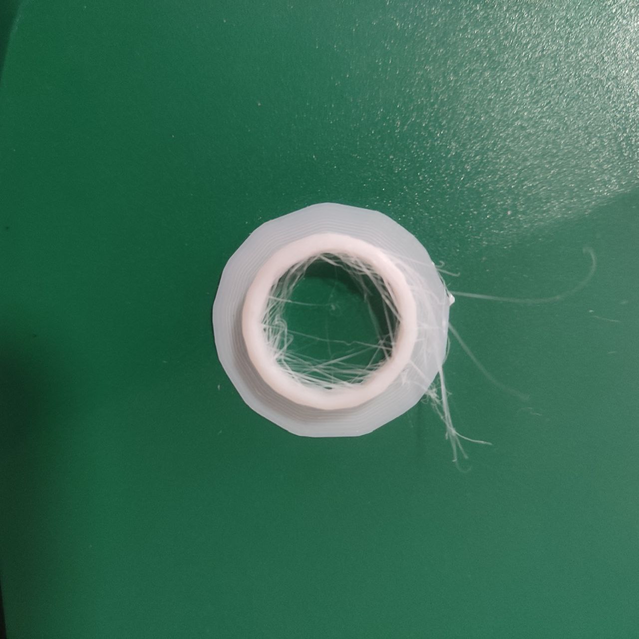
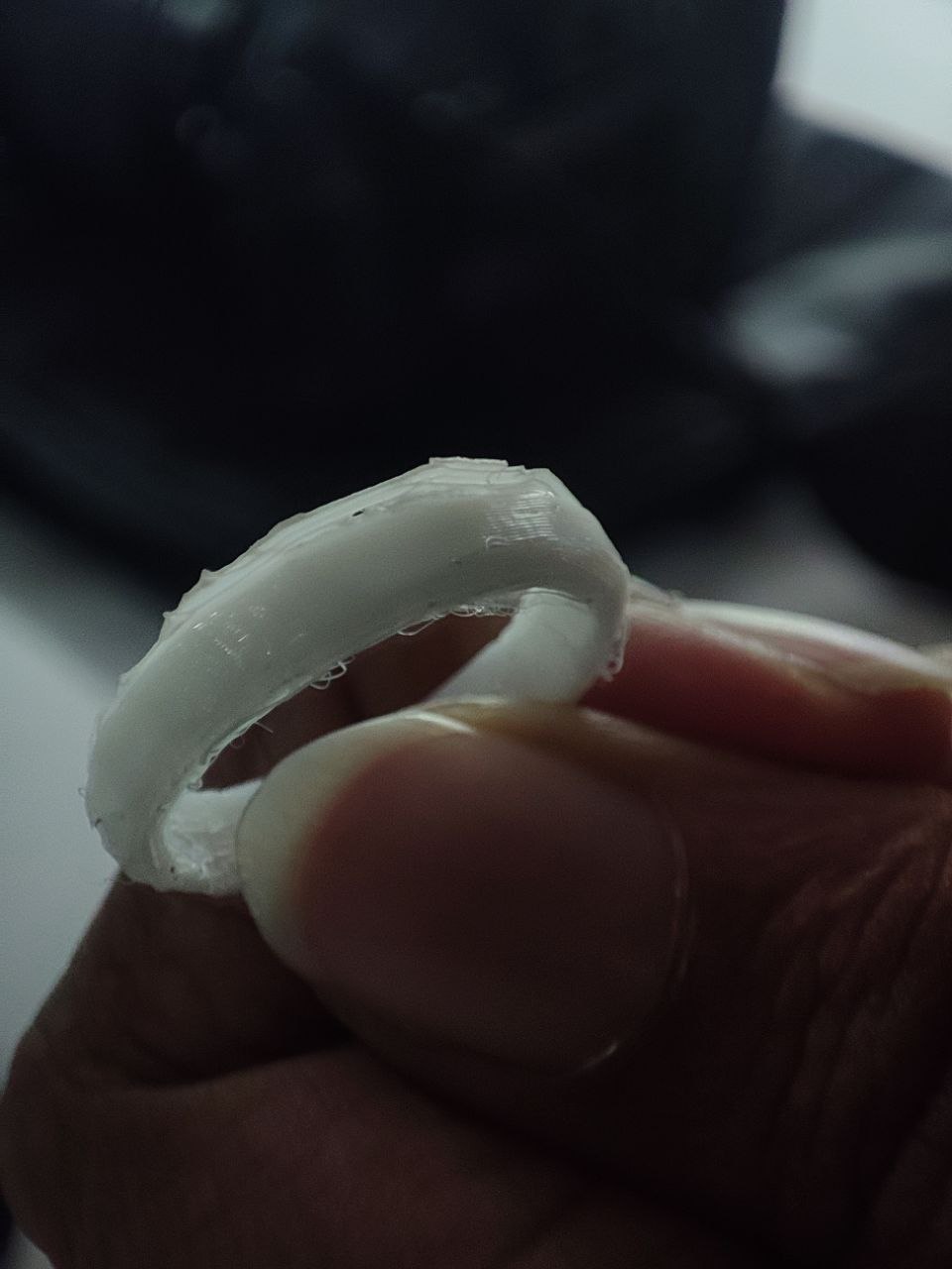
Result
The print was completed but the geometric patterns on the ring was not clear as the scale was really small to give such details.
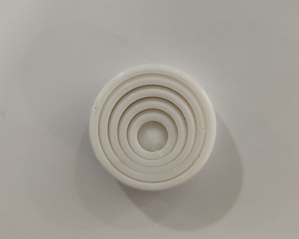
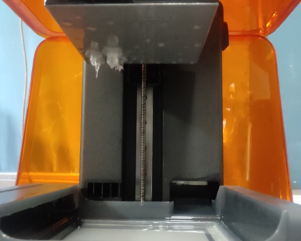
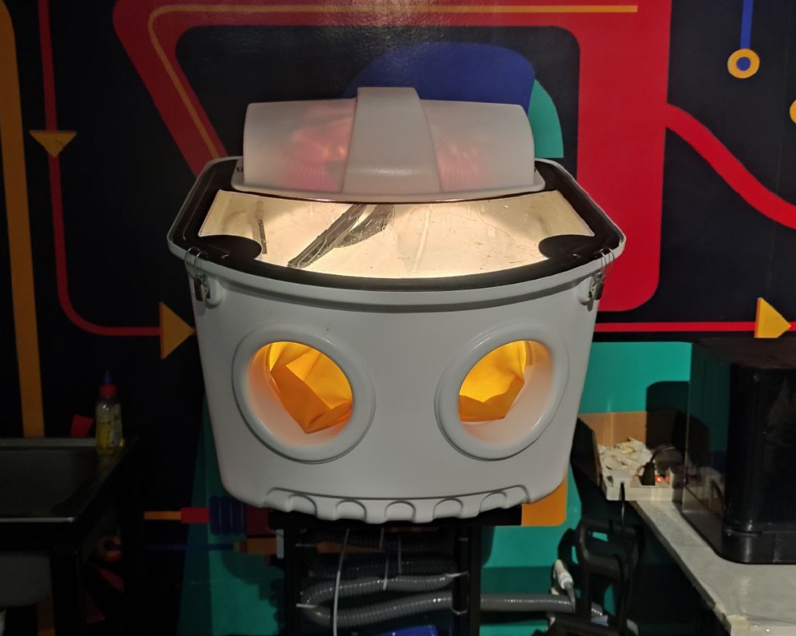
Design 2 - Gyroscopic Rings
For my assignment, I planned to create a Gyroscopic rings. I love fidget toys, so, I thought why not take this opportunity to 3D print one. And also the gyroscopic rings cannot be made subtractively because it is a print-in-place model. Designing the rings were really easy. The only moderately tiring task was sketching the circles and dimensioning the size and space between each circles.
Next, I imported the .stl file in the Slicer. I changed the print settings to 0.30mm DRAFT and then clicked on Slice now.
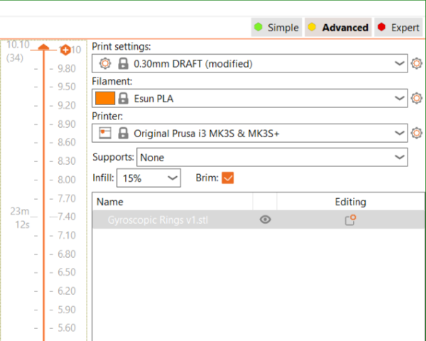
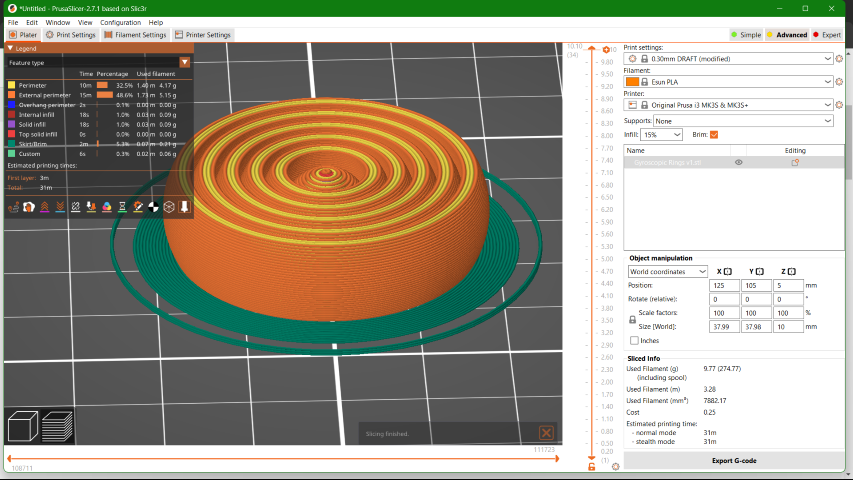
Then, I clicked on Export G-code once all the values were satisfying.
Result
Form 3+
-min.png)
The Form 3+ is an advanced desktop Stereolithography (SLA) 3D printer produced by Formlabs, which is well-regarded for its precision and reliability. We can produce functional, high-quality prototypes and end-use parts with the Form 3+. The Form 3+ offers reliable print quality and accuracy, easy setup and maintenance, and a wide range of high-performance materials.
Build Volume: 5.7×5.7×7.6 in
Features:
- LFS (Low Force Stereolithography) Technology: The Form 3+ utilizes Formlabs' proprietary LFS technology, an advanced form of SLA that uses a flexible tank and linear illumination to achieve fine detail and smooth surface finishes.
- Increased Printing Speed: The Form 3+ boasts improved printing speeds, thanks to its more powerful laser and optimized print processes. This results in faster turnaround times for projects without compromising the quality of the print.
- High Precision and Accuracy: With its advanced laser system and high-quality optics, the Form 3+ can produce parts with incredible detail and accuracy, making it suitable for applications that require tight tolerances, such as dental, jewelry, and prototyping for engineering.
- Wide Range of Materials: Formlabs offers a comprehensive library of resin materials compatible with the Form 3+, including standard, engineering, dental, and castable resins. This versatility makes the printer suitable for a broad array of applications, from functional prototyping to end-use parts production.
Preform
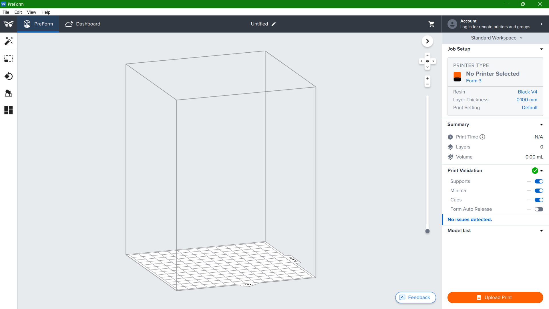
PreForm is the proprietary software developed by Formlabs, designed to prepare 3D models for printing on Formlabs' range of stereolithography (SLA) and selective laser sintering (SLS) printers, such as the Form 2, Form 3, Form 3+, Form 3L, and Fuse 1. It serves as a bridge between digital 3D models and physical objects, offering users an intuitive and powerful tool for print preparation.
Features:
- One-Click Print: PreForm analyzes the geometry of the 3D model and automatically suggests an orientation, supports, and layout that would result in a successful print, making the software accessible to users of all experience levels.
- Manual Controls: For users who prefer more control over their prints, PreForm offers detailed manual settings for support structure customization, model orientation, and layout adjustments. This level of control is crucial for optimizing print success for complex or highly detailed models.
- Advanced Support Structures: The software generates support structures that are optimized for SLA printing, ensuring that models with overhangs or delicate features can be printed successfully. These supports are designed to be easily removable and to minimize post-processing time.
- Detailed Simulation: PreForm includes a simulation mode that predicts the layer-by-layer printing process. This feature allows users to identify potential problem areas before printing begins, saving time and reducing material waste.
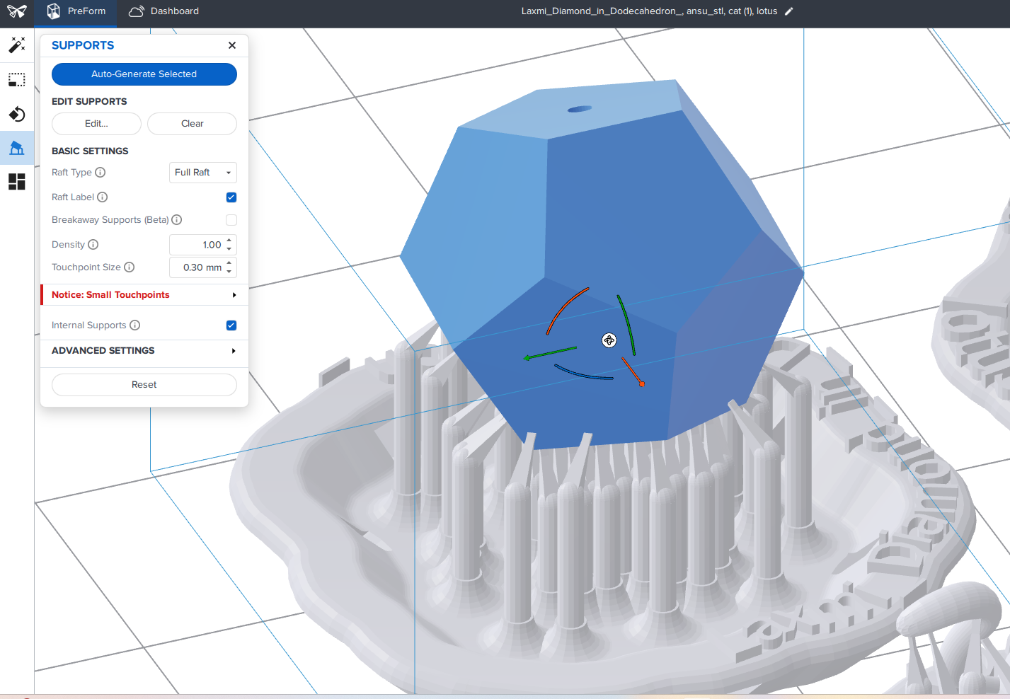
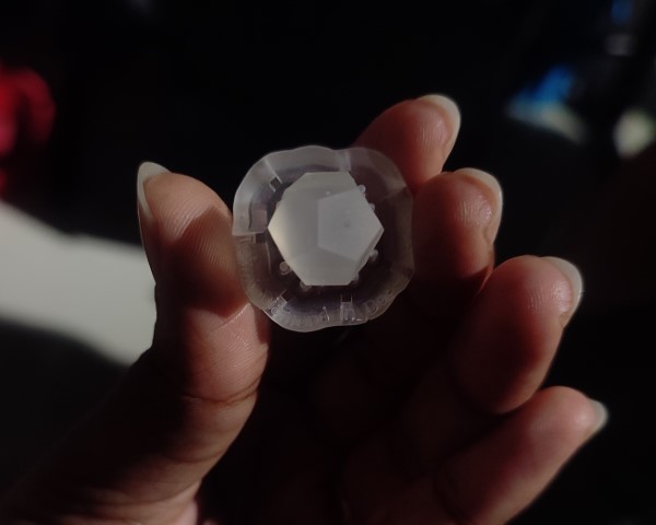
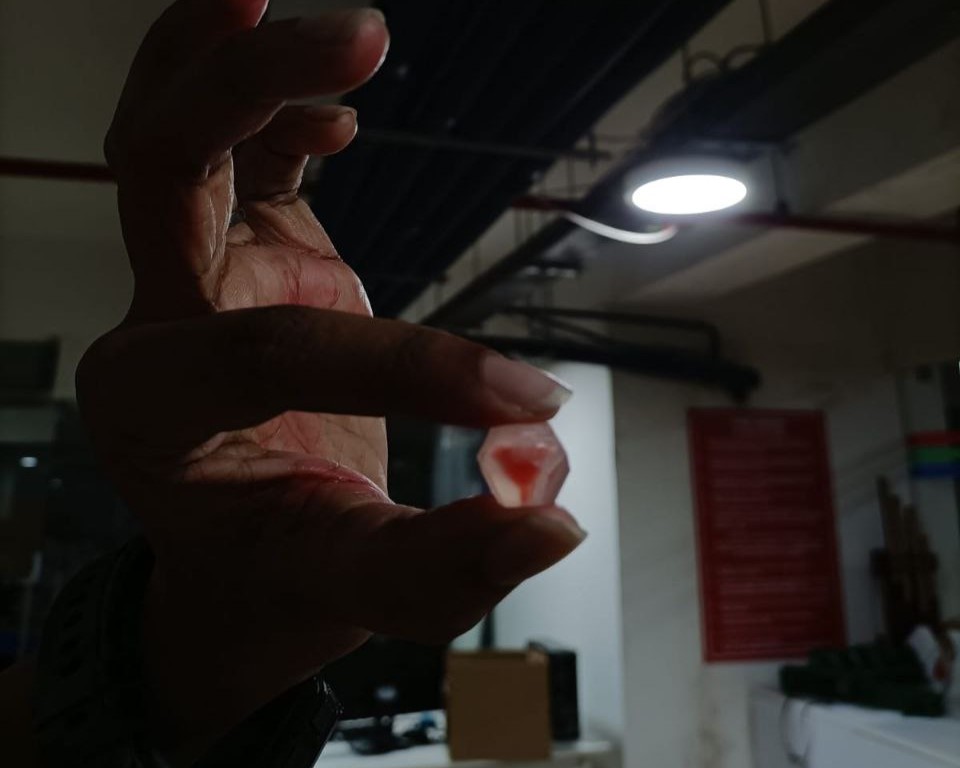
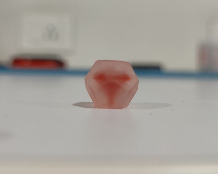
Design 3 - Diamond in Dodecahedron
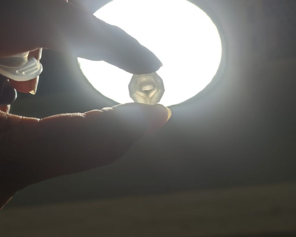
For SLA 3D Printer, I designed a diamond placed inside a dodecahedron. A 1mm hole has been also provided to drain out the resin that will be stuck inside the diamond.
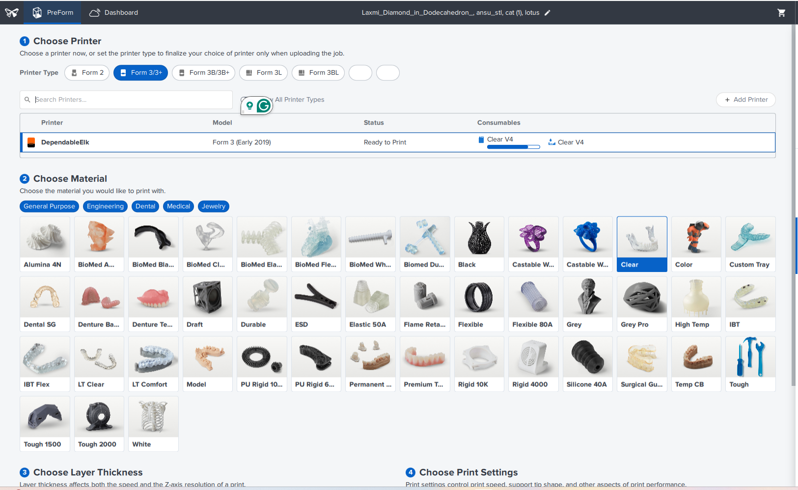
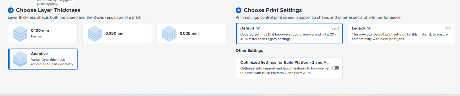
I imported the file in Preform and gave the below settings.
Post Processing Steps in SLA
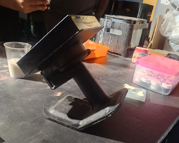
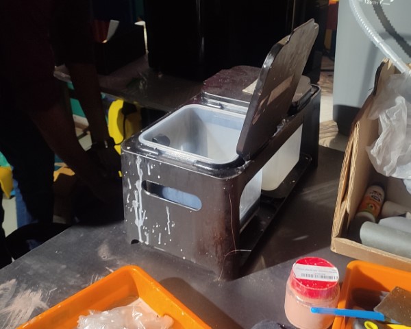
- Once the printing is completed, we removed the bed from Forms 3+. It is necessary to wear gloves before handling with the machines as the resin is toxic when it is not cured.
- We placed the bed on a stand as shown below and with the help of a pry tool we removed the models carefully from the bed.
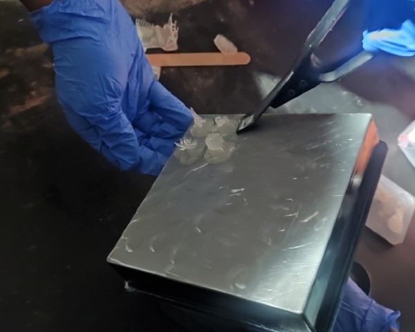
- Next step was to wash off the excess resin from the models. This process was done in two steps. First, we place the models inside an Isopropyl (IP) bath and dip them repeatedly.
- Second wash is also done using a machine that has IP Alcohol but here, the washing is done by whirling effect same as in washing machines.
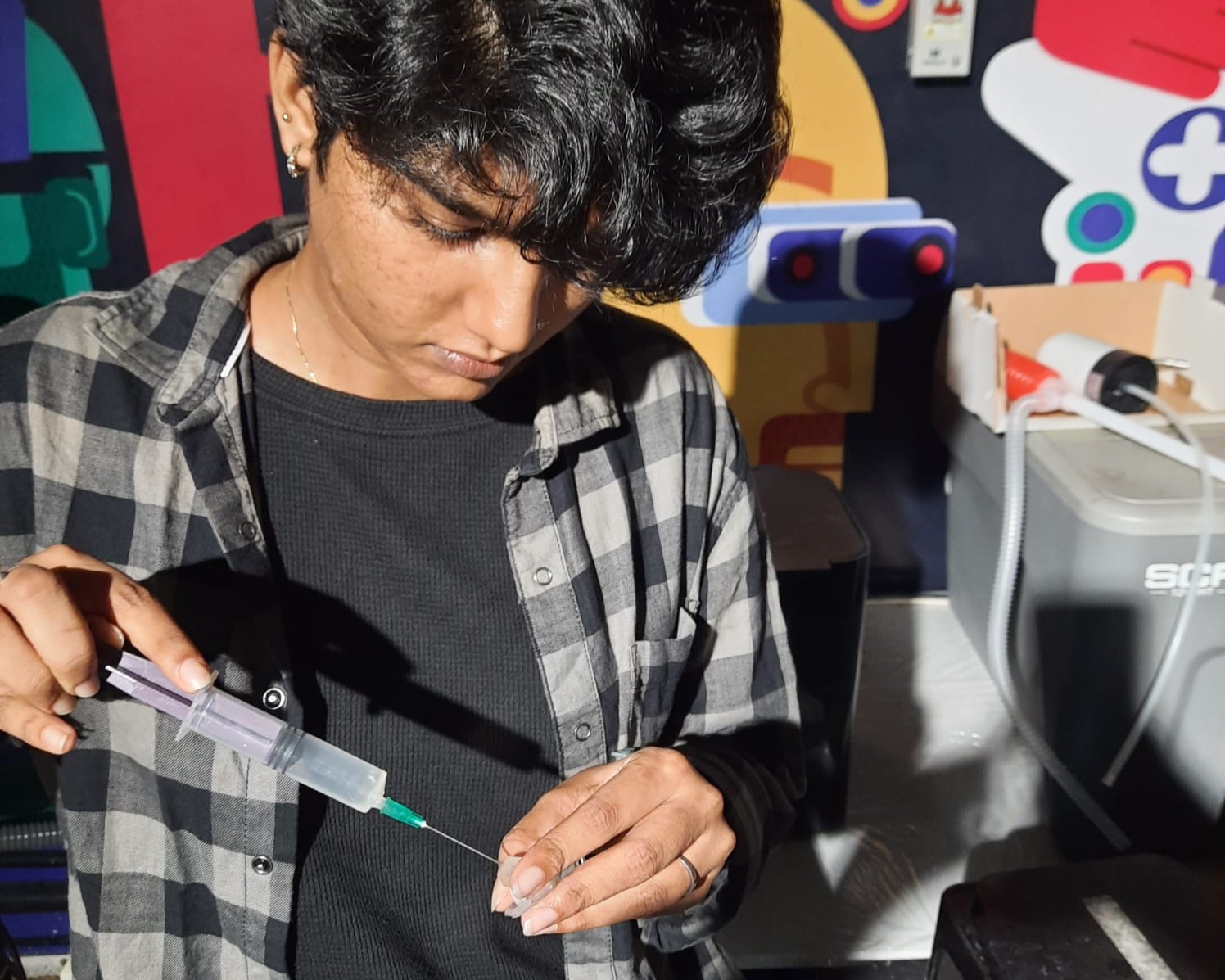
- I inspected the model under light and I was able to find bubbles inside the diamond, as the excess resin was trapped inside.
- So, first I tried using a syringe to remove the trapped resin. I did it directly in the beginning and then I pushed in some IP inside and tried diluting the resin. This way most of the resin was removed and I was able to see some part of the diamond. Still the edges were not clear.
- Next, I tried using pressurized water to clear the inside and it was successful.
- Then, I used compressed air to remove the water inside the diamond.
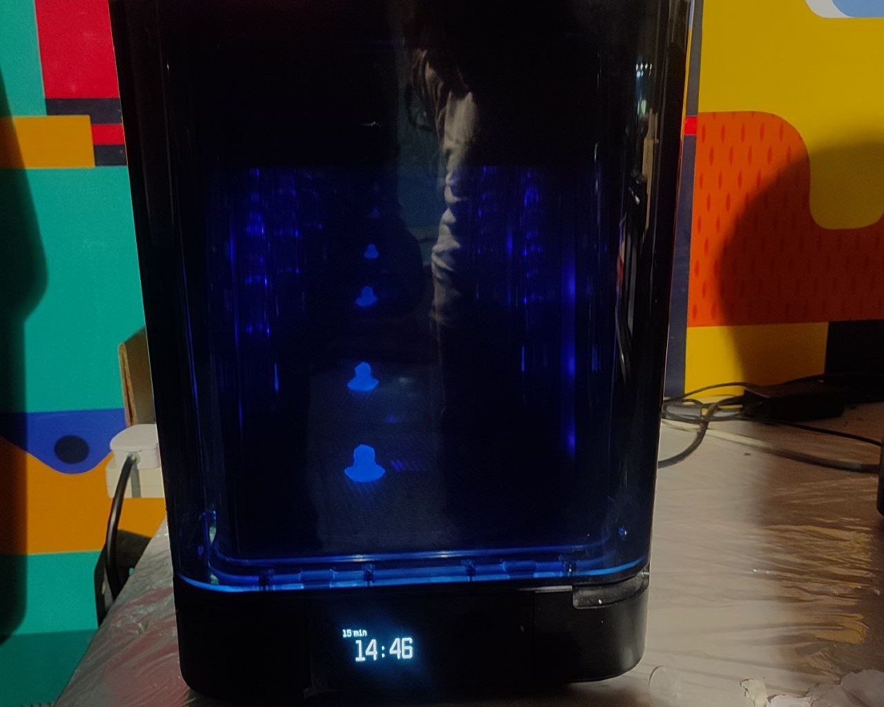
- After I was satisfied, I placed my model in the curing machine. From the documentation for Forms 3+, we identified the required temperature and time for clear resin.
- Temperature: 60°C
- Time: 15 minutes
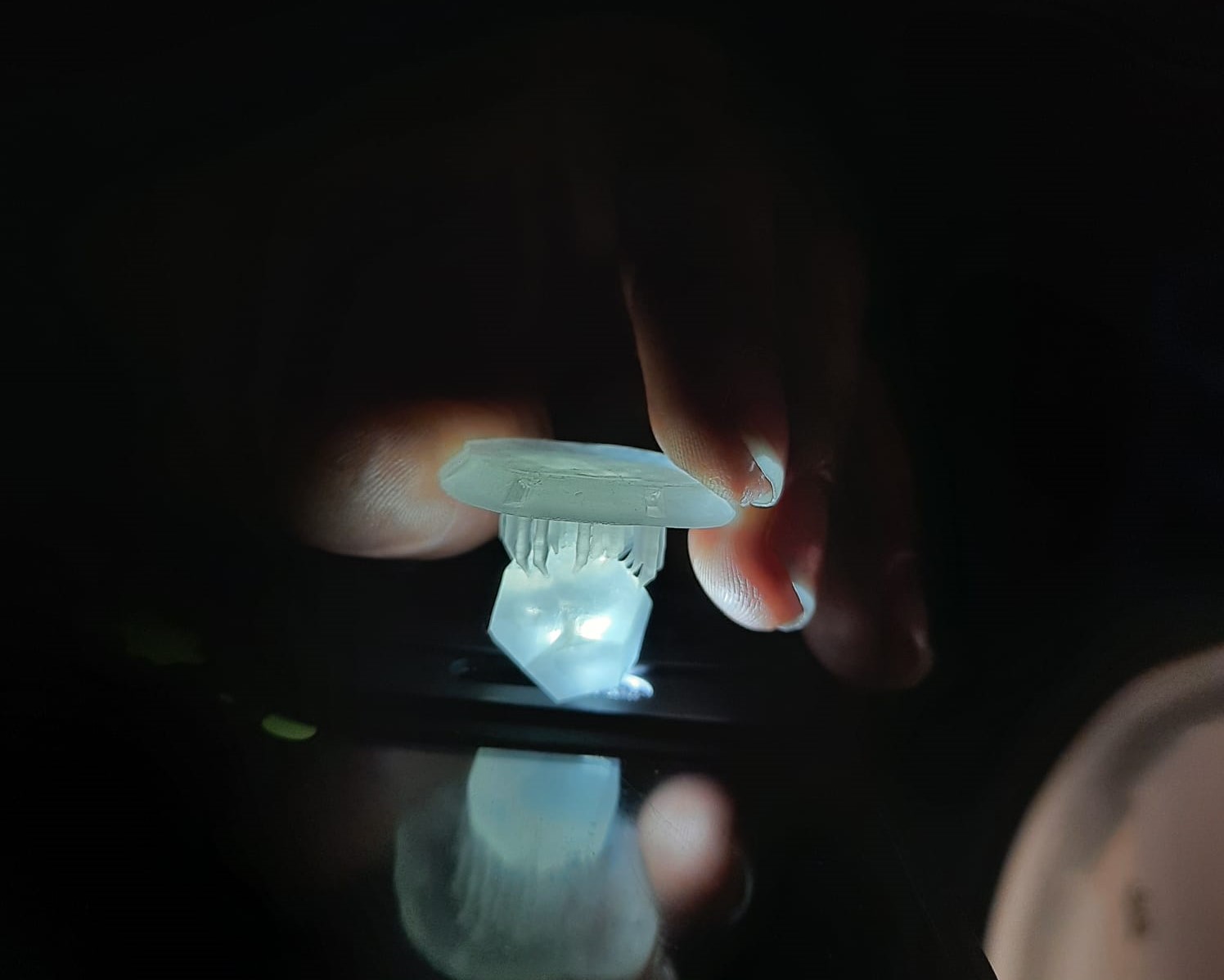
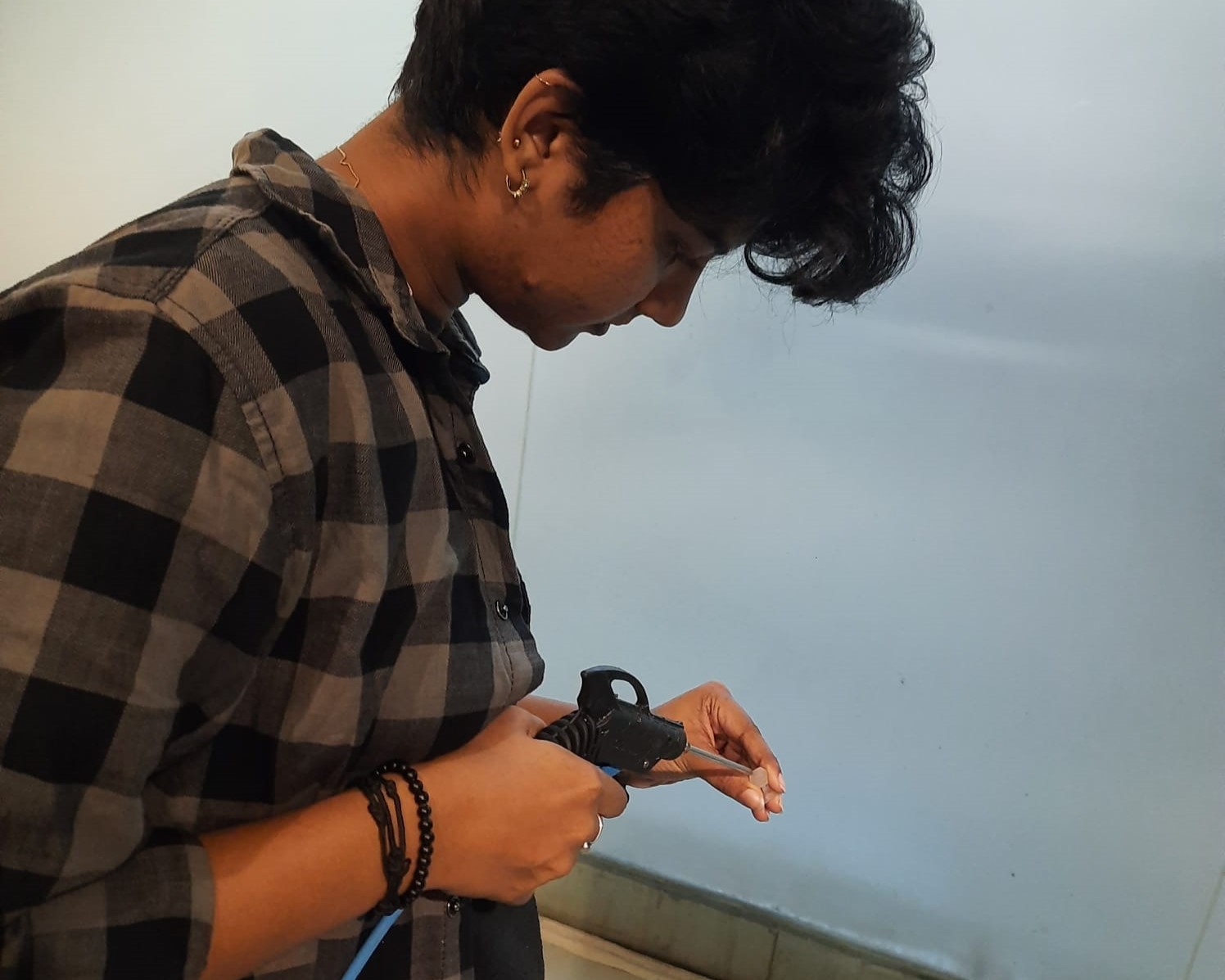
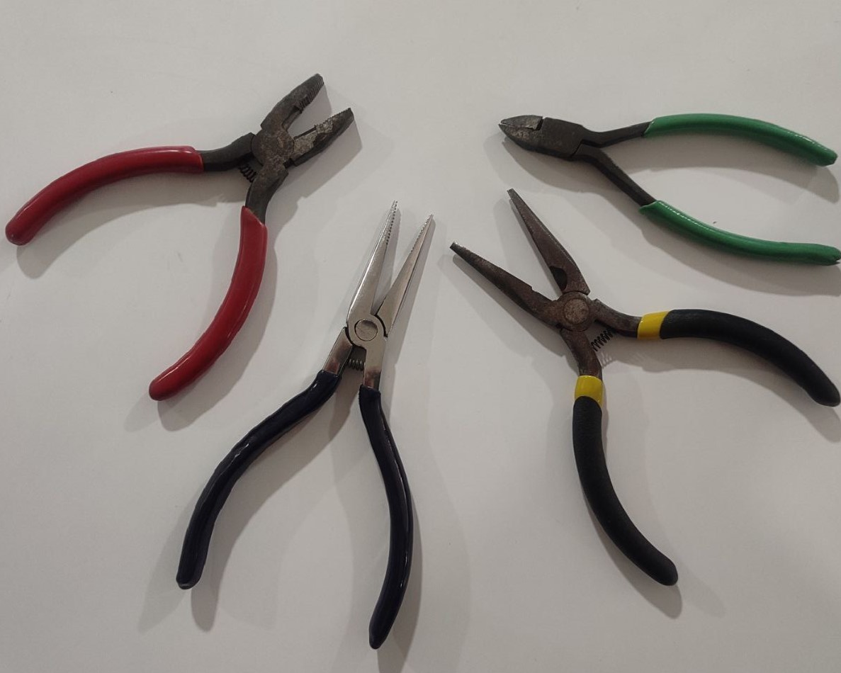
- Then, I removed the supports with the help of some tools and the 3D printed resin model was ready. I tried taking a photo but the diamond was not visible properly in the photos.
- I added coloured water inside the diamond so tht it can be more clear and here's the outcome:
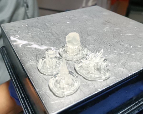
After washing
3D Scanning
3D scanning is a technology that captures the shape of a physical object or environment using specialized equipment, such as laser scanners, structured light scanners, or photogrammetry setups. This process converts the real-world data into a digital 3D model, which accurately represents the object’s size, shape, and surface textures. 3D scanning is utilized across various industries and applications, including but not limited to manufacturing, architecture, engineering, healthcare, entertainment, and cultural heritage preservation.
3D Scanning Technologies
• Laser Scanning
Uses a laser beam to capture the 3D shape of an object. This can be further divided into handheld scanners or stationary setups, suitable for different scales and precision levels.
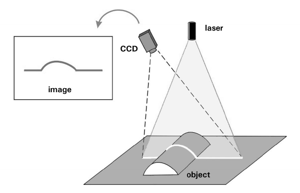
Working Principle of Laser Scanning (source)
• Structured Light Scanning
Projects a pattern of light onto the object and captures its deformation with a camera to construct the 3D shape. This method is often faster and safer for scanning living subjects than laser scanning.
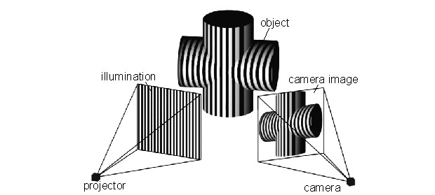
Working Principle of Structured Light Scanning (source)
• Photogrammetry
Involves taking a large number of photographs from different angles and using software to stitch these images together into a 3D model. While potentially less precise than other methods, it is highly versatile and requires minimal specialized equipment.
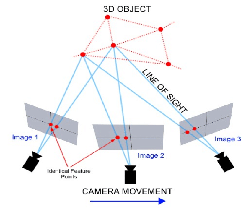
Working Principle of Photogrammetry (source)
Artec Leo 3D Scanner

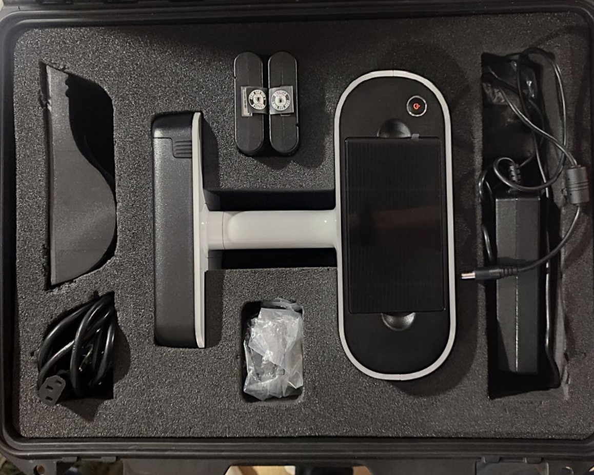
The Artec Leo is one of the most advanced handheld 3D scanners in the professional 3D scanner market, designed and manufactured by Artec 3D, a leader in 3D scanning technology. Known for its portability, ease of use, and high-quality data capture, the Leo stands out for several reasons, including its ability to streamline the 3D scanning process for a wide range of applications.
Features:
- It is a fully self-contained unit, with an onboard processor and battery.
- It features a built-in touchscreen display that shows the scanned data in real-time.
- The Leo is capable of capturing objects in high resolution and with a high degree of accuracy, making it suitable for applications that require precise measurements, such as industrial design, manufacturing, quality control, and healthcare.
- It has a wide field of view, allowing it to capture both large objects and detailed features of smaller items.
- Unlike some other 3D scanning systems, the Artec Leo can perform accurate scanning without the need for placing physical markers on the object.
- Being wireless, the Leo offers unparalleled freedom in scanning, allowing users to reach difficult or confined spaces without the encumbrance of cables.
Artec Studio 15 Professional
Artec Studio 15 Professional is a powerful software suite designed for use with Artec's 3D scanners. Artec Studio is renowned for its advanced 3D scanning and data processing capabilities.
Artec Studio 15 Professional offers a comprehensive set of features designed to simplify and enhance the 3D scanning process. Here are some of the key features and capabilities of the software:
- High-Precision Scanning: It supports high-precision scanning, making it suitable for industrial design and quality control, where detail accuracy is paramount.
- Advanced Processing Tools: The software includes advanced tools for processing 3D scans, including automatic alignment, mesh simplification, and advanced filtering options, which help in refining the scan data.
- Texture and Color Capture: Artec Studio 15 Professional supports full-color 3D scanning, capturing detailed textures alongside geometric shapes, which is particularly useful in media, arts, and heritage preservation.
- CAD Compatibility: It offers features for reverse engineering and integration with CAD software, allowing users to export scans into various formats compatible with most CAD systems. This is crucial for engineering and manufacturing processes.
- Automation Capabilities: The software can automate many tedious tasks involved in 3D scanning and processing, such as auto-alignment and auto-mesh generation, saving time and effort for users.
Scanning
Model 1
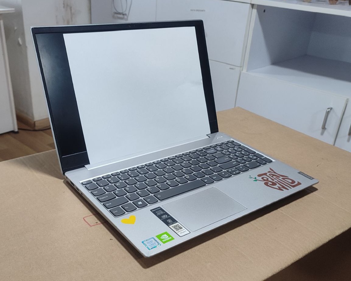
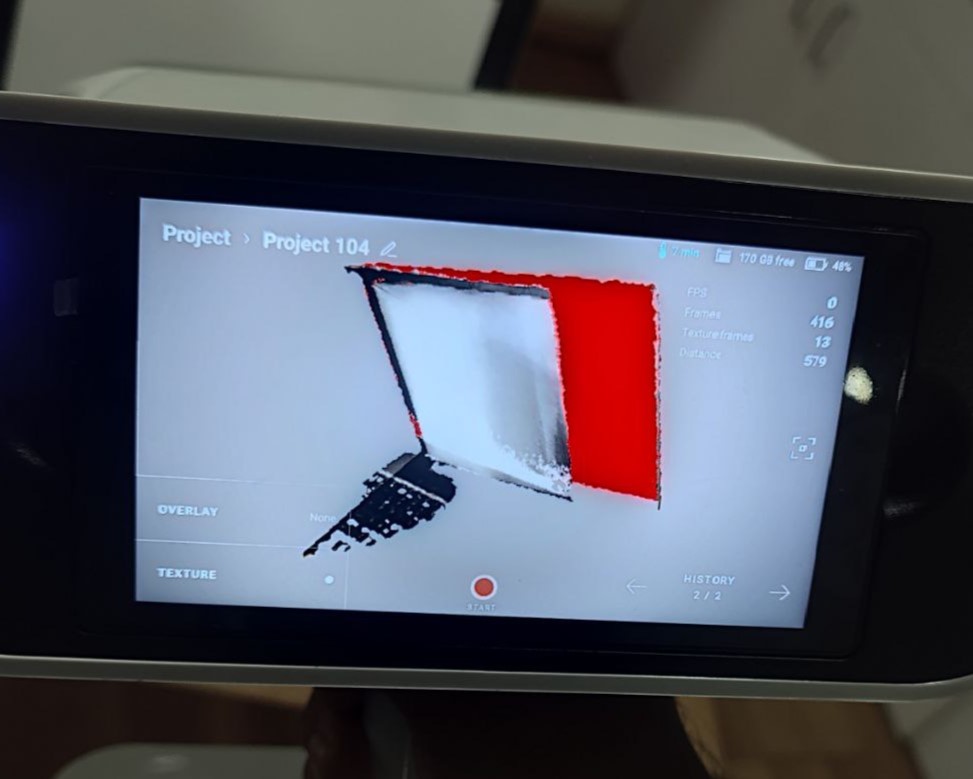
My first idea was to scan my laptop. I covered my screen with an A4 paper so that it won't absord the light. But once I completed scanning, I was able to notice some miscalculations, wherein, edges of the laptop screen were not read and the scanner miscalculated the distance between the front and back side of laptop. So, I thought of trying something else.
Model 2
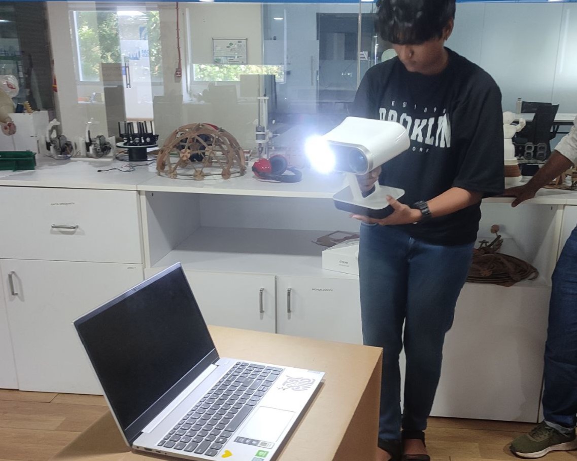
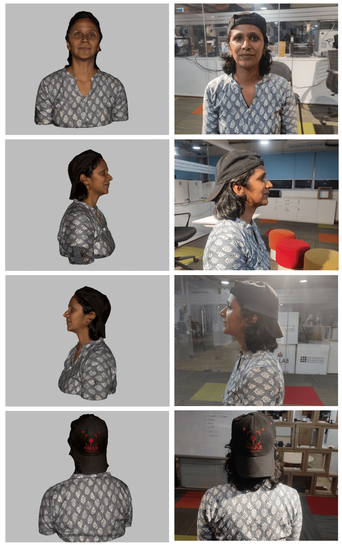
I thought of scanning a person and Ansu, my fellow mate from Fab Academy, was ready to be my muse. We got into a right setting where there was perfect lighting and started my work. I asked her to wear a cap as it is difficult to detect hair by the scanner. Ansu was patient enough to sit still throughout the process and with her co-operation I was able to wind up the process pretty quickly and also in one scan.
.jpg)
.jpg)
.jpg)
Post-Processing
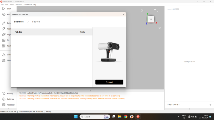
For post-processing, I used Artec Studio 15 Professional. First, I connected the Scanner to the system using LAN cable. Then, I imported the file into the software by selecting the Scanner.
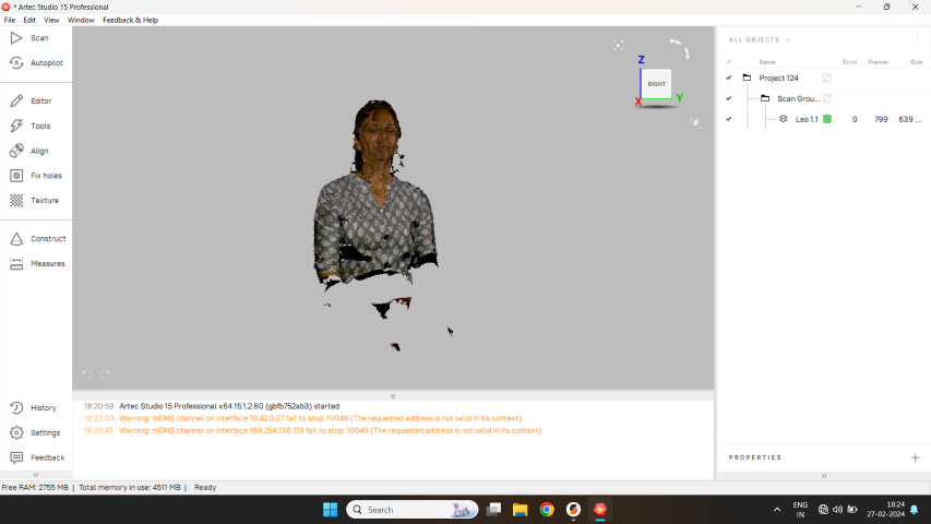
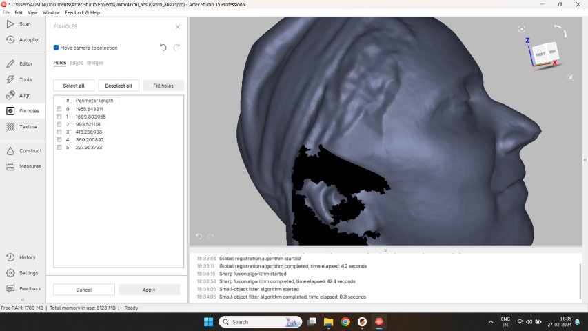
With the help of features like Eraser, Global Registration, Smooth Fusion and Texture, I was able to reconstruct the file into a presentable form.
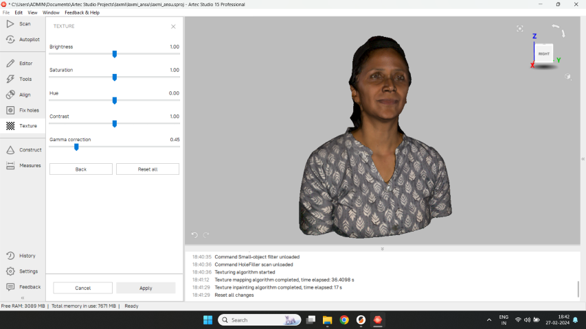
Result
Once I was satisfied with the editing, I exported the file in both .obj format as well as .stl file format.
OBJ Format: The OBJ file format, with the extension .obj, is a standard 3D image format that can be used to represent 3D geometry alone, including the position of each vertex, the UV position of each texture coordinate vertex, normals, and the faces that make each polygon defined as a list of vertices. If we export the file in this format, the texture will also be downloaded with it in .png file format.
STL Format: The STL (Stereolithography) file format is a widely used standard in the world of 3D printing and additive manufacturing. Developed by 3D Systems in the 1980s, the STL format simplifies the process of turning digital 3D models into physical objects by focusing solely on the surface geometry of a 3D object without including color, texture, or other common model attributes found in more complex file formats.
Next step was to print this model. I used Prusa i3 MKS for printing. I also made a separate file for base. Then, I imported both the files to the Prusa Slicer and aligned them. I planned on using two different filaments. So I gave the settings in the slicer for that and sliced it.
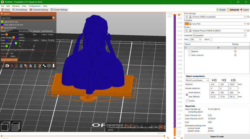
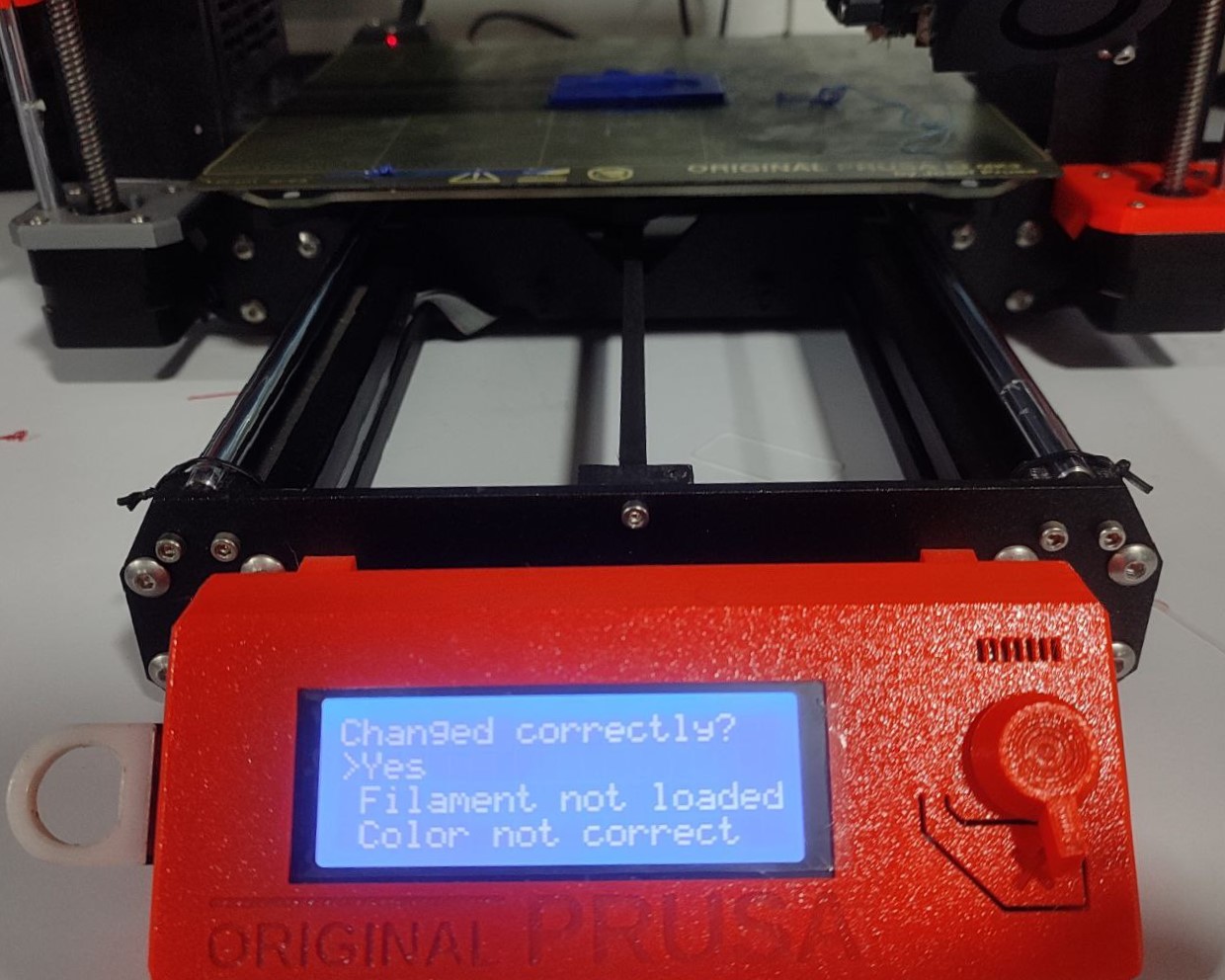
It took about 2 hours to complete including the filament change. When it was time to change the filament, the machine beeps and will start giving instructions on how to change the filament.
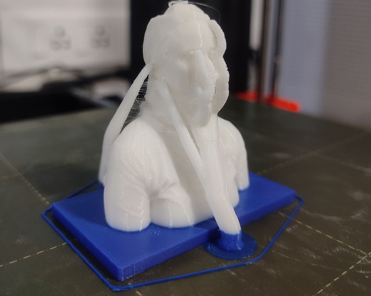
I used some tools to remove the organic supports provided on top of the printed model.
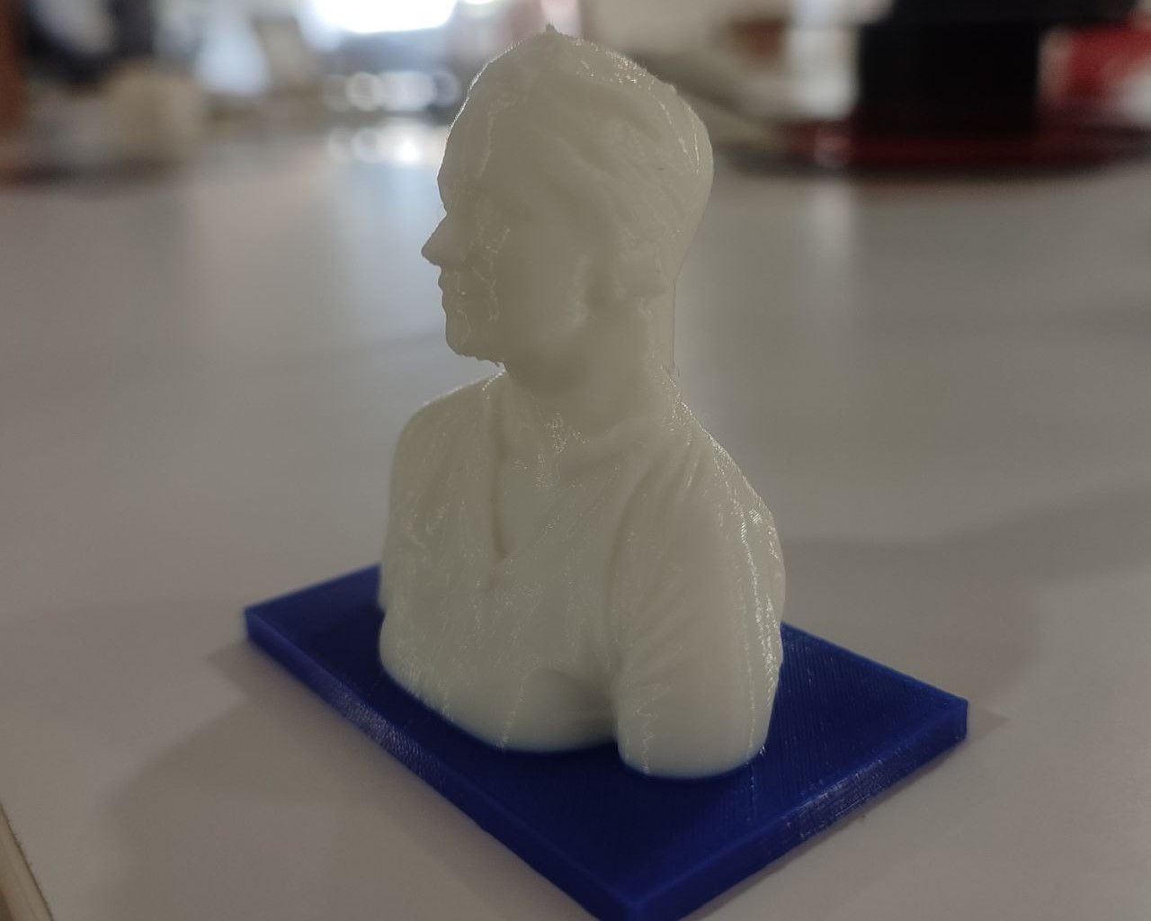
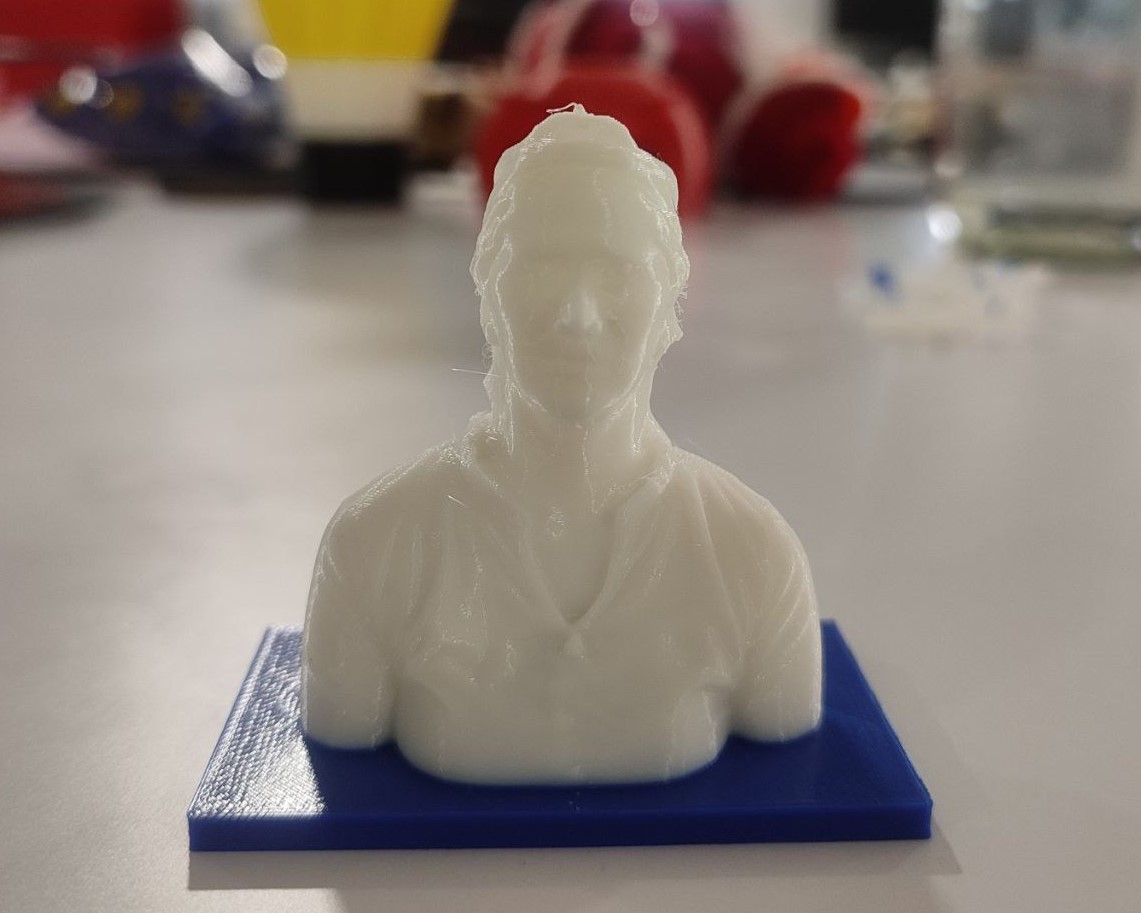
Here's the outcome:
Download Files
Ring Design File (.f3d file)
Gyroscopic Rings Design File (.f3d file)