Computer-Controlled Cutting
Objectives for Week 3
- Cut something on vinyl cutter
- Design, laser cut, and document a parametric construction kit
- Group Assignment: Characterize the laser cutter's focus, power, speed, rate, kerf, joint clearance and types
Group Assignment
Click for Group Assignment-Week 3Vinyl Cutting
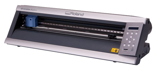
Roland GX-24
The Roland GX-24 Camm-1 Servo is a desktop vinyl cutter widely used in the sign making, apparel, and vehicle graphics industries.
To know more about the tool and its working, visit Roland GX-24 Fabcloud Page.
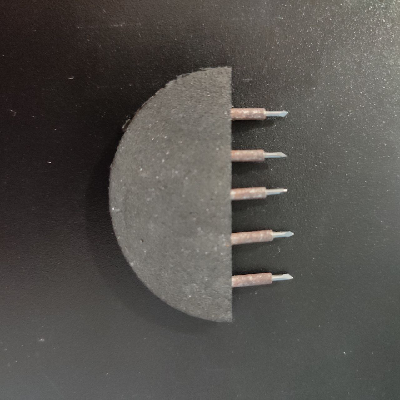
The blade in the Roland GX-24 vinyl cutter is a critical component, as it directly affects the quality and precision of cuts. When working with a Roland GX-24, understanding the types of blades and their maintenance is essential for achieving optimal results. Blades with 45 degree angle is a good-for-all purpose option and I have used the same blade for cutting.
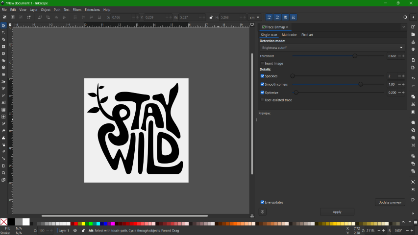
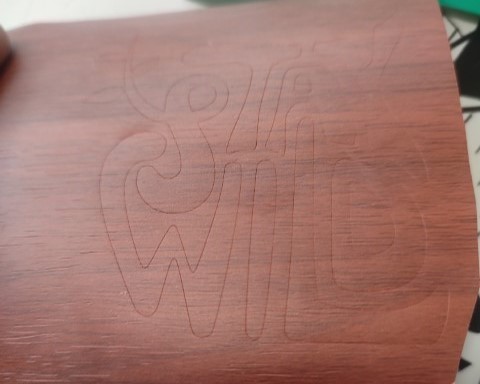
For this week, I tried cutting a small sticker for my laptop. So, there was this quote that I liked and I recently found great image of it and I thought I'll create a sticker. In order to use vinyl cutter, the image has to be in either .svg or .png format.
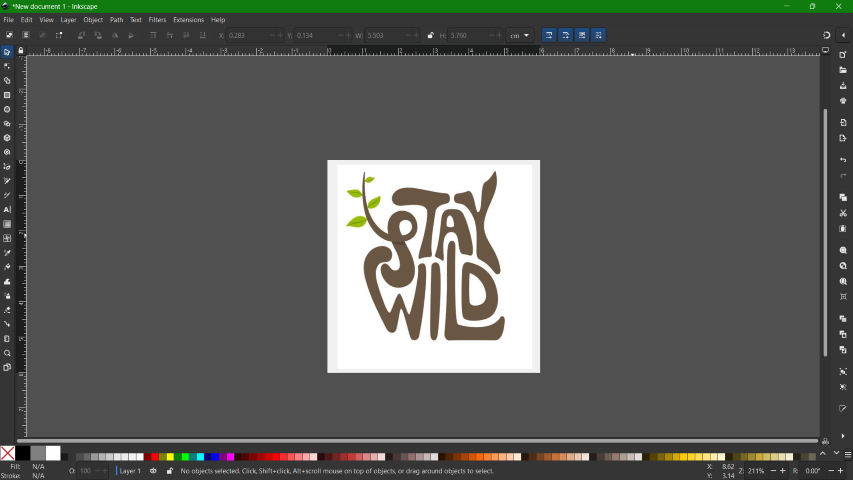
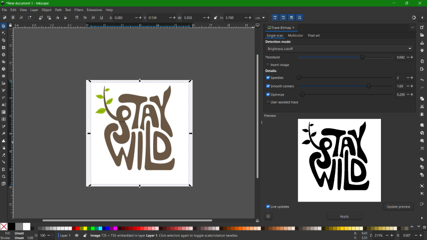
I used Inkscape to vectorize the image. Using 'Trace Bitmap' tool, I made a vector image and exported it as .png file.
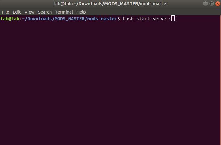
Next, I moved on to vinyl cutting. The Roland GX-24 comes with a dedicated software. But here in our lab we use MODS-Project. MODS Project or Fab Modules is an open source software that can be used to run any fab lab machines. It provided a set of software tools for designing 2D and 3D objects, functions to generate 2D and 3D toolpaths and GUI workflow from design files to machine commands. It is a much better alternative than installing and using different softwares for different machines. Once mods is downloaded, all you have to do is right click inside the folder to open the terminal and type the command as shown.
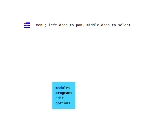
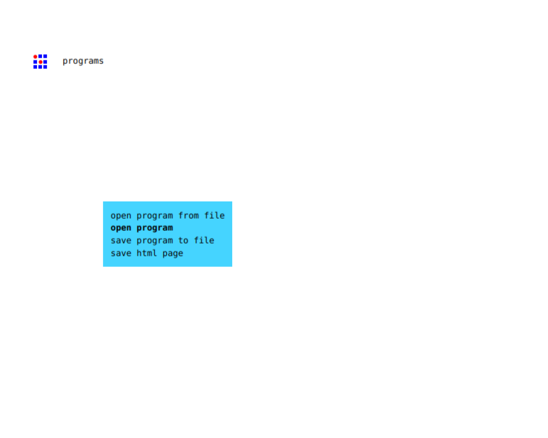
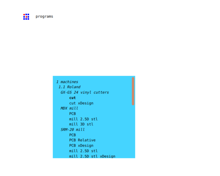
Once opened, right click to select programs>open programs>(the machine and the process).
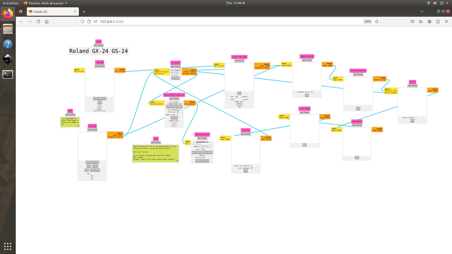
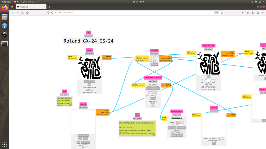
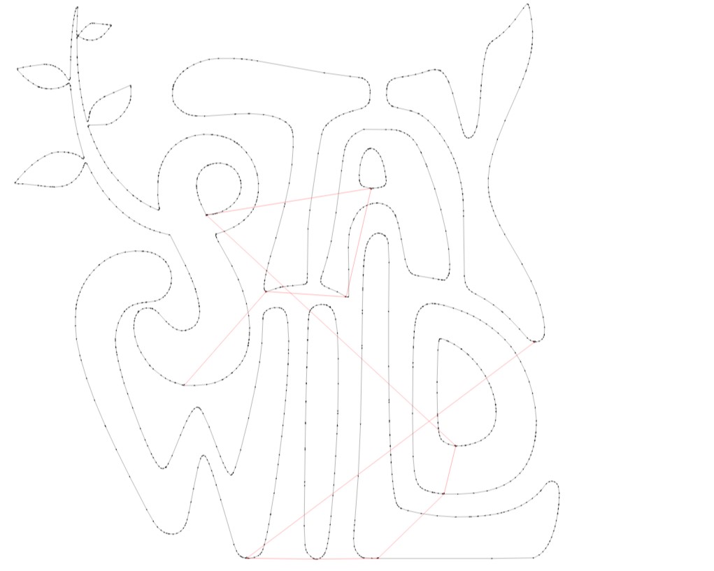
And you will get an interface as shown below. All you have to do then is to select the file, set the origin and values. There is a view option to see the path the vinyl cutter will follow to cut the image.
Then, the file was sent to the machine and the cut was done. Since, my sticker had two colours, I used two colour rolls.
After cutting, I removed the negative space first and then pasted masking tape over the sticker to transfer the sticker from the sheet.
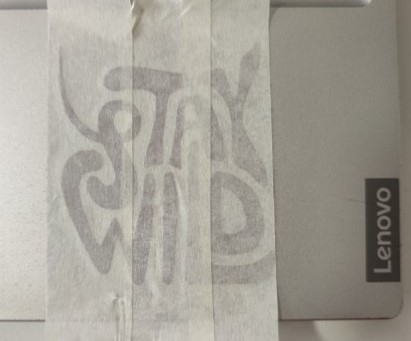
I pasted it on my laptop and carefully removed the tape.
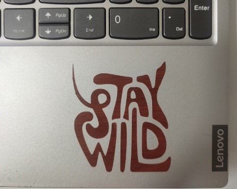
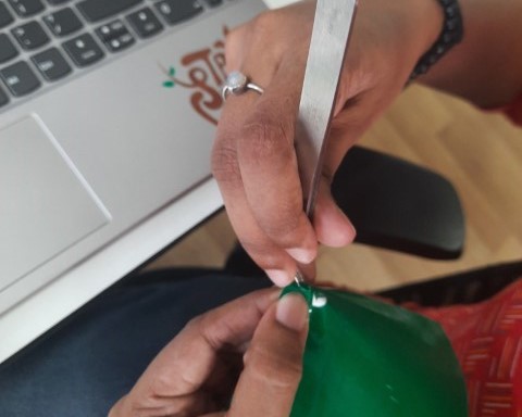
Likewise, I did the same process with the green roll. Here, since the green portion was so small, I used a tweezer to remove the green portion and sticked it on my laptop on its corresponding positions.
.jpg)
Laser Cutting
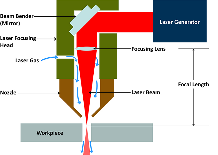
How a Laser Cutter works?
A laser cutter works by focusing a high-powered laser beam onto a material, which it either melts, burns, vaporizes, or is blown away by a jet of gas, leaving an edge with quality surface finish. The process is controlled and directed by computer numerical control (CNC) technology, allowing for precise cutting of complex shapes and designs.
Laser Generation
The laser beam is generated in the laser source, commonly through the stimulation of a gas mix (in a CO2 laser) or diodes and crystals (in a fiber laser). The laser beam is then directed towards the material through mirrors and a focusing lens, which concentrates the laser into a very small, precise spot.
Cutting Operation
The focused laser beam heats the material at the point of contact to an extremely high temperature, causing it to melt, burn, or vaporize. If a gas jet is used, it can help to eject the material from the cut, achieving a cleaner edge.
sourced from google
Trotec Speedy 400 flexx
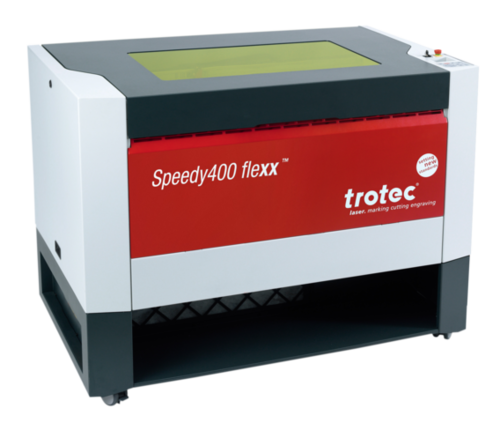
In our FabLab we have Trotec Speedy 400 Flexx. It is a highly versatile and advanced laser engraver and cutter designed for efficiency, precision, and flexibility in a wide range of applications. The "Flexx" functionality refers to its dual-source system, which combines both a CO2 laser and a fiber laser in one machine. This allows for the processing of different materials, including metals, plastics, and organics, without needing to change the laser source manually.
Specifications:
- Work Area: The Trotec Speedy 400 Flexx typically offers a work area of about 1000 x 610 mm (39.3 x 24.0 inches), providing ample space for a variety of projects and material sizes.
- Laser Power:
- CO2 Laser Options: Generally ranges from 60W to 120W, suitable for cutting, engraving, and marking on materials like wood, glass, acrylic, and leather.
- Fiber Laser Options: Power options can vary, often around 20W to 50W, ideal for marking and engraving metals and plastics.
- Speed:Speed: The Speedy 400 Flexx is designed for high-speed engraving and cutting, with the ability to reach speeds up to 4.3 m/s (169 in/s) and an acceleration of 5 g, ensuring high productivity.
Unfortunately, our laser machine isn't functioning and is under maintenance as the beam cannot penetrate the material to cut. Hence, we outsourced and used the laser machine available in Maker Village. But we had constraints in using it, so, we used the laser cutting machine for the group assignment and did my individual assignment using ZUND G3 L-2500 Digital Cutter in FabLab.
Parametric Construction Kit Design
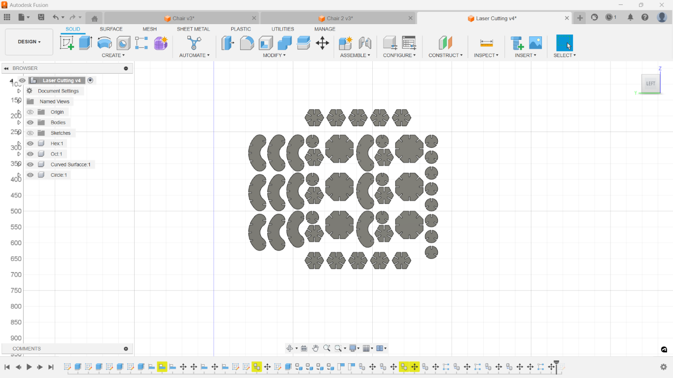
I used Fusion 360 to create my models for parametric construction kit. I created 4 elements for my kit.
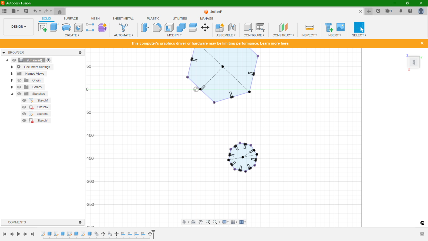
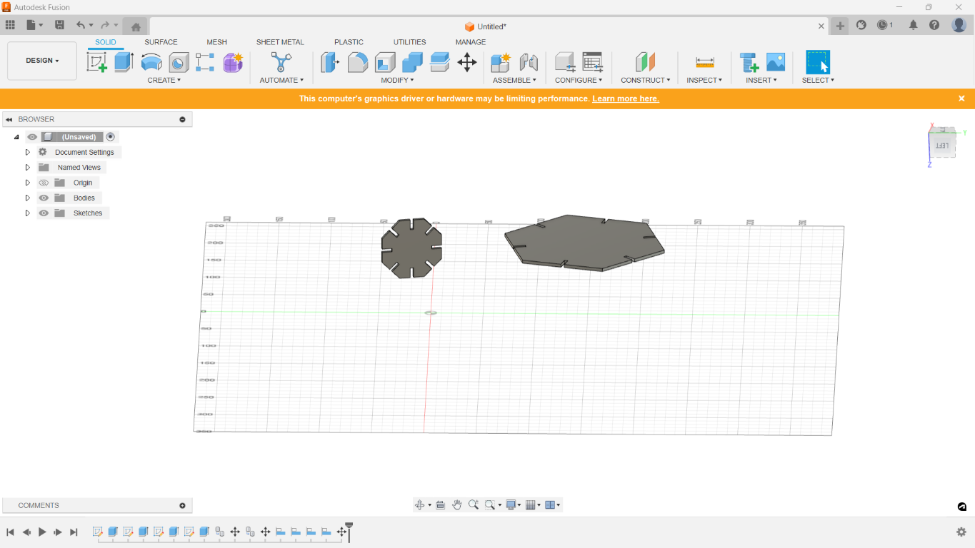
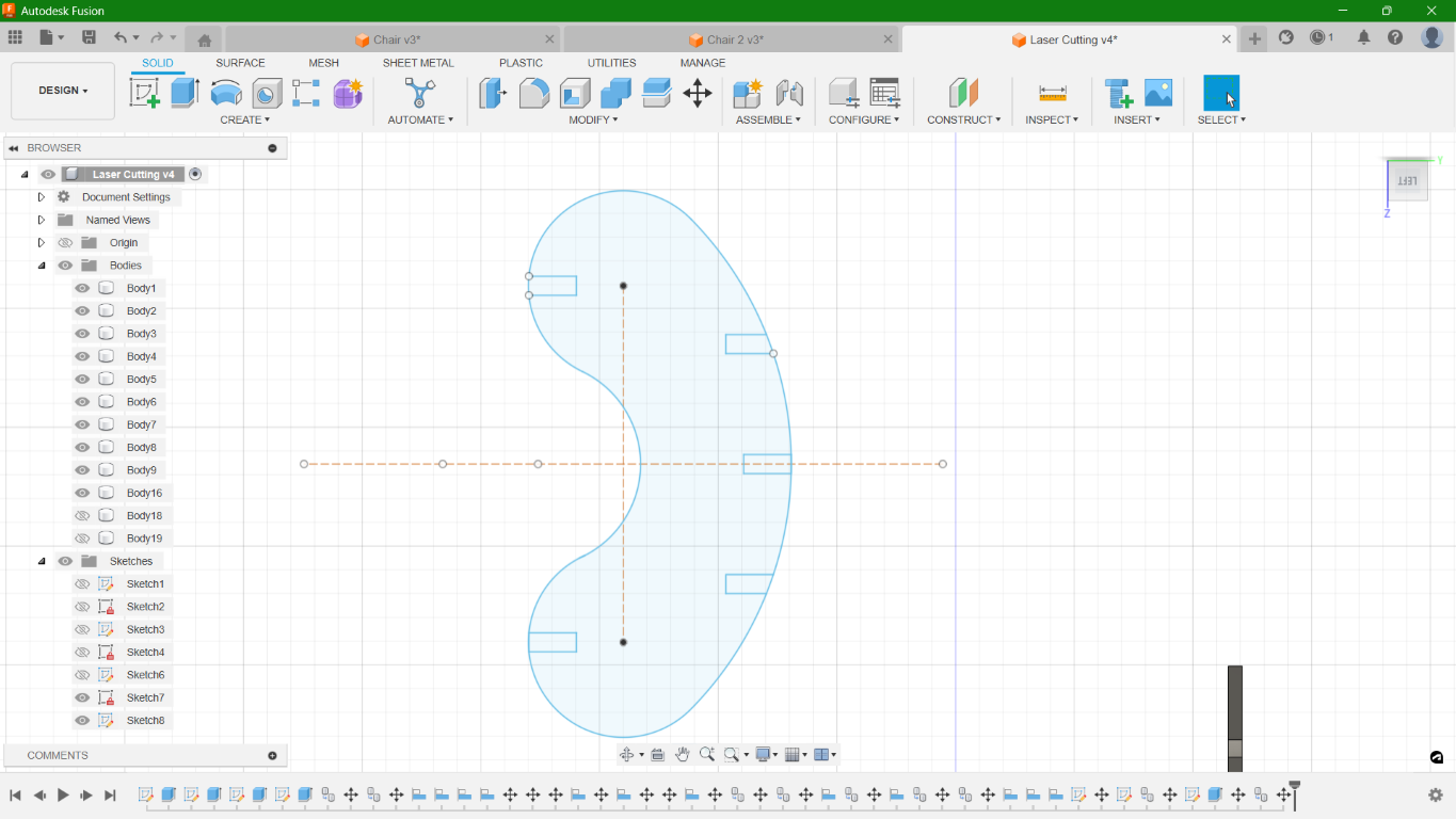
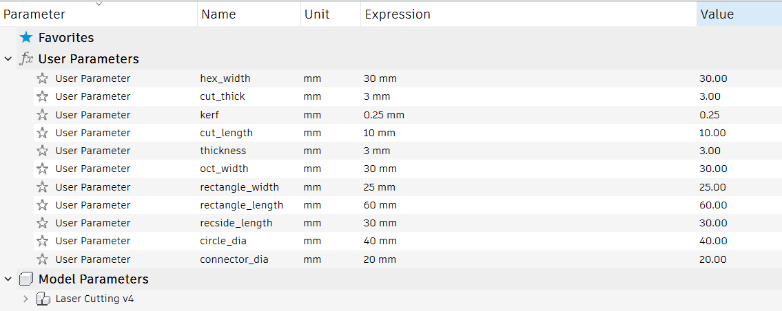
I used 'Parameters' option in Fusion to define set values like thickness, kerf, length, width and radius of my 4 elements. Parameters allow for easy modifications to the design by updating values in a central location, which can then automatically adjust all associated dimensions and elements throughout the project. This feature is particularly useful in engineering and design processes because it helps to maintain consistency and ensures that changes are propagated accurately across the model.
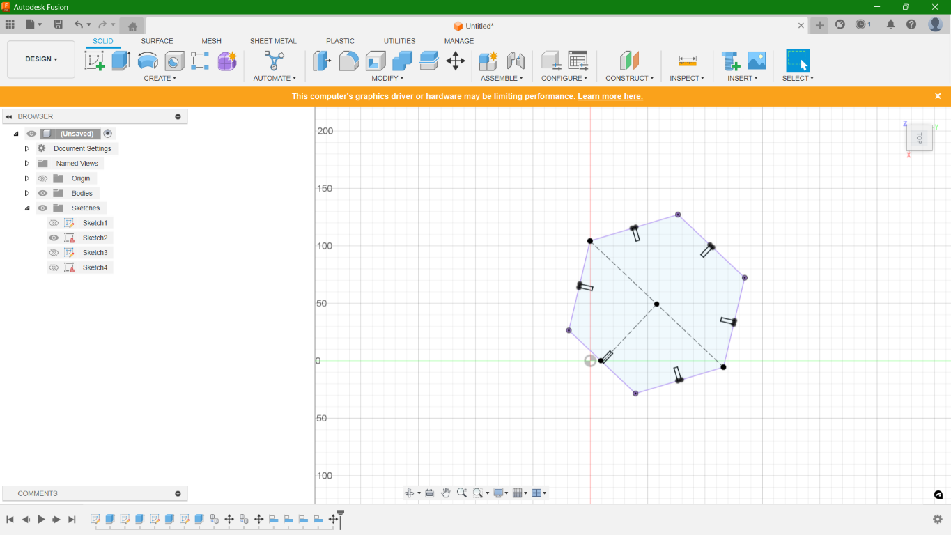
Once designing was complete, next task was to arrange the elements for cutting. For this, I arranged my four elements in a closed format. I created copies as per my requirement and arranged them manually for the cut.
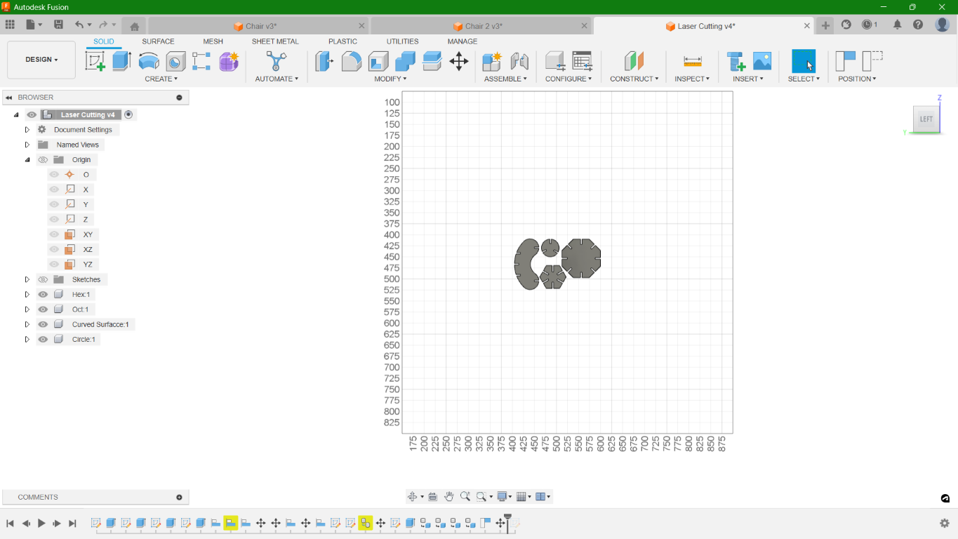
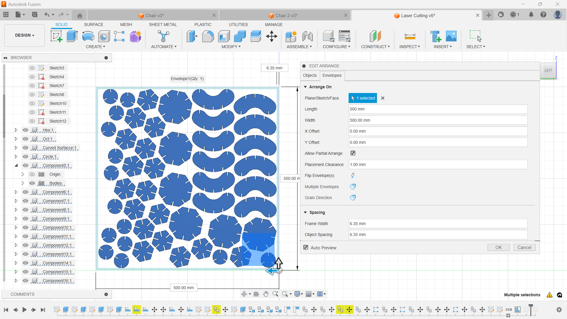
But then, I got to know from my instructor regarding the 'Arrange' option in Fusion which can arrange the components in such a way that the gap in between the elements will be small and thereby ensure less waste.
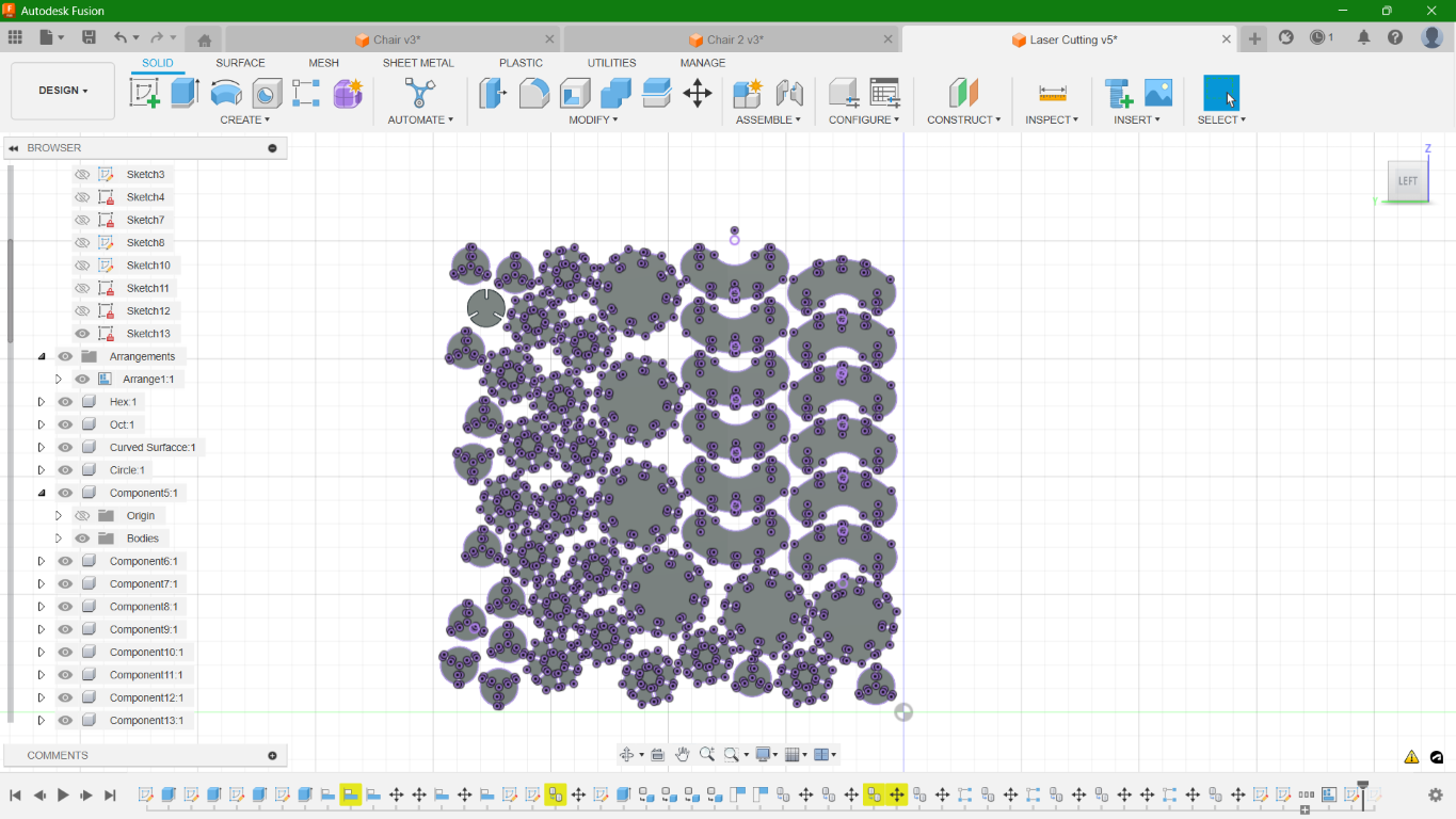
After arranging, I created a new sketch by projecting the surfaces of all the components and then exported the sketch in .dxf file format. The DXF file format, which stands for Drawing Exchange Format, is a type of graphic file format developed by Autodesk. DXF files are designed to represent two-dimensional (2D) and three-dimensional (3D) drawings and are composed of ASCII (American Standard Code for Information Interchange) or binary data, which describes a set of graphics or diagrams. In this case, the file contains the 2D design of the elements for cutting.
ZUND G3 L-2500 Digital Cutter
.jpg)
ZUND G3 L-2500 is type of digital cutting system that can be employed across a multitude of industries for cutting, creasing, and routing various materials like fabrics, plastics, metals, and composites.The main advantage of ZUND is that in a single process multiple operations by including different tool modules.
For my work, I used mainly three software parts in ZUND: Cut Editor, Cut Queue and Cut Centre. The process from importing the file to cutting the components where done respectively. The .dxf file was first imported in Cut Editor.
.png)
Once imported, I defined the processes that are going to be done by right clicking on the components Change Method > New Method. ZUND has different operations to choose from. So, we have to select the option Thru Cut for cutting. Next method is to provide Register to define the work area border, which was provided as border: front-right.
.png)
.png)
As the two methods were defined, I rearranged them according to the order in which it has to be done, where, first the border has to be defined and then cut.
In ZUND, the minimum distance between the corner is 5mm, but in my design I provided the slot width as 3mm. So, ZUND has an option to eliminate the overcut. In which, there are three options you can choose from: Waste Outside, Waste Inside and In each Corner.
.png)
Next step is to select the material. I chose corrugated cardboard with 3mm thickness as per the size of slots I have given.
.png)
Then I sent the file to Queue. Once opened, right click on the work to open it in Cut Center.
.png)
In Cut Centre, I verified all the details provided including the tool specifications. The tool module used in my work is an Electronic Oscillating Tool with Z21 knife. Once done, click on Start Job.
.png)
Then I positioned the tool to the front and right side of the cardboard sheet by jogging the gantry. The edge detection can be done automatically by the system or else we can manually set the border sides. Once done, the system will start cutting.
.png)
.png)
.jpg)
.jpg)
.jpg)
Kit Assembly
.jpg)
.jpg)
.jpg)
.jpg)
.jpg)
.jpeg)
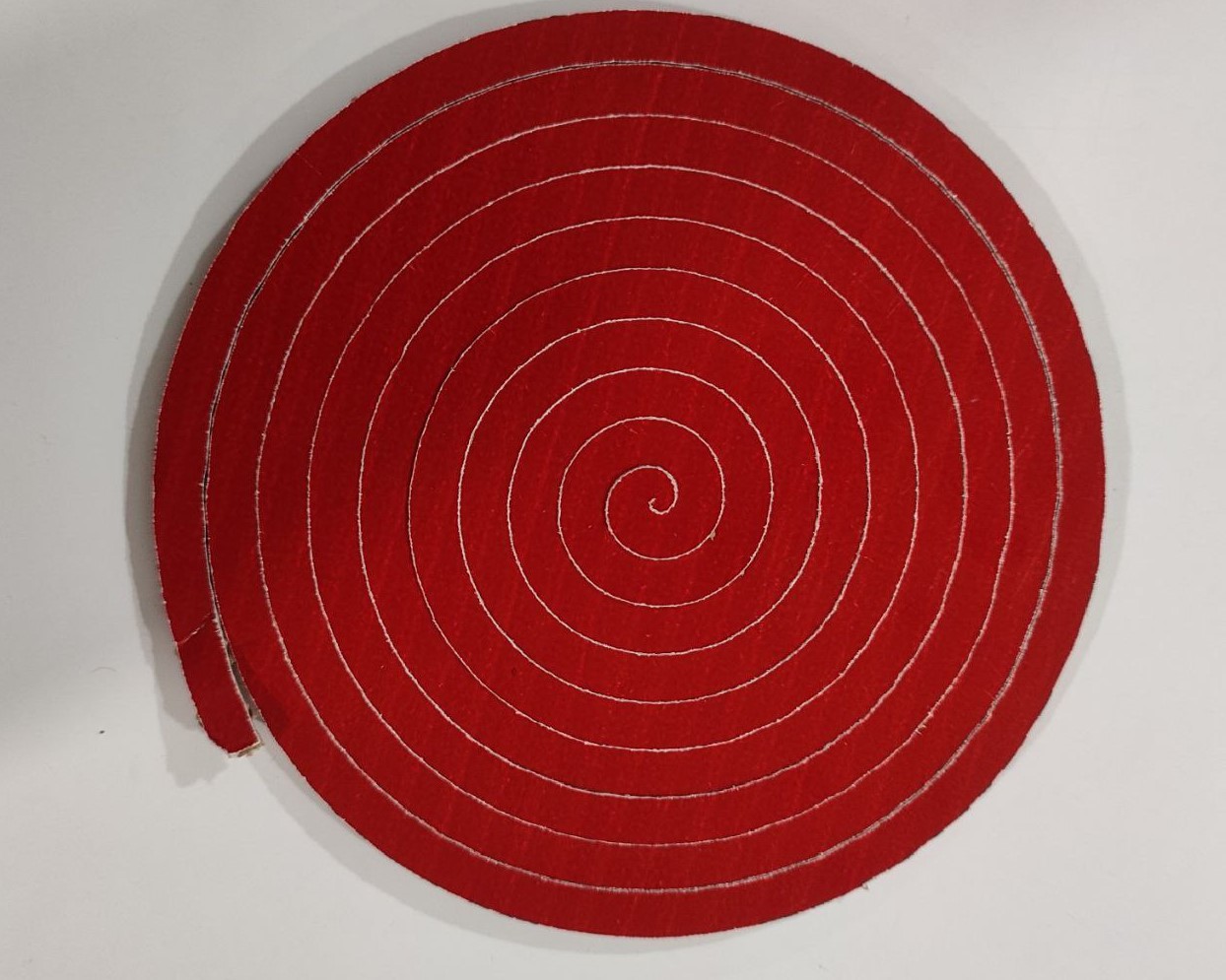
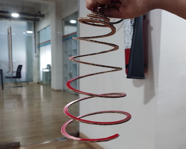
Fun Project
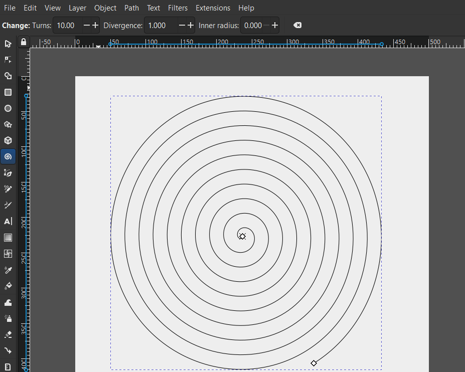
I tried cutting a spiral in ZUND. For that, I created the design in Inkscape. Press F9 to activate Spiral tool. On top you will get the option to change the number of turns, divergence ratio as well as inner radius. I chose 10 turns witha divergence of 1.
Once the design was completed, I exported the file in .dxf file format. Then, I imported the file in ZUND software and moved on to cutting the piece.
Download Files
Vinyl Cutting (.png file)
Parametric Construction Kit (.dxf file)
Spiral Cut (.dxf file)