Output Devices
Tasks for this week
- Individual Assignment: Add an output device to the microcontroller board we have designed and program it to do something
- Group Assignment: Measure the power consumption of an output device
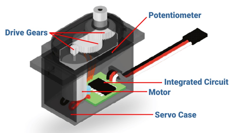
An Overview of Servo Motors
A servomotor is a rotary or linear actuator that can regulate angular or linear position, velocity, and acceleration with precision. [1] It is made comprised of an appropriate motor and a position feedback sensor. It also necessitates a complex controller, which is frequently a separate module created exclusively for servomotors. Although the word servomotor is typically used to refer to a motor appropriate for use in a closed-loop control system, it is not a specific type of motor. Servomotors are utilized in robotics, CNC machines, and automated manufacturing, among other uses.
How does servo motor works:
Servos are controlled by transmitting a variable-width electrical pulse across the control line, often known as pulse width modulation (PWM). There are three types of pulses: minimum, maximal, and repetition rate. A servo motor can only rotate 90 degrees in either direction for a total of 180 degrees.
Working Principle:
PWM ( Pulse Width Modulation ) is commonly used to control the angle of rotation in servo motors. PWM is a technique where the duty cycle of a square wave is varied to convey information. The duty cycle represents the proportion of time the signal is ON (high) compared to the total period of the signal.
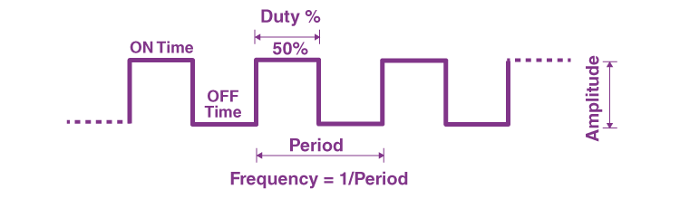
PWM (Pulse Width Modulation) signals are commonly used in microcontrollers to control the operation of various output devices such as motors, LEDs, etc. PWM works by rapidly switching a digital signal on and off at a fixed frequency, where the proportion of time the signal is on (duty cycle) compared to the total period determines the average power delivered to the load.
Here's how PWM signals control the angle of rotation in servo motors:
- Servo Control Signal : In the case of servo motors, the PWM signal typically has a fixed frequency (usually around 50 Hz) and a varying duty cycle. The width of the ON pulse within each cycle determines the position of the servo motor's shaft.
- Pulse Width Interpretation : Servo motors interpret the width of the PWM pulse as a command for the desired position. The typical range for the pulse width varies from around 1 millisecond to 2 milliseconds, although this can vary between different servo models.
- A pulse width of 1 ms might correspond to the servo's minimum angle (e.g., -90 degrees).
- A pulse width of 1.5 ms might correspond to the center position (e.g., 0 degrees).
- A pulse width of 2 ms might correspond to the maximum angle (e.g., +90 degrees).
- Continuous Updating : The control system continuously sends PWM signals to the servo motor. By adjusting the pulse width, the control system can rotate the servo motor shaft to the desired angle.
- Feedback Mechanism : Some advanced servo motors incorporate feedback mechanisms such as potentiometers or encoders. These mechanisms provide information about the actual position of the servo motor shaft, allowing for more precise control and feedback loops to ensure the motor reaches and maintains the desired position accurately.
In summary, PWM signals control the angle of rotation in servo motors by varying the width of the ON pulse within each cycle, with different pulse widths corresponding to different desired positions of the servo motor's shaft.
Below is the pin configuration for the ATtiny1614 microcontroller, which I'll be utilizing throughout this week.
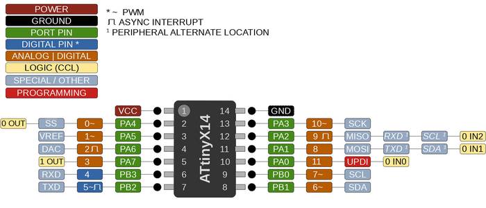
This week, the output devices I'm employing are dependent on PWM (Pulse Width Modulation) signals for control. It's essential to grasp the concept of PWM signals for a comprehensive understanding of their functionality.
PCB Design
During 'Electronics Design' week, I was introduced to KiCad to design PCBs. So I used the same tool this week. The first task is to identify the required components, apart from the driver and the microcontroller. Once that was done, I started with the schematic diagram.
.png)
Then I continued with the PCB editor to draw the traces. Here is the output after routing the necessary tracks.
.png)
.png)
I used Gerber Viewer to transform the Gerber files into PNG format. To understand the process, check out the documentation for Week 8. After converting the files, I milled the PCB.
PCB Milling
The next step is milling the PCB. I am using Roland Modela MDX20 along with MODs for the purpose. I already have some experience in using both during Electronics Production and Electronics Design weeks.
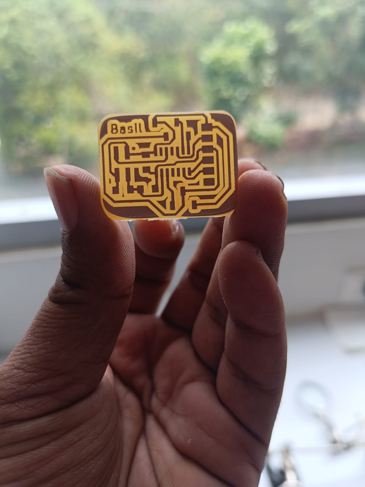
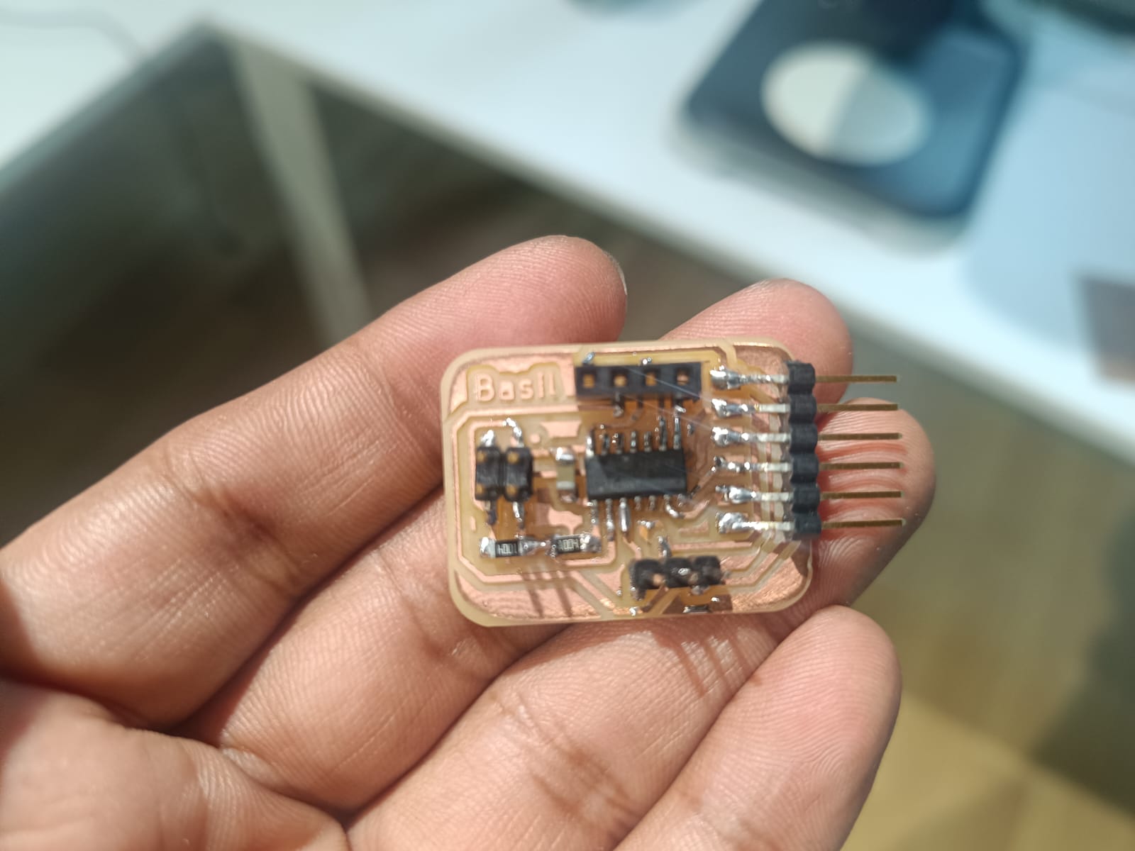
look what i got
The following step involves submitting a request to Fab Inventory for the necessary components. Here is the list of components:
.jpeg)
Final Result
Programming
I use Ardiuno IDE for stepper motor programming
Since the ATtiny board can't be connected directly to the system, I used the Quentorres board as a programmer. I followed the instructions in the link below to set everything up in Arduino.
https://wolles-elektronikkiste.de/en/using-megatinycore
I took the URL "
http://drazzy.com/package_drazzy.com_index.json" from the site and pasted it into "Additional Boards Manager URLs" in File > Preferences.
After that, I downloaded a package from the Boards Manager.
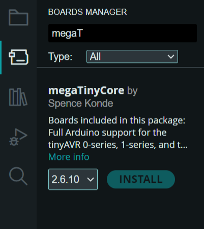
Once the package is downloaded, click on Tools > Board Manager > megaTinyCore > ATtiny3224/1624/1614/1604/824/814
.png)
Next select the chip, Tools > Chip > ATtiny1614
.png)
Select the programmer as SerialUPDI - SLOW: 57600 baud
.png)
The next step involves connecting the new board to the Quentorres, followed by linking it to the system. Since the Quentorres lacks a UPDI pin, we'll use an FTDI to UPDI converter from our FabLab to bridge the connection.
.jpeg)
Then I connected it to the system, selected the port and click on Burn Bootloader.
here i got the sample code for servo
The program moves the servo motor back and forth between 0 and 140 degrees. It does this by generating PWM signals with pulse widths corresponding to the desired angles. The servoPulse function is responsible for creating these PWM signals, while the loop function dictates the sequence of angles to which the servo should move.
The equation pwm = (angle * 11) + 500 converts the angle (0-140 degrees) into a pulse width in microseconds. This conversion is based on the specific requirements of the servo motor being used. Typically, servos require pulse widths between 1000 microseconds (1 millisecond) and 2000 microseconds (2 milliseconds) to cover the full range of motion (0 to 180 degrees). In this case, the values are adjusted for a range of 0 to 140 degrees.int servo = 3;
int angle;
int pwm;
void setup()
{
pinMode(servo, OUTPUT);
}
void loop ()
{
for (angle = 0; angle <= 140; angle += 5) {
servoPulse(servo, angle); }
for (angle = 140; angle >= 0; angle -= 5) {
servoPulse(servo, angle); }
}
void servoPulse (int servo, int angle)
{
pwm = (angle*11) + 500; // Convert angle to microseconds
digitalWrite(servo, HIGH);
delayMicroseconds(pwm);
digitalWrite(servo, LOW);
delay(50); // Refresh cycle of servo
}Here is the setup
.png)
Here is the video output of the servo motor
Group Assignment
For further details, click on the link for group Documentaion- Group Assignment-Week 9
.jpg)
In this experiment, we measured the power consumption of a Stepper motor under different conditions by recording the current and voltage values and calculating the power using 𝑃=𝑉×𝐼. The results show a linear increase in power consumption with increasing current, which is visually represented in the graph.By understanding the power consumption characteristics of the Stepper motor, we can better optimize its performance and ensure efficient energy usage in practical applications.