Electronics Design
Tasks for this Week
1.Individual Assignment:Use an EDA tool to design a development board to interact and communicate with an embedded microcontroller, produce it, and test it
- Extra credit: try another design workflow, design a case for it and simulate its operation
- Extra credit: design a case for it.
- Extra credit: simulate its operation.
2.Group Assignment: Use the test equipment in your lab to observe the operation of a microcontroller circuit board
Group Assignment
This week's group assingment was to use the test equipments in our lab to observe the operation of a microcontroller circuit board.
.jpg)
For further details- Week 8 Group Assignment
Circuit
Imagine a closed loop like a racetrack. This loop is a circuit, a path for tiny charged particles called electrons to travel. The electricity comes from a source, like a battery, and flows through components that use or control the energy.
There are two main types of circuits:
- Electrical Circuits: These use basic components like resistors, capacitors, and inductors. Think of them as the building blocks for electrical systems. An example is a simple circuit with a battery and a light bulb.
- Electronic Circuits: These can include electrical components but also fancier ones like transistors and diodes. They are more complex and often used in devices like computers and smartphones. An LED circuit with a battery and resistor is a basic example, even though LEDs are considered electronic components.
Circuits can also be categorized by the signals they handle:
- Analog Circuits: These deal with continuous, smooth-changing signals, like the sound waves traveling through your headphones. Imagine the volume knob on your radio - it controls the strength of a continuous analog signal.
- Digital Circuits: These work with signals that are either on or off, like a light switch. Your computer uses digital circuits to process information in the form of 0s and 1s.
Power Supply
The provision of electrical energy to various components within a circuit is facilitated by a power source. Power sources exhibit diverse forms, including batteries, generators, power supplies, and solar cells. Additionally, connections such as USB interfaces to laptops and power sockets through adapters & USB can be regarded as alternative power sources.
Resistor
A fundamental component within electrical circuits, a resistor serves the function of impeding the flow of electrical current. Its design aims to diminish voltage and current levels within the circuit while regulating the dissipation of electrical energy in the form of heat. The behavior of resistors adheres to Ohm's Law, which stipulates that resistance equals voltage divided by current: R = V / I. Furthermore, employing the power formula allows the expression of power as P = V * I = R * I^2.
Capacitors:
Think of capacitors as tiny batteries that can charge and discharge quickly. They're made of two metal plates separated by a material that doesn't conduct electricity. These components are like electric storage tanks, used in many devices to keep the electricity stable. They're crucial because they help smooth out any bumps or dips in power, ensuring devices work properly.
Diodes:
Diodes are like electrical valves, allowing current to flow in one direction but blocking it in the other. They're made from special materials that only let electricity move through them in a particular way. Diodes are found in lots of electronics, making sure electricity flows where it's supposed to. They're used in things like converting AC power to DC power and controlling signals in circuits.
Microcontrollers
A microcontroller is a small computer on a single integrated circuit (IC) that is designed to control a specific system or device. It is a specialized computing device that is designed to control a specific system or device. It typically includes a processor, a small amount of memory, and input/output peripherals such as timers, serial communication interfaces, and analog-to-digital converters, all of which are integrated onto a single chip. Microcontrollers are typically programmed to perform specific tasks, and run specialized software known as firmware.
Microcontrollers are used in a wide range of electronic devices, including smartphones, automotive systems, home appliances,industrial automation equipment, and more. They are also commonly used in embedded systems, which are computer systems that are integrated into other devices or products to provide specific functionality.
One of the key benefits of using microcontrollers is that they can be programmed to perform specific tasks, which can greatly enhance the functionality of a device. They are also cost-effective, consume less power than traditional computers, and can be easily integrated into electronic systems.
SAMD11
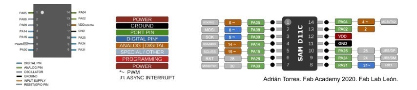
My development board uses a SAM D11 microcontroller, a tiny chip from Microchip Technology. It's part of a family of microcontrollers called SAM D, and they're known for being efficient with power. This makes them ideal for projects where battery life is important.
SAM D11 microcontrollers are like the brain of many devices, including those in the "Internet of Things" (IoT) and everyday electronics. They're powerful enough for many tasks but use less energy than some other options. They also have built-in features like converters (ADCs), communication ports (UARTs, SPI, I2C), timers, and general-purpose input/output pins (GPIOs) that make them adaptable for various uses.
To understand how to use the SAM D11 on my board, I consulted a pinout diagram, which is like a map that shows the location and function of each pin on the chip. This helps me connect things to the microcontroller and make it work in my design.
Learning PCB Design with KiCad
This week, we dove into the world of Printed Circuit Boards (PCBs)! Our instructor, Saheen, started by explaining the fundamentals of electronics and the tools needed for the design process. Although I was initially nervous due to my limited experience, Saheen's clear guidance helped me navigate each step.
KiCad: Our PCB Design Software
For PCB design, we were introduced to KiCad, a free and open-source Electronic Design Automation (EDA) software. KiCad allows you to create schematics (diagrams) of electronic circuits and then convert them into physical PCB layouts. You can download KiCad here (link omitted to respect your privacy).
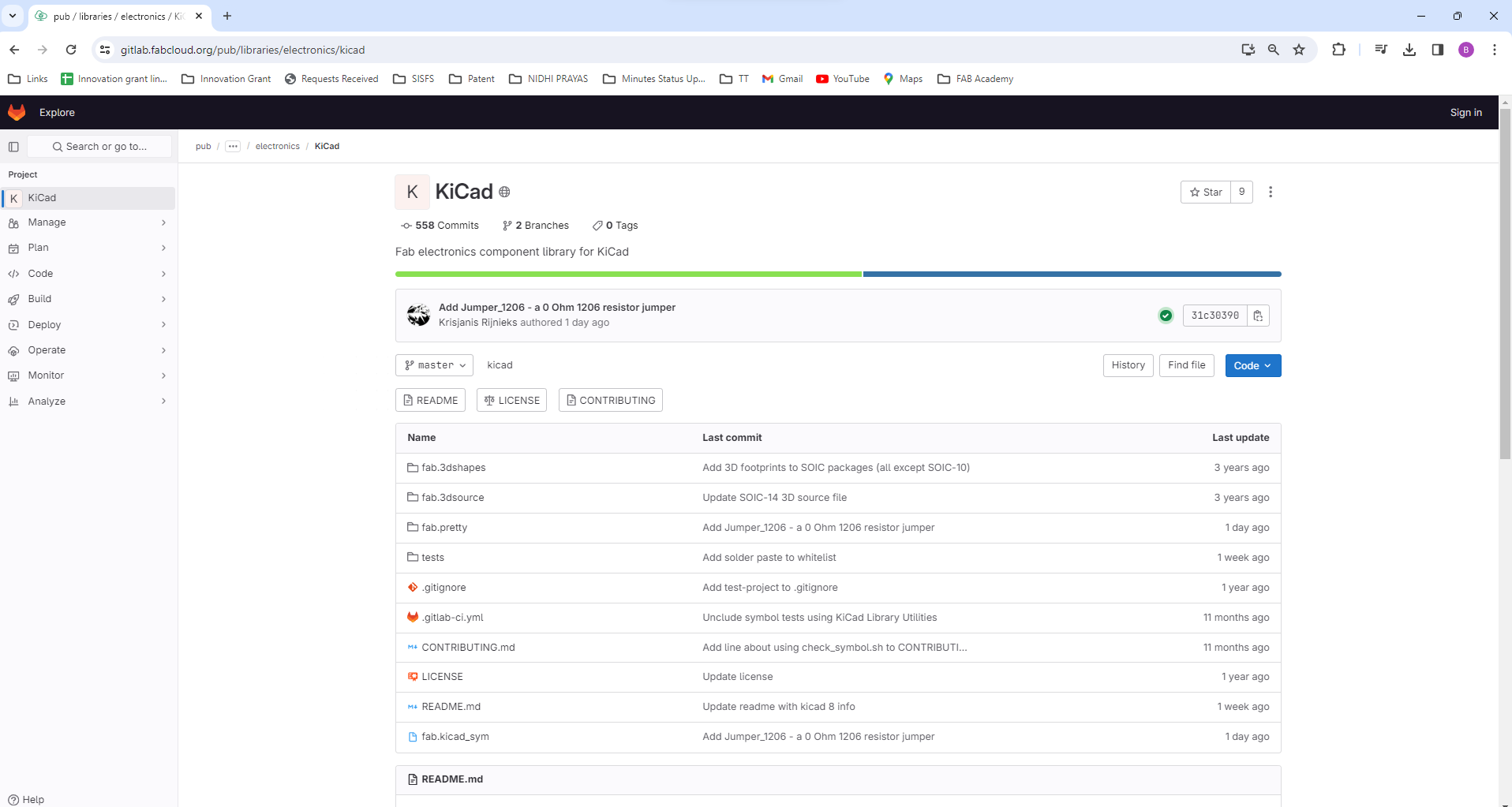
Downloading Fab Academy's KiCad Library
To streamline the design process, Fab Academy provides a library of symbols and footprints specifically for KiCad. I downloaded this library as a .zip file from the following link -https://gitlab.fabcloud.org/pub/libraries/electronics/kicad
Adding Libraries to KiCad
Once you have KiCad open, you can easily integrate these libraries into your projects. Here's how:
- For Symbols: Go to "Preferences" > "Manage Symbol Libraries" > "Add file" and select the downloaded symbol library file.
- For Footprints: Follow the same steps, but navigate to "Preferences" > "Manage Footprints Libraries" > "Add file" and choose the footprint library file.
With these libraries loaded, you'll have a wide range of electronic components readily available for your PCB designs in KiCad!
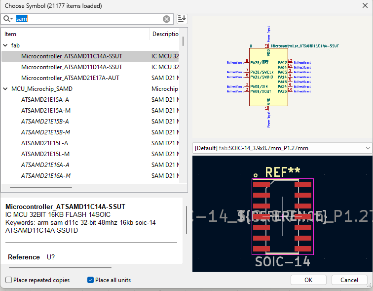
For this week, I have selected the SAMD11C microcontroller for my design project. The SAMD11C belongs to a family of low-power microcontrollers built upon the ARM Architecture. The ARM architecture lays down a comprehensive framework governing the interaction between software and hardware, delineating how instructions are executed within the hardware.
I commenced my design process by accessing the schematic file and proceeded to integrate the requisite components.
.png)
By pressing 'A', I accessed the symbols library, finding all the necessary symbols categorized under the 'fab' group."
I started joining the connection of the microcontroller by Add Wire / by clicking W in keyboard
.png)
Schematic Diagram
For this week i have used a voltage regulator
SAMD11 runs on 3.3V but the laptop output voltage is 5 V. To regulate the voltage, I referred this design so my board would not damaged.
I used the breakout board I have soldered during Week 4 for my work here.
.png)
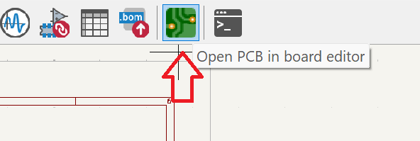
Once the schematic diagram was complete, the next step was to design the PCB and add the traces. To do this, click on the "Open PCB in board editor" icon located at the top right corner.
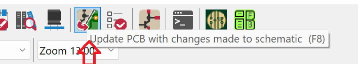
Upon opening the PCB editor, a new screen appears. To update the PCB with the changes made in the schematic, click on the "Update PCB with changes made to schematic" icon located at the top right corner. Then press "Update PCB" to synchronize the changes between the schematic and the PCB layout.
The next step involves defining the constraints and parameters for PCB design.
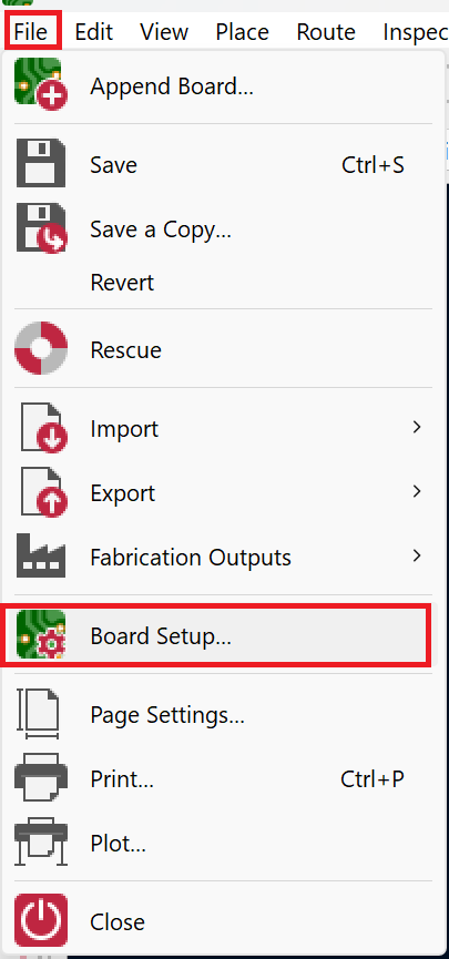
To add the constraints, navigate to the board setup menu and select "Constraints." This allows you to define specific design parameters
Based on the capabilities of our milling machine identified during the "Electronics Production" week, the values are as follows:
.png)
These constraints and parameters ensure compatibility with our milling machine's capabilities and allow for accurate fabrication of the PCB.
I started traced the PCB board by pressing “X” in my keyboard
.png)
.png)
.png)
I export the Gerber file of the PCB using the below Steps
- File —>Fabrication Output—> Gerbers
.png)
Then clicked Plot and Genereate Drill files and Map files
.png)
The subsequent action involves milling the PCB, requiring the file to be in either .png or .svg format. However, this conversion can't be directly executed from KiCad. My friend Midhlaj has developed an online tool for converting gerber files to png format.
The Gerber Viewer facilitates the conversion of gerber files into png format. Initially, I exported the PCB design as gerber files and subsequently imported them all into the gerber viewer.
.png)
After selecting the " Generate PNG " option, the web application will generate the PNG file, which can be downloaded and utilized for milling purposes.
For the cut file, select the "Top Cut" option.
After successfully generating the PNG file for PCB milling, I proceeded with the PCB milling process.
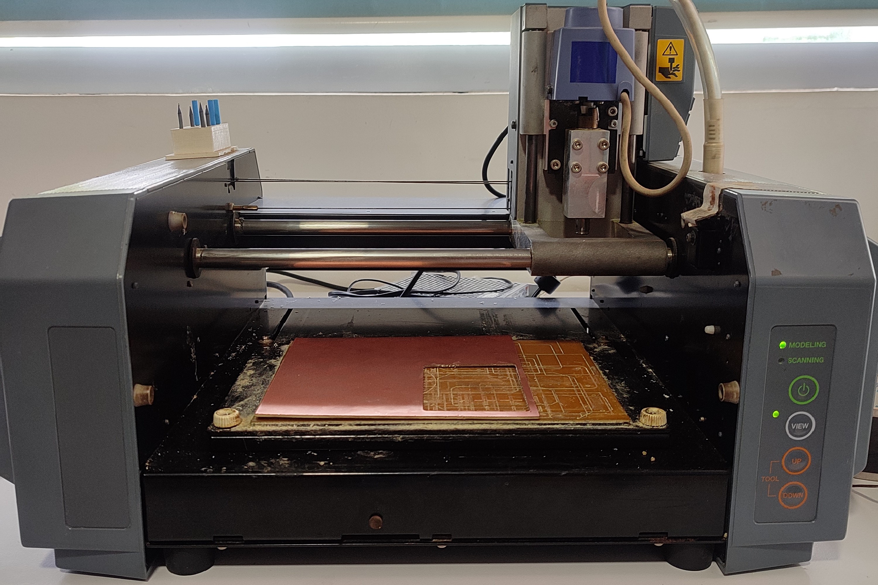
Milling
The next step is milling the PCB. I am using Roland Modela MDX20 along with MODs for the purpose. I already have some experience in using both during "Electronics Production" week.
Refer documentation of Week 4 to know about the working processes of Roland Modela MDX20 and MODs.
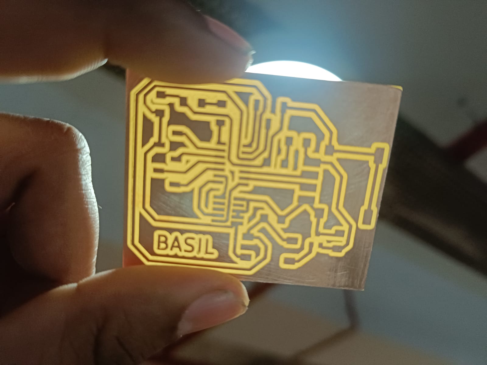
The surface quality following milling wasn't satisfactory, so I proceeded to sand down the PCB. Here are the results
So, now that the PCB is prepared for soldering, I have collected all the necessary components from the lab. Here's a list of the components I've gathered:
.jpeg)
During "Electronics Production" week, I learned soldering and enjoyed it. I was excited to do it again this time.
.jpeg)
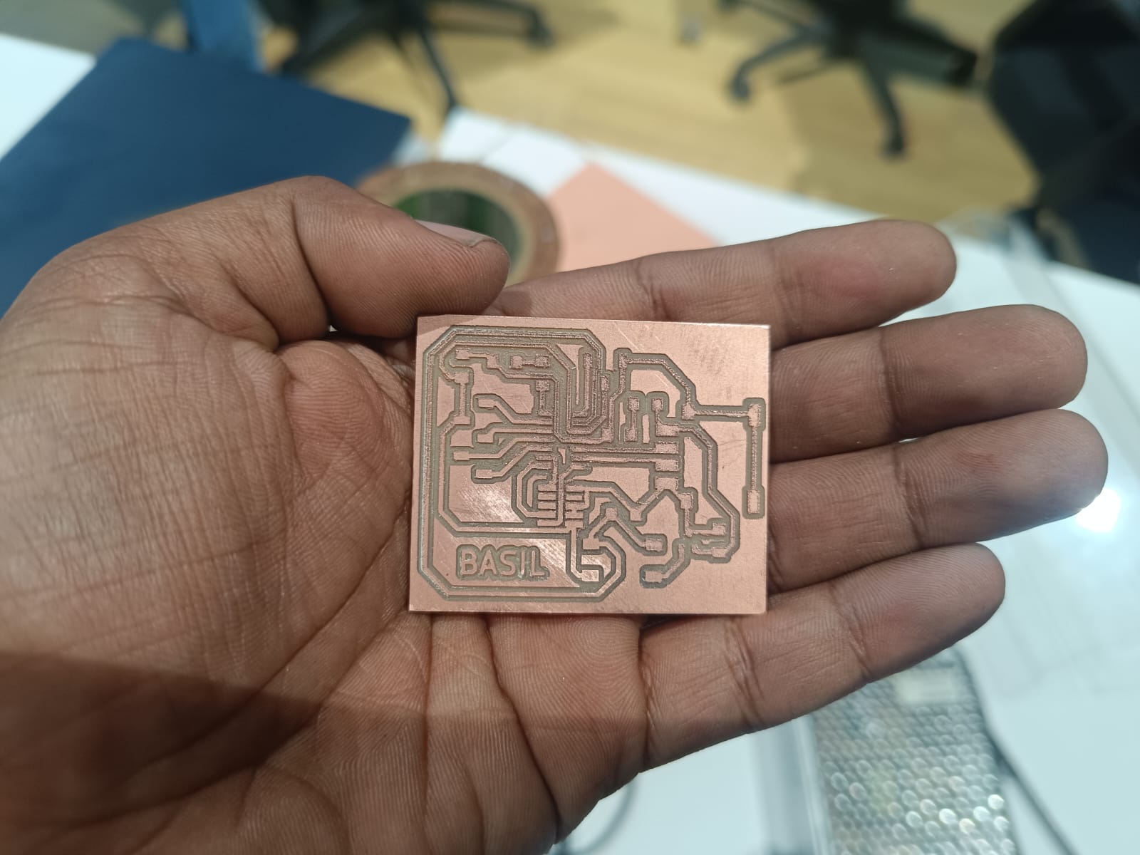
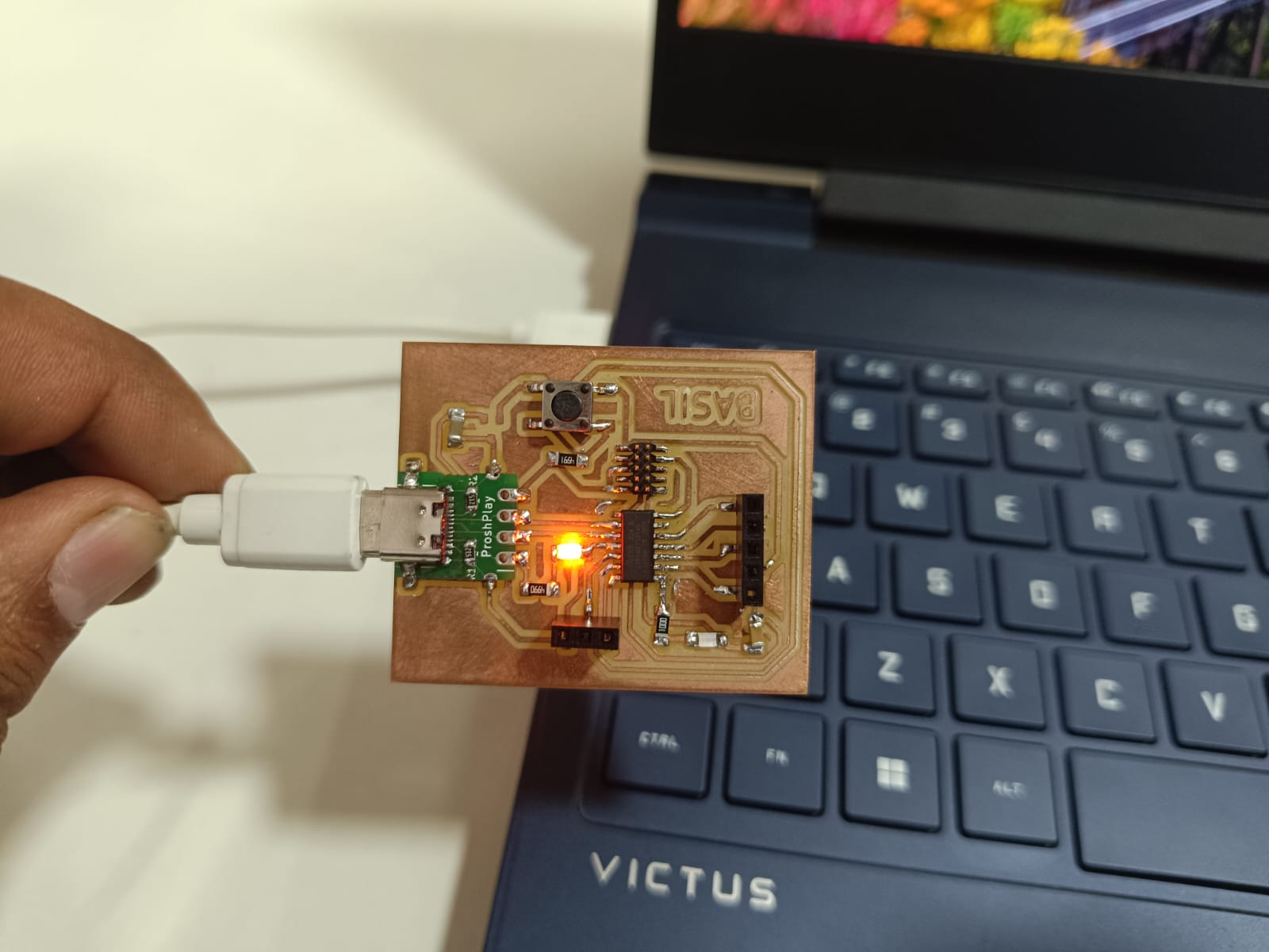
Look what i have made
.jpeg)
Programming the Board
To utilize the PCB, the initial step involves flashing the bootloader. To accomplish this, we utilize the Quentorres board as the programmer. Following the instructions outlined in the Quentorres documentation, I configured the board as a programmer. Initially, I established a connection between the Quentorres board and the new board using a 10-pin connector.
Next I pasted the below link to add the board in Arduino IDE. https://raw.githubusercontent.com/qbolsee/ArduinoCore-fab-sam/master/json/package_Fab_SAM_index.json
I installed the below file from the "Board Library".
.png)
Next I selected the board from Tools > Board > Fab SAM core for Arduino > Generic D11C14A.
.png)
The programmer was changed to CMSIS-DAP.
.png)
Then clicked burn the bootloader
.png)
After verifying that the onboard LED was blinking correctly, I proceeded to test the push button on the board. To do this, I utilized code from examples, edited the pin number to match the one on the board, and gave it a try.
This is the code i have uploaded to the board
const int buttonPin = 09;  // the number of the pushbutton pin
const int ledPin_1 = 02;   // the number of the LED pin 1
const int ledPin_2 = 05;    // the number of the LED pin 2
int buttonState = 0;       // variable for reading the pushbutton status
bool pressed = false;
void setup() {
  pinMode(ledPin_1, OUTPUT);  // initialize the LED pin1 as an output:
  pinMode(ledPin_2, OUTPUT);  // initialize the LED pin2 as an output:
  pinMode(buttonPin, INPUT);  // initialize the button pin as an input:
}
void loop() {
  buttonState = digitalRead(buttonPin);  // read the state of the pushbutton value:
  if (buttonState == HIGH)               // check if the pushbutton is pressed. If it is, the button state is HIGH:
  {
    if (pressed == false) {
      pressed = true;
      if (digitalRead(ledPin_1) == LOW)  // check whether the led1 is off, if it is then the LEDs will be HIGH
      {
        digitalWrite(ledPin_1, HIGH);
        digitalWrite(ledPin_2, HIGH);

      }
      else {  // if led1 is on then it will turn off all the LEDs
        digitalWrite(ledPin_1, LOW);
        digitalWrite(ledPin_2, LOW);
      }
    }
  } else {
    pressed = false;
    delay(50);
  }
}
Here is the output i got: