Embedded Programming
Tasks for this Week
- Individual Assignment:Write a program for the microcontroller developement board made in Week 4 to interact (with local input &/or output devices) and communicate (with remote wired or wireless devices)
- extra credit: use different languages &/or development environments and also connect external components to the board
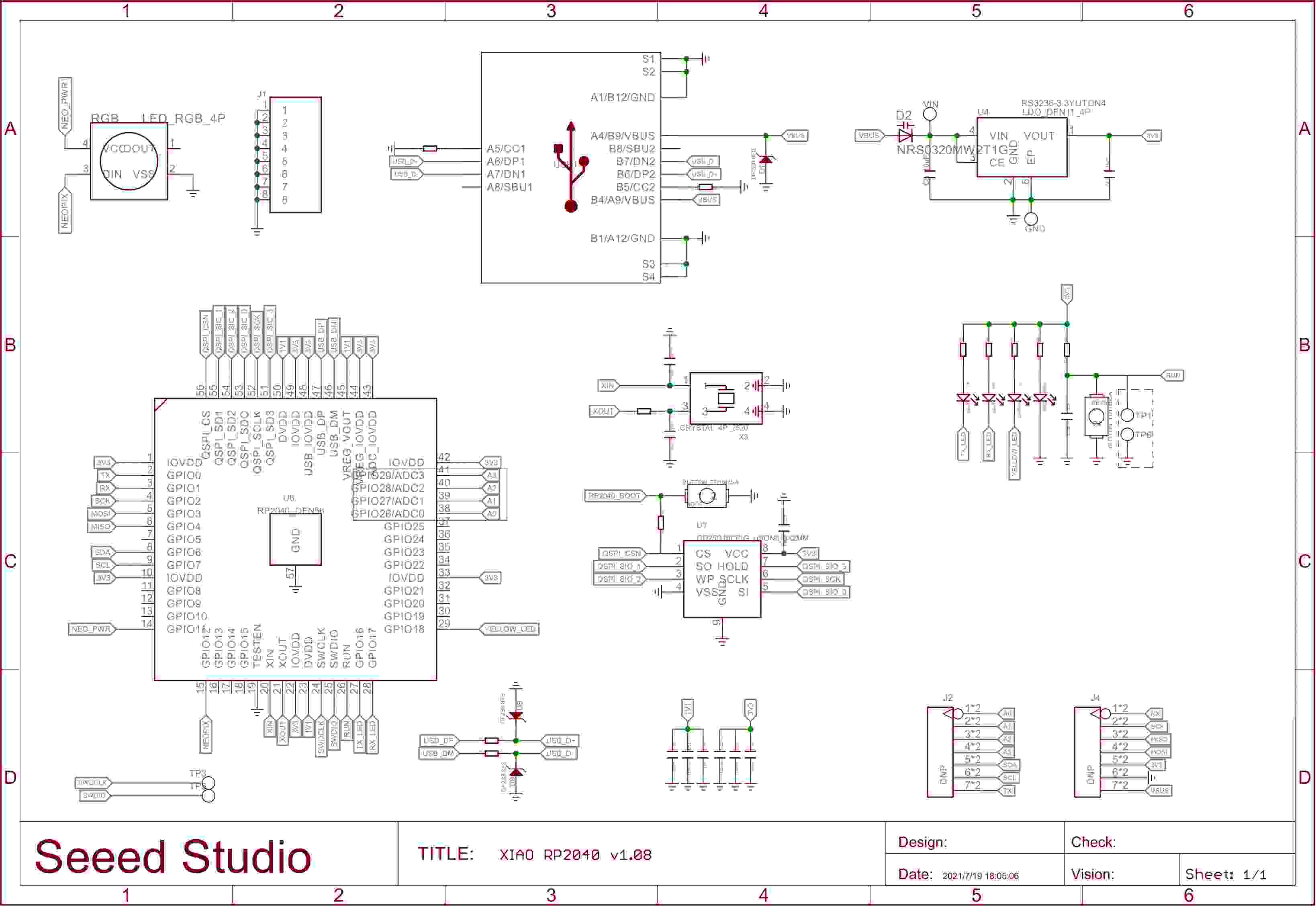
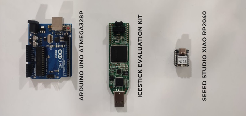
- Group Assignment: Browse through the data sheet for the microcontroller used and compare the performance and development workflows for other architectures
Quentorres Board
In 2024, Adrián Torres significantly redesigned the Quentorres board, originally conceived by Quentin Bolsée. This new version is more versatile and can now program both AVR Series 1 and 2 microcontrollers, as well as ARM microcontrollers. It still has basic input/output features like buttons and LEDs, and it also has breakout pins that make it easy to connect to other components.
.png)
.jpeg)
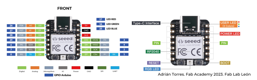
Seeed Studio XIAO RP2040
The Seeed Studio XIAO RP2040 is a tiny but powerful development board perfect for building embedded electronics projects. Its heart is the RP2040, a dual-core processor running at up to 133MHz, providing plenty of muscle for your creations.
The XIAO RP2040 connects to the world around it through various built-in features:
- USB-C: This single port lets you program the board and provide power.
- I/O interfaces: These include digital pins, analog pins, PWM pins, UART, I2C, and SPI, allowing you to connect sensors, actuators, and other components.
- Arduino compatibility: Program the XIAO RP2040 easily using the familiar Arduino IDE and its vast online library and community resources.
Despite its small size, the XIAO RP2040 packs a punch with its processing power, connectivity options, and expandability via additional pins. This makes it ideal for various embedded projects where space is limited.
Programming - Microcontroller Development Board
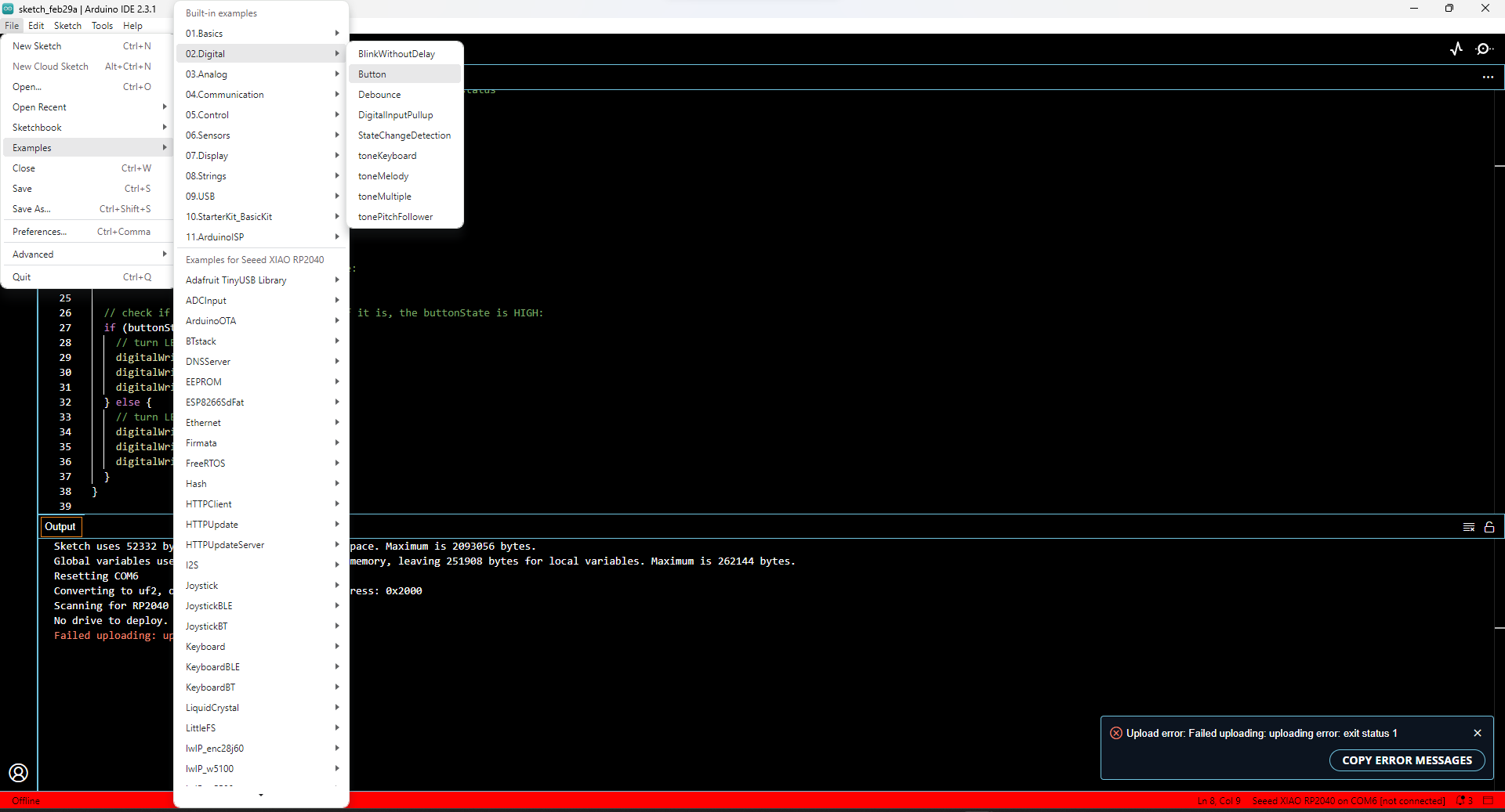
The Arduino IDE (Integrated Development Environment) plays a crucial role in Arduino's popularity. This user-friendly software simplifies both writing code and transferring it to the physical board, making it accessible to beginners and experienced programmers alike.
This week in class, we explored how to assign functions to the buttons on the Quentorres board. Our instructor emphasized the importance of writing algorithms beforehand to understand the logic and streamline the coding process. I found this very helpful!
Using an existing Arduino program as a base, I modified it to fulfill my specific needs. I created two versions of the same program, one using a boolean variable and one without, to control the on/off state of an LED.
Toggling LED with Button (No Boolean Flag)
Algorithm
Step 1: Start
Step 2: Define BUTTON_PIN as pin 27 and LED_PIN as pin 0.
Step 3: Set up LED_PIN as an output and set up BUTTON_PIN as an input.
Step 4: If the button is pressed, turn on led if it's off and turn off it’s on.
Step 5: Repeat step4
.png)
            const int buttonPin = 27;  // the number of the pushbutton pin located from Quentorres Data Sheet
                const int ledPin = 26;    // the number of the LED pin located from Quentorres Data Sheet

                int buttonState = 0;  // variable for reading the pushbutton status
                int LEDState=0; // variable for reading the LED status

                void setup() {
                  // initialize the LED pin as an output:
                  pinMode(ledPin, OUTPUT);
                  // initialize the pushbutton pin as an input:
                  pinMode(buttonPin, INPUT);
                }

                void loop() {
                  // read the state of the pushbutton value:
                  buttonState = digitalRead(buttonPin);
                  if (buttonState==HIGH){
                    // read the state of the LED value:
                    // read the state of the LED value:
                     LEDState = digitalRead(ledPin);
                     if (LEDState==HIGH){
                      digitalWrite(ledPin,LOW);
                     } else {
                      digitalWrite(ledPin,HIGH);
                     }
                  }
                }
Algorithm and Code to Switch ON and OFF an LED using Button (with Boolean)Algorithm
Step 1: Start
Step 2: Define values for button pin and LED pin.
Step 3: Define a boolean operation with variable 'flag' and assign the value 'false'
Step 4: Create a variable for reading the pushbutton status
Step 5: Initialize the button pin as input and LED pin as output
Step 6: Let the variable buttonState read the status of button
Step 7: If buttonState is high, value of 'flag' changes to opposite.
Step 8: Go to Step 6.
.png)
const int buttonPin = 27;  // the number of the pushbutton pin
    const int ledPin_1 = 26;    // the number of the LED pin
    const int ledPin_2 = 0;
    const int ledPin_3 = 1;
    bool flag = false;

    // variables will change:
    int buttonState = 0;  // variable for reading the pushbutton status

    void setup() {
      // initialize the LED pin as an output:
      pinMode(ledPin_1, OUTPUT);
        pinMode(ledPin_2, OUTPUT);
          pinMode(ledPin_3, OUTPUT);
      // initialize the pushbutton pin as an input:
      pinMode(buttonPin, INPUT);
    }

    void loop() {
      // read the state of the pushbutton value:
      buttonState = digitalRead(buttonPin);

      // check if the pushbutton is pressed. If it is, the buttonState is HIGH:
      if (buttonState == HIGH) {
        // turn LED on:
        digitalWrite(ledPin_1, HIGH);
        digitalWrite(ledPin_2, HIGH);
        digitalWrite(ledPin_3, HIGH);
      } else {
        // turn LED off:
        digitalWrite(ledPin_1, LOW);
        digitalWrite(ledPin_2, LOW);
        digitalWrite(ledPin_3, LOW);
      }
    }
While testing the code, we encountered an issue where the LED flickered rapidly when the button was pressed repeatedly. This phenomenon, explained by our instructor, is due to "switch bounce" - a brief, temporary fluctuation in the button's electrical signal when pressed. This can lead to multiple readings being interpreted as separate presses, causing the LED to blink.
Bouncing and Debouncing
The term "button bounce" describes the occurrence observed when a mechanical button or switch undergoes pressing or releasing actions. Upon pressing or releasing, the internal metal contacts of the button engage in momentary yet swift electrical connections and disconnections. This series of actions leads to multiple rapid transitions in the electrical signal, rather than a single smooth transition. These swift transitions, referred to as "bounces," have the potential to induce unreliable or erratic responses in electronic circuits designed to react to button presses.
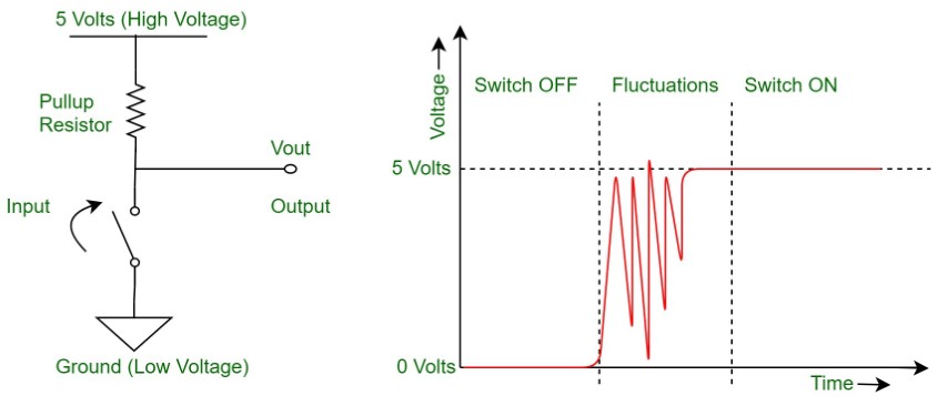
In the video footage, it's evident that pressing the button doesn't consistently change the LED's state as desired. There are instances where the LED remains unchanged, attributable to the bouncing effect. Moreover, prolonged button presses induce flickering in the LED. To address this issue, a debounce delay is necessary. Button debouncing is a vital technique in electronics, aimed at ensuring dependable detection of button presses. By mitigating erratic transitions, debouncing facilitates the provision of a steady and precise signal.
So I have modified the code
const int buttonPin = 27;  // the number of the pushbutton pin
    const int ledPin = 26;    // the number of the LED pin

    const int buttonPin = 27;  // the number of the pushbutton pin
    const int ledPin = 26;    // the number of the LED pin
    bool flag=false; // boolean operation
    bool pressed=false;
    // variables will change:
    int buttonState = 0;  // variable for reading the pushbutton status

    void setup() {
      // initialize the LED pin as an output:
      pinMode(ledPin, OUTPUT);
      // initialize the pushbutton pin as an input:
      pinMode(buttonPin, INPUT);
      delay(2000);
    }

    void loop() {
      // read the state of the pushbutton value:
      buttonState = digitalRead(buttonPin);
    if (buttonState==HIGH){
      if (pressed==false){
          flag=!flag; //changes to opposite value
          pressed=true;
      }

    }else{
      pressed=false;
      delay(50);
    }
    digitalWrite(ledPin, flag);

    }
Serial Communication
Serial communication involves the transmission of data bit by bit, sequentially, along a communication channel or computer bus. This method stands apart from parallel communication, where multiple bits are sent simultaneously. Commonly utilized for exchanging data between a microcontroller and peripherals or other computing devices, serial communication facilitates efficient data transmission.
Within the Arduino IDE, the Serial Monitor serves as a crucial feature enabling bidirectional data exchange between a board and a computer via the USB connection. This tool proves invaluable for debugging and project interaction, fostering real-time communication between the computer and the board.
The baud rate, within the Arduino IDE context, denotes the speed of communication over the Serial connection, measured in bits per second (bps). Proper communication necessitates matching baud rates between the board and the connected device to ensure mutual comprehension during data exchange.
const int buttonPin = 27;  // the number of the pushbutton pin
    const int ledpin_1 = 26;   // the number of the LED pin
    // variables will change:
    int buttonState = 0;  // variable for reading the pushbutton status
    bool pressed;
    void setup() {
    Serial.begin(9600);
      pinMode(ledpin_1, OUTPUT);


      pinMode(buttonPin, INPUT);
      Serial.println("this is an LED example Board for FAB24");

    }

    void loop() {

      buttonState = digitalRead(buttonPin);


      if (buttonState == HIGH)
      {

        if (pressed == false)
        {
      Serial.println("button is pressed");
          pressed = true;

          if (digitalRead(ledpin_1) == LOW)
          {
            Serial.println("LED is ON");
            digitalWrite(ledpin_1, HIGH);

          } else {Serial.println("LED is OFF");
            digitalWrite(ledpin_1, LOW);

          }
        }
      }
     else {
        pressed = false;
        delay(50);
      }
    }
Below is the revised code I've crafted to acquire data on LED activation/deactivation states and Button Press events, operating at a baud rate of 9600.
Recursive Function
A recursive function is like a loop that repeats inside a function. It calls itself until it reaches a stopping point, preventing endless repetition.
Here's a code I tweaked with ChatGPT 3.5 to toggle LEDs one by one with each button press using recursion.
I then asked ChatGPT to adjust the code to toggle three LEDs in sequence with each button press, still using recursion.
const int buttonPin = 27;   // the number of the pushbutton pin
    const int ledPins[] = {26, 0, 1};  // Pins for LEDs
    int buttonState = 0;         // variable for reading the pushbutton status
    bool pressed;

    void setup() {
      Serial.begin(9600);

      // Initialize LEDs as outputs
      for (int i = 0; i < sizeof(ledPins) / sizeof(ledPins[0]); i++) {
        pinMode(ledPins[i], OUTPUT);
      }

      pinMode(buttonPin, INPUT);
      Serial.println("This is an LED example Board for FAB24");
    }

    // Function to turn on LEDs one by one
    void lightUp(int index) {
      if (index < sizeof(ledPins) / sizeof(ledPins[0])) {
        digitalWrite(ledPins[index], HIGH);
        delay(500); // Adjust delay as needed
        lightUp(index + 1);
      }
    }

    // Function to turn off LEDs in reverse order
    void turnOff(int index) {
      if (index >= 0) {
        digitalWrite(ledPins[index], LOW);
        delay(500); // Adjust delay as needed
        turnOff(index - 1);
      }
    }

    void regressiveLED() {
      lightUp(0);  // Turn on LEDs one by one
      turnOff(sizeof(ledPins) / sizeof(ledPins[0]) - 1); // Turn off LEDs in reverse order
    }

    void loop() {
      buttonState = digitalRead(buttonPin);

      if (buttonState == HIGH) {
        if (pressed == false) {
          Serial.println("Button is pressed");
          pressed = true;

          // Toggle the state of LED 1
          if (digitalRead(ledPins[0]) == LOW) {
            Serial.println("LED is ON");
            digitalWrite(ledPins[0], HIGH);
            regressiveLED(); // Call the function to control LEDs
          } else {
            Serial.println("LED is OFF");
            digitalWrite(ledPins[0], LOW);
            // No need to call regressiveLED() when turning off the LED
          }
        }
      } else {
        pressed = false;
        delay(50);
      }
    }
MicroPython
MicroPython stands out as a tailored Python variant designed specifically for embedded systems. It differs from standard CPython by focusing on microcontrollers and devices with limited resources. By incorporating partial native code compilation, it enhances performance and minimizes resource consumption. Although it supports only a subset of Python 3.5 features, MicroPython shines in tasks that demand precise hardware management and sensor interfacing, making it a preferred choice for IoT projects. While MicroPython caters well to embedded development needs, it's essential to weigh its advantages against the constraints it poses compared to CPython. Thorough comparisons between MicroPython and alternative implementations shed light on their disparities and suitability across diverse application scenarios.
I referred this documentation and followed the same steps.
First, I downloaded and installed Thonny Editor.
Thonny is an Integrated Development Environment (IDE) designed especially for beginners learning Python programming. Its simplicity and straightforward interface make it an excellent choice for those new to programming, as well as for more experienced developers seeking a lightweight tool.
.png)
.png)
    from machine import Pin, Timer
        led = Pin(25, Pin.OUT)
        Counter = 0
        Fun_Num = 0

        def fun(tim):
            global Counter
            Counter = Counter + 1
            print(Counter)
            led.value(Counter%2)

        tim = Timer(-1)
        tim.init(period=1000, mode=Timer.PERIODIC, callback=fun)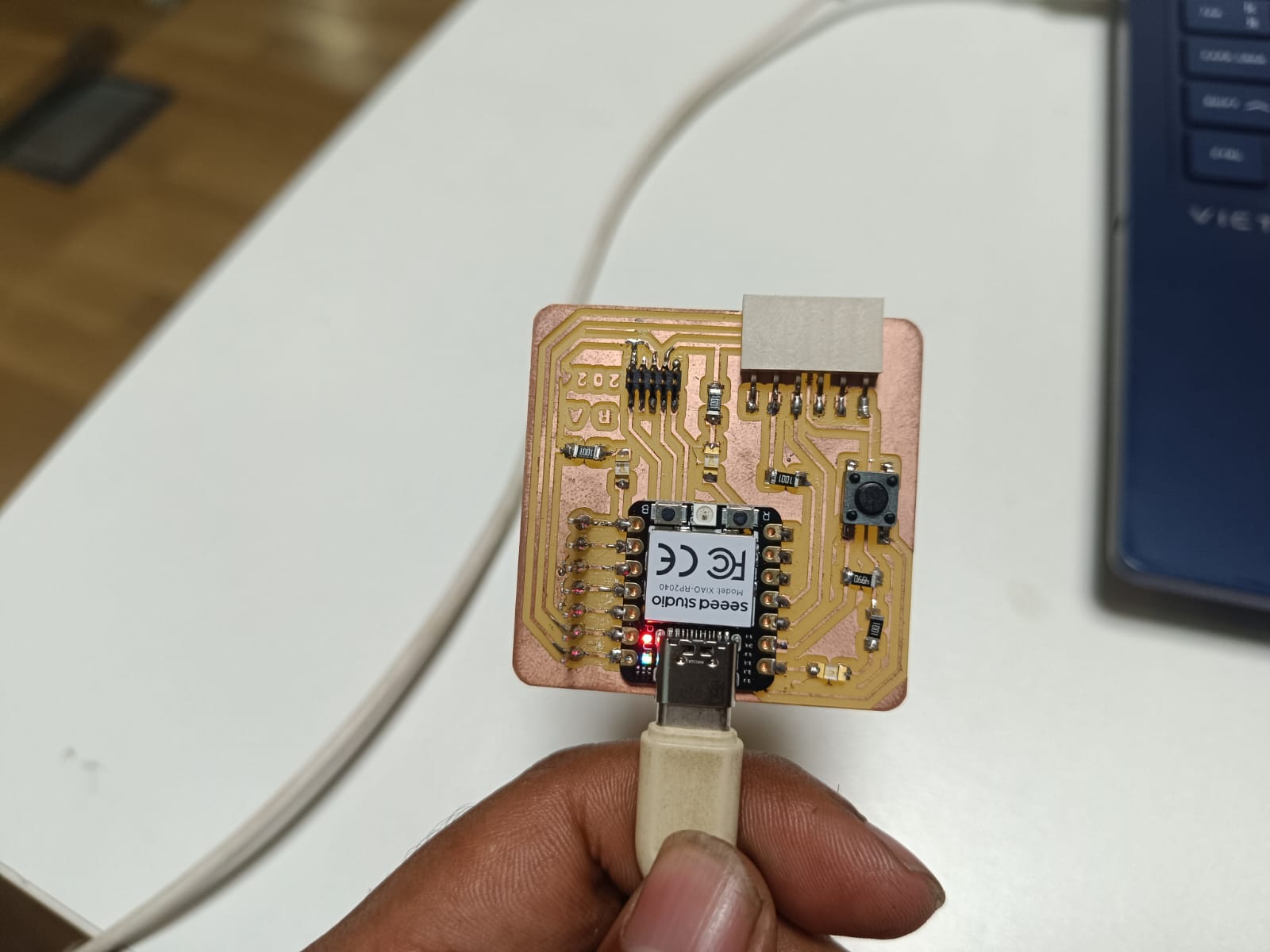
Following the tutorial, the subsequent piece of code demonstrated how to illuminate the RGB LED on the Seeed Studio XIAO RP2040. I proceeded by downloading the "ws2812.py" library and storing it within the Thonny environment for future use.
  from ws2812 import WS2812
        import utime
        import machine
        power = machine.Pin(11,machine.Pin.OUT)
        power.value(1)
        BLACK = (0, 0, 0)
        RED = (255, 0, 0)
        YELLOW = (255, 150, 0)
        GREEN = (0, 255, 0)
        CYAN = (0, 255, 255)
        BLUE = (0, 0, 255)
        PURPLE = (180, 0, 255)
        WHITE = (255, 255, 255)
        COLORS = (BLACK, RED, YELLOW, GREEN, CYAN, BLUE, PURPLE, WHITE)

        led = WS2812(12,1)#WS2812(pin_num,led_count)

        while True:
            print("Beautiful color")
            for color in COLORS:
                led.pixels_fill(color)
                led.pixels_show()
                utime.sleep(0.2)
HC-SR04 Ultrasonic Sensor: A Popular Choice for Measuring Distance
The HC-SR04 ultrasonic sensor is a widely used and affordable sensor for measuring the distance between an object and the sensor. It operates on the principle of ultrasonics, which involves sending and receiving sound waves at frequencies above the human hearing range.
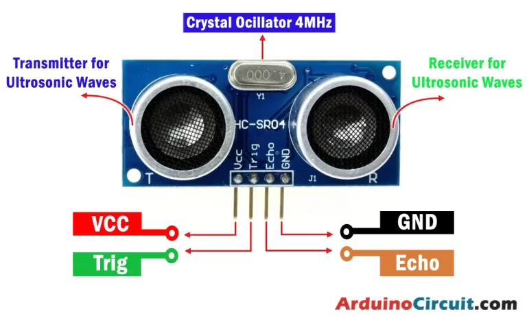
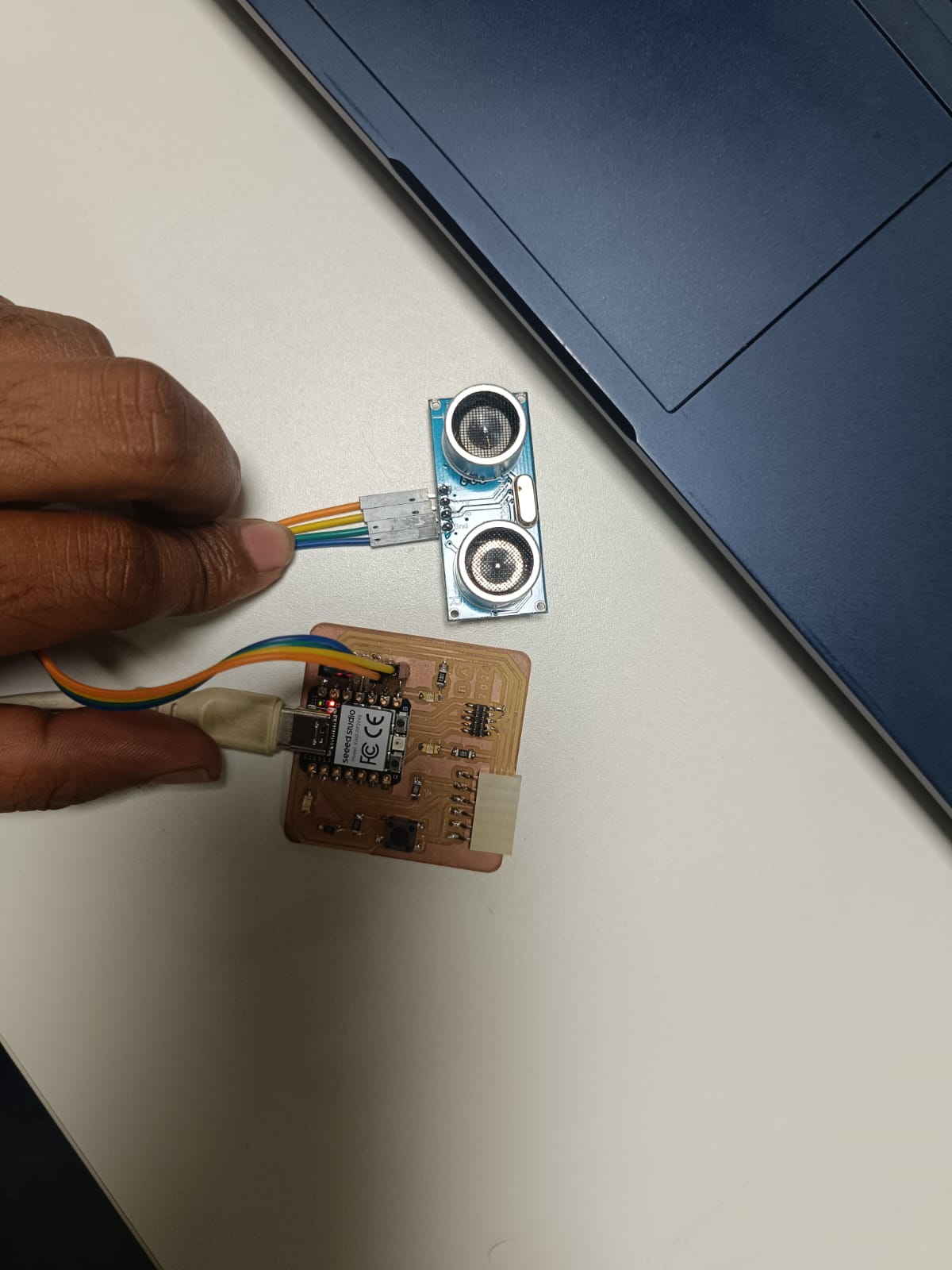
Connect the trigger pin,echo pin,ground (GND) pin,VCC pin of the ultrasonic sensor to digital pin on the Seeed Xiao RP2040.
Next I wrote the code using ChatGPT
const int triggerPin = 4p; // GPIO pin for the ultrasonic sensor trigger
        const int echoPin = 3;    // GPIO pin for the ultrasonic sensor echo

        void setup() {
          Serial.begin(9600);
          pinMode(triggerPin, OUTPUT);
          pinMode(echoPin, INPUT);
        }

        void loop() {
          // Trigger ultrasonic sensor by sending a pulse
          digitalWrite(triggerPin, LOW);
          delayMicroseconds(2);
          digitalWrite(triggerPin, HIGH);
          delayMicroseconds(10);
          digitalWrite(triggerPin, LOW);

          // Measure the duration of the echo pulse
          unsigned long duration = pulseIn(echoPin, HIGH);

          // Calculate the distance in centimeters
          float distance = (duration * 0.0343) / 2;

          // Print the distance to the Serial Monitor
          Serial.print("Distance: ");
          Serial.print(distance);
          Serial.println(" cm");

          delay(1000); // Wait for a short duration before the next measurement
        }
Results
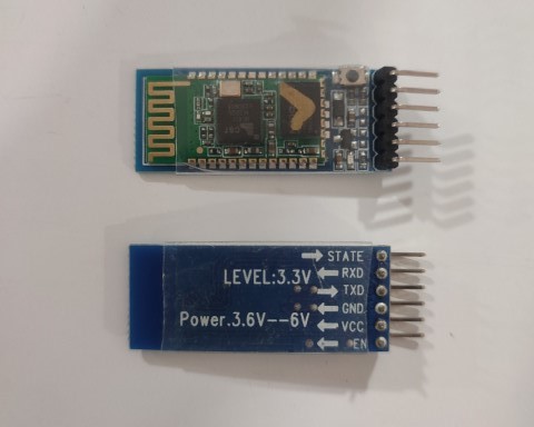
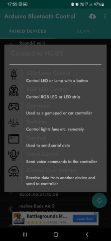
HC-05 Bluetooth Module
The HC-05 is a widely used Bluetooth module that enables wireless communication between devices. It's commonly employed in various electronics projects, including those with Arduino and other microcontroller platforms. The HC-05 can function as both a Bluetooth master and slave device, which allows it to both initiate and accept connections.
Arduino Bluetooth Controller app, a versatile and intuitive mobile tool engineered to streamline wireless communication and management between an Arduino board and a smartphone or tablet using Bluetooth technology. Acting as a conduit, this app facilitates the seamless exchange of data between the circuit and your device, empowering users to remotely oversee an array of projects and gadgets.
        #include < SoftwareSerial.h >

        const int ledPin = 0; // GPIO pin for the LED
        SoftwareSerial bluetoothSerial(3, 4); // RX, TX pins for HC-05

        void setup() {
            Serial.begin(9600);          // Initialize the serial communication for debugging
            bluetoothSerial.begin(9600); // Initialize Bluetooth serial communication
            pinMode(ledPin, OUTPUT);      // Set the LED pin as an output
        }

        void loop() {
            if (bluetoothSerial.available() > 0) {
            char command = bluetoothSerial.read();

            // Toggle LED based on received command
            if (command == '1') {
                digitalWrite(ledPin, HIGH); // Turn on LED
                Serial.println("LED ON");
            } else if (command == '0') {
                digitalWrite(ledPin, LOW);  // Turn off LED
                Serial.println("LED OFF");
            }
          }
        }
Group Assignment
This week, our group project was to dig into the Quentorres board's datasheet and see how it compares to other architectures in terms of performance and how you develop for them.
For further details, click on the link- Group Assignment-Week 6